Transform Menu
Apply advanced geometric transformations such as surface projection, normal flipping, and path offsetting to align tool paths with 3D part geometry.
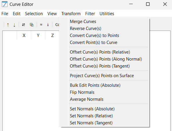
This menu contains geometric logic that fundamentally alters how the robot relates to the workpiece. The tools that do such transformations include:
1.Merge Curves: Takes multiple separate curve segments and stitches them into a single continuous path. This is vital for CNC-style operations where you want the robot to maintain a constant feed rate across multiple CAD layers.
2.Reverse Curve(s): Flips the point list from end-to-start. This is the fastest way to correct a path where the robot is moving "backward" relative to the desired machining direction.
3.Convert Curve(s) to Points: Breaks the "chain" of a curve, turning it into a list of standalone targets. This is useful if you want to perform Pick-and-Place operations at specific nodes of a path rather than following the line.
4.Convert Point(s) to Curve: The inverse of the above; it takes individual points and draws a robotic path between them. Use this after importing a list of random measurement points to turn them into a traversable path.
5.Offset Curve(s) Points (Relative): Applies a fixed relative translation to the curve points based on the combination of selected axes. For example, adding 50mm to the X and Y axes moves the entire path diagonally.
6.Offset Curve(s) Points (Along Normal): A complex translation that moves points away from or into the part surface based on their individual orientation.
7.Offset Curve(s) Points (Tangent): Shifts points along the direction of travel. This is often used to "lead-in" or "lead-out" of a cut, extending the path slightly forward or backward without deviating from the line.
8.Project Curve(s) Points on Surface: Casts your 2D or 3D points onto the mesh of a selected object. This ensures that even if your CAD path is slightly off, the robot will physically touch the surface of the part in the simulation.
9.Bulk Edit Points (Absolute): An "override" tool that allows you to force a specific absolute value (with respect to the parent reference frame). For example, you can set the X values of all points to 100.0. This is dangerous but powerful for aligning a messy path to a specific plane.
10.Flip Normals: Rotates the tool orientation (IJK) by 180 deg.
11.Average Normals: Compares the orientation of neighboring points and smooths out sharp angular changes. This prevents the robot wrist from "flipping" or jerking during complex curved motions.
12.Set Normals (Absolute): Forces all selected points to point in a single direction (e.g., [0, 0, 1]). This is perfect for simple 3-axis flat-bed operations where tool orientation never changes.
13.Set Normals (Relative): Applies a rotation (e.g., +15 deg around Y) to the existing normals. This allows you to "tilt" a toolpath to provide better clearance for a bulky robot spindle.
14.Set Normals (Tangent): Calculates the normal vector based on the direction of travel. This is used for "knife cutting" applications where the blade must always face forward along the path.