Curve Utilities
The Curve Utilities Add-in for RoboDK allows you to manipulate curves in a user-friendly manner. You can manipulate single points (their position values and normals), filter curves and more. It is a powerful, integrated toolkit designed to transform raw geometric data into high-precision robotic tool paths within RoboDK.
The Curve Utilities Add-in provides a dedicated interface for point-cloud manipulation, the utility enables users to perform complex geometric operations such as projecting 2D sketches onto 3D curved surfaces, mathematically smoothing noisy paths using different algorithms, and improving cycle times by providing an option to re-order multiple curve segments for the most efficient robot travel. Furthermore, it offers advanced cleaning filters to remove redundant points and correct tool orientation (normals), ensuring that the robot maintains perfect perpendicularity to a workpiece during tasks like laser cutting, dispensing, or deburring.
Installation
You can find the RoboDK Curve Utilities Add-In in the Add-ins section of the library.
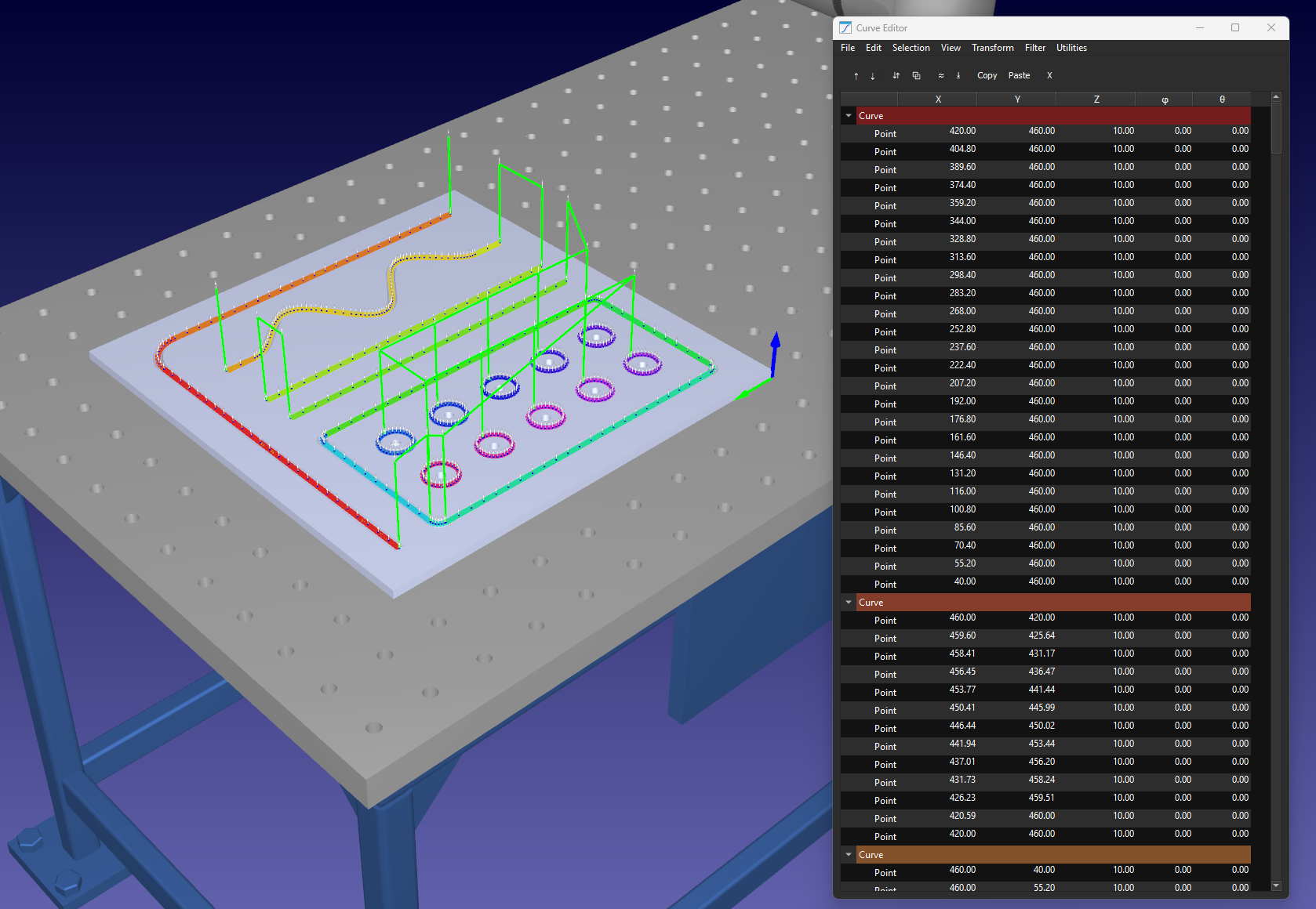
Menu Bar
The Curve Utilities Add-In’s Menu Bar consists of a main window which includes the commands required to load/save curves, filter curves, transform them and more.
1.Select Utilities.
2.Select Curve Utilities
3.Select Curve Editor (or the corresponding toolbar action).
File Menu
Manage your robotic project data by importing and exporting CAD paths, CSV coordinate files, and SVG vectors for hassle-free path loading.
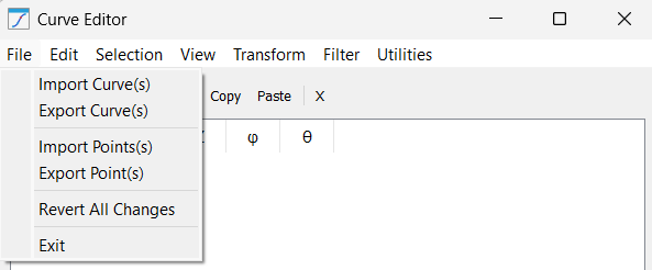
This menu manages the lifecycle of your curve/point data with the help of the following tools:
1.Import Curve(s): This tool allows you to bring in complex tool paths from various formats, including CSV, SVG, and DXF. When importing, the system automatically attempts to parse the structure and generate distinct curve items in the editor tree based on the file’s internal layers or groups.
2.Export Curve(s): Use this to save your refined work. It extracts all current geometric data, including coordinates and normal vectors, into a standardized CSV or TXT file. This is vital for version control or for transferring paths between different RoboDK stations.
3.Import Point(s): Unlike importing entire curves, this function allows you to inject standalone points into an existing selection. It is primarily used for manually "patching" holes in a tool path or adding specific approach/retract points that were not present in the original CAD file. Another application with points is where you have a drilling project and the position of holes to be drilled are represented by coordinate points.
4.Export Point(s): This provides a raw data dump of specific selected coordinates. It is highly useful when you need to extract specific target values for documentation, external spreadsheet analysis, or for use in high-level script programming.
5.Revert All Changes: A safety feature that acts as a global "undo". It reloads the curve data as it existed at the start of the session, discarding all filters, offsets, and transformations performed in the editor since the last save or import.
6.Exit: Safely terminates the Curve Utilities session and returns to the main 3D simulation environment.
Edit Menu
Perform standard point cloud editing tasks such as cutting, copying, pasting, and deleting individual coordinate rows within your robotic path.
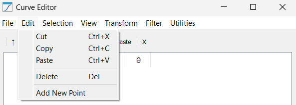
This menu offers common table manipulation tools for handling high-density coordinate data:
1.Cut: Removes the selected points or curves from the list while storing them in the clipboard. This is often used to "re-parent" a segment from one path to another within the same project.
2.Copy: Duplicates the highlighted geometric data to the clipboard. This is useful for replicating patterns (like a bolt hole circle) across multiple locations on a part without re-importing the source file.
3.Paste: Inserts the clipboard data at the current cursor position. If a curve is selected, the points are appended at the end; if a specific row is selected, the points are injected directly below.
4.Delete: Permanently clears the selected data from the editor. This is essential for manual cleaning of "stray" points that often appear at the beginning or end of low-quality CAD exports.
5.Add New Point: Manually creates a new point row with coordinates (0, 0, 0). This allows the user to insert specific coordinates when a precise physical measurement is known but not represented in the 3D model.
Selection Menu
Quickly organize your workflow by highlighting specific curves or points and re-ordering them to define the robot's execution sequence.
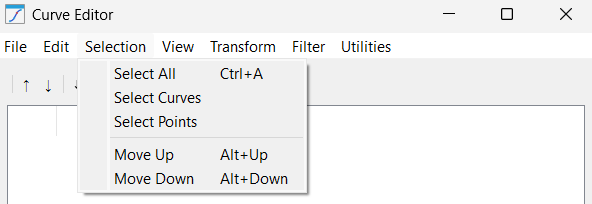
These functions allow for easy control over data selection, which is critical before applying filters or transformations:
1.Select All: Highlights every single point and curve object currently loaded in the session. Use this when you need to apply a global transformation, such as an XYZ offset, to the entire project.
2.Select Curves: A filter that selects only the "Curve" containers in the tree. This is helpful when you want to move or sort the path segments as complete units rather than individual points.
3.Select Points: A filter that selects only the "Point" rows within the table. This is standard for applying smoothing or resampling algorithms that only operate on coordinate lists.
4.Move Up: Shifts the selected item one position higher in the list. This directly changes the robot’s execution order, forcing it to visit that specific point or segment earlier in the program sequence.
5.Move Down: Shifts the selected item one position lower. This is typically used to move retract points to the very end of a curve to ensure the robot clears the part safely.
View Menu
Adjust your workspace by toggling IJK orientation columns, expanding data trees, and calculating point-to-point distances for better path visualization.
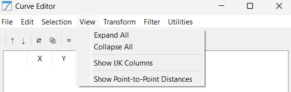
This menu provides tools to manage the visual density of the data table and tree as listed below:
1.Expand All: Fully opens the tree structure to show every point inside every curve. While useful for deep inspection, it can result in a very long list when working with high-resolution paths.
2.Collapse All: Tucks all points back into their parent curve folders. This is the preferred view for organizational tasks like sorting or merging, as it prevents the UI from becoming cluttered.
3.Show IJK Columns: Toggles the visibility of the orientation vectors. If your application is a simple 3-axis task (like a flat waterjet cut), you can hide these to simplify the interface.
4.Show Point-to-Point Distances: Calculates and displays the millimeter gap between each point. This is an invaluable diagnostic tool for finding gaps in a path that might cause a robot to "jump" or trigger a speed error.
Transform Menu
Apply advanced geometric transformations such as surface projection, normal flipping, and path offsetting to align tool paths with 3D part geometry.
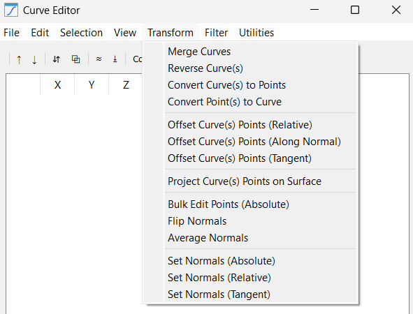
This menu contains geometric logic that fundamentally alters how the robot relates to the workpiece. The tools that do such transformations include:
1.Merge Curves: Takes multiple separate curve segments and stitches them into a single continuous path. This is vital for CNC-style operations where you want the robot to maintain a constant feed rate across multiple CAD layers.
2.Reverse Curve(s): Flips the point list from end-to-start. This is the fastest way to correct a path where the robot is moving "backward" relative to the desired machining direction.
3.Convert Curve(s) to Points: Breaks the "chain" of a curve, turning it into a list of standalone targets. This is useful if you want to perform Pick-and-Place operations at specific nodes of a path rather than following the line.
4.Convert Point(s) to Curve: The inverse of the above; it takes individual points and draws a robotic path between them. Use this after importing a list of random measurement points to turn them into a traversable path.
5.Offset Curve(s) Points (Relative): Applies a fixed relative translation to the curve points based on the combination of selected axes. For example, adding 50mm to the X and Y axes moves the entire path diagonally.
6.Offset Curve(s) Points (Along Normal): A complex translation that moves points away from or into the part surface based on their individual orientation.
7.Offset Curve(s) Points (Tangent): Shifts points along the direction of travel. This is often used to "lead-in" or "lead-out" of a cut, extending the path slightly forward or backward without deviating from the line.
8.Project Curve(s) Points on Surface: Casts your 2D or 3D points onto the mesh of a selected object. This ensures that even if your CAD path is slightly off, the robot will physically touch the surface of the part in the simulation.
9.Bulk Edit Points (Absolute): An "override" tool that allows you to force a specific absolute value (with respect to the parent reference frame). For example, you can set the X values of all points to 100.0. This is dangerous but powerful for aligning a messy path to a specific plane.
10.Flip Normals: Rotates the tool orientation (IJK) by 180 deg.
11.Average Normals: Compares the orientation of neighboring points and smooths out sharp angular changes. This prevents the robot wrist from "flipping" or jerking during complex curved motions.
12.Set Normals (Absolute): Forces all selected points to point in a single direction (e.g., [0, 0, 1]). This is perfect for simple 3-axis flat-bed operations where tool orientation never changes.
13.Set Normals (Relative): Applies a rotation (e.g., +15 deg around Y) to the existing normals. This allows you to "tilt" a toolpath to provide better clearance for a bulky robot spindle.
14.Set Normals (Tangent): Calculates the normal vector based on the direction of travel. This is used for "knife cutting" applications where the blade must always face forward along the path.
Filter Menu
Enhance motion quality using path smoothing algorithms, duplicate point removal, and line simplification to ensure fluid, vibration-free robot travel.
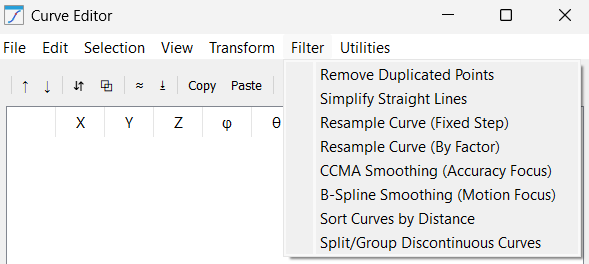
This menu comprises of advanced mathematical algorithms used to improve the path for industrial-grade motion in the form of following features:
1.Remove Duplicated Points: Deletes consecutive points that are effectively identical.
2.Simplify Straight Lines: Analyzes segments and removes redundant points that lie on a perfectly straight line. It reduces a path with 1,000 points to 2 points (start/end) if the segment is straight, drastically reducing program size.
3.Resample Curve (Fixed Step): Adds new points at the fixed step intervals to force a specific distance between all points (e.g., exactly 5.0mm). This is critical for dispensing glue or sealant, where a constant speed/distance relationship is required for a uniform bead.
4.Resample Curve (By Factor): Increases the number of segments by a multiplier (e.g., 2 as an input will break each segment of the curve into 2 parts; it will add an extra point between every consecutive points).
5.CCMA Smoothing (Accuracy Focus): Uses a Moving Average to dampen "jitter" in the path. Because it averages nearby points, it is excellent for 3D scan data where you want to remove noise while staying very close to the original coordinates.
6.B-Spline Smoothing (Motion Focus): Creates a high-order polynomial spline through the points.
7.Sort Curves by Distance: It re-orders curve segments so the robot always moves to the closest next path start, minimizing the time spent moving through the air.
8.Split/Group Discontinuous Curves: Scans for large physical gaps in a path and automatically splits them into separate RoboDK items. This allows you to treat "Island" paths (like letters in a logo) as separate operations.
Utilities Menu
Finalize your automation setup by converting curves to robot targets and importing external DXF or program files for simulation.
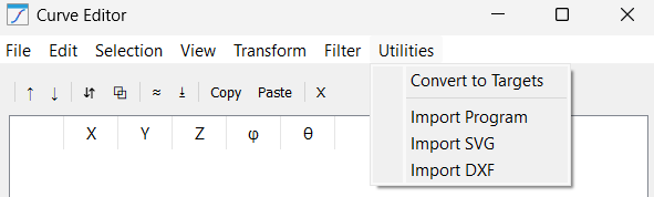
This menu holds integration tools to move your work from the editor to the robot:
1.Convert to Targets: The final step. It takes your refined mathematical data and generates physical "Targets" in the RoboDK tree, ready for a "Curve Follow Project" or "Robot Program".
2.Import Program: An advanced reverse-engineering tool. It extracts the coordinate data from an existing robot program (like a script or .src file) and brings it into the editor so you can smooth or filter a legacy path.
3.Import SVG: Dedicated vector art importer. It translates the Bezier curves of a logo or text into a robotic path, making it the primary tool for laser engraving or decorative painting tasks.
4.Import DXF: The standard engineering interface. It pulls in lines, arcs, and polylines from CAD drawings, maintaining the exact scale and dimensions intended by the designer.
Action Buttons
The Curve Utilities Add-In includes a few shortcut buttons just below the menu bar to make commonly used features easily accessible.
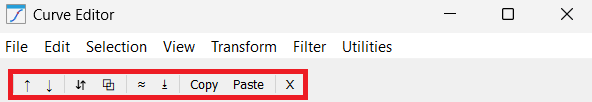
These action buttons include:
1.Move Up
2.Move Down
3.Reverse Curve
4.Merge Curves
5.Remove Duplicates
6.Project on Surface
7.Copy
8.Paste
9.Delete