Additional Options and Settings
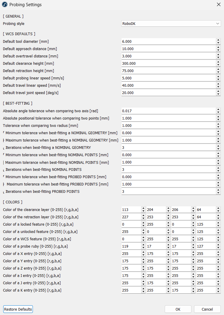
RoboDK provides a global Probing Settings window. Select Probing ➔ Settings to open it. The values you set here are the defaults used whenever you start a new probing project; they do not change projects that already exist. Click Restore Defaults to go back to the standard values.
General
Probing style selects how probing routines are written. RoboDK is the default and generates search instructions executed through a robot driver. The six Renishaw entries (for ABB, Fanuc, KUKA, Yaskawa, Mitsubishi and Staubli) generate Renishaw Daytona macro calls for the matching controller.

WCS Defaults
Instead of editing distances and other parameters manually every time you build a project, these values automatically pre-populate your project settings:
1.Default tool diameter [mm]: the ruby diameter at the probe tip. Default: 6 mm.
2.Default approach distance [mm]: the distance at which the probe slows down in front of a surface. Default: 10 mm.
3.Default overtravel distance [mm]: the extra search depth past the expected surface. Default: 3 mm.
4.Default clearance height [mm]: the safe height used before the first point and after the last point. Default: 300 mm.
5.Default retraction height [mm]: the height the probe backs off to between points. Default: 75 mm.
6.Default probing linear speed [mm/s]: the touch-sensing search speed. Default: 5 mm/s.
7.Default travel linear speed [mm/s]: the linear speed in free air. Default: 40 mm/s.
8.Default travel joint speed [deg/s]: the joint speed for travel moves. Default: 20 deg/s.
Best-Fitting
These parameters control how RoboDK mathematically aligns measured points to nominal CAD geometry:
1.Absolute angle tolerance when comparing two axes [rad]: The maximum angular deviation allowed when matching feature axes.
2.Absolute positional tolerance when comparing two points [mm]: The maximum positional error allowed between probed and nominal points.
3.Tolerance when comparing two radius [mm]: The maximum allowed difference when matching measured hole or sphere radii to CAD models.
4.Best-Fitting Tolerances and Iterations: These define the minimum tolerance, maximum tolerance, and iteration limit when best-fitting Nominal Geometry, Nominal Points, and Probed Points.
Colors
1.Clearance and Retraction Layers: You can adjust the transparency and color of the safe movement planes.
2.Feature States: You can also customize colors for locked, unlocked, and WCS features.
3.Probe Ruby: You can change the color of the probe stylus tip.
4.Coordinate and Vector Indicators: You can assign distinct colors for X, Y, Z positions and I, J, K approach vector fields which are visible in the settings table.


