Creating a Probing Project
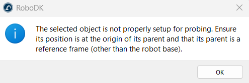
Set up your RoboDK station with the robot, the probe tool and the part you want to measure. The part must belong to a dedicated reference frame: place the object directly under that frame, leave it at the exact origin of the frame, and make sure the frame is not the robot base. Calibration works by moving that reference frame, so the part itself must not carry a pose of its own.
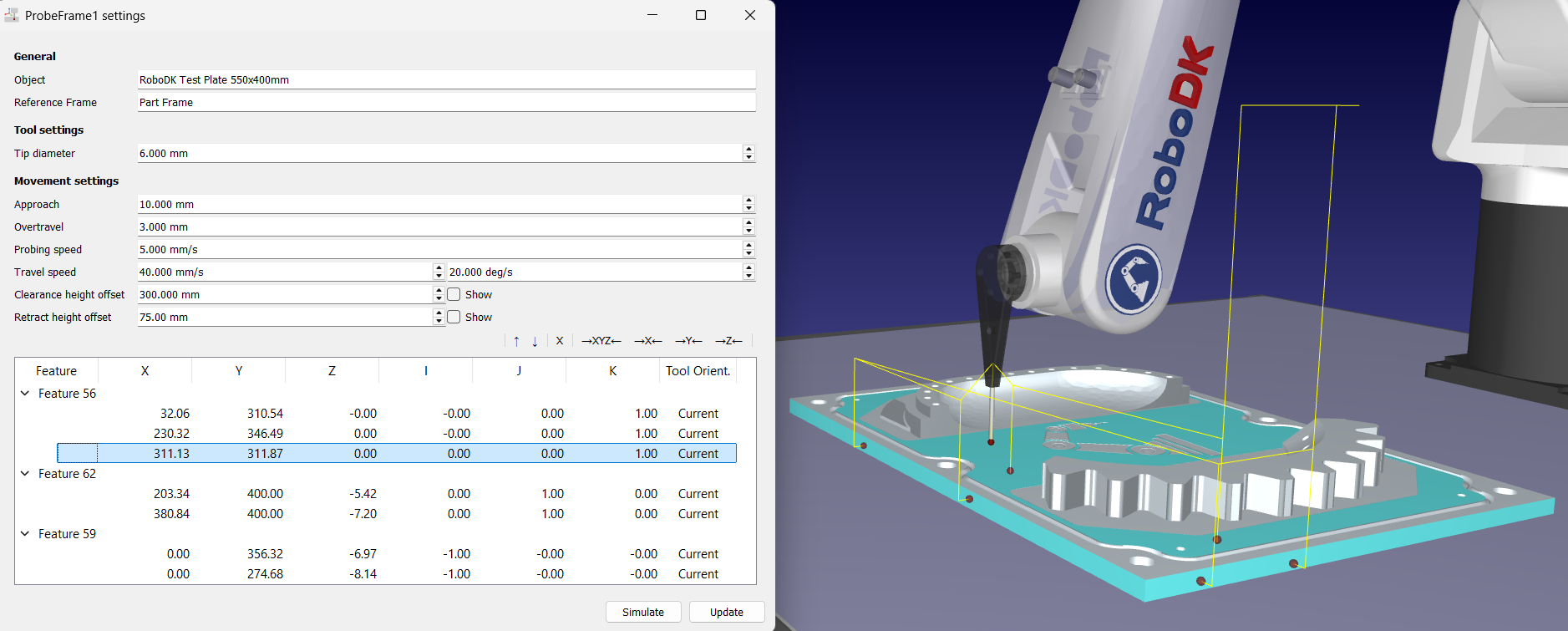
Select Probing ➔ Probe Reference Frame Project in the menu bar, or click the matching button in the toolbar. RoboDK adds a ProbeFrame1 settings item to the station tree and opens its editor window.
The editor groups the probing sequence settings in three sections:
1.General shows the Object being probed and its Reference Frame. Both fields are read-only; they are filled in automatically when you click the part to add your first probing point.
2.Tool settings holds Tip diameter, the diameter of the ruby at the tip of your stylus (6 mm by default). Enter the exact value: RoboDK offsets every surface point by half of it along the surface normal to obtain the tool contact point, so a wrong diameter shifts every measurement.
3.Movement settings holds the distances, speeds and heights used around each point:
a.Approach (10 mm by default, 2 to 100 mm) is the distance in front of the surface where the probe switches from travel speed to probing speed.
b.Overtravel (3 mm by default, 0 to 100 mm) is how far past the expected contact point the probe keeps searching, so contact is still made when the real part sits slightly away from its nominal position.
c.Probing speed (5 mm/s by default) is the slow linear speed used while searching for contact. Keep it low to protect the probe and improve repeatability.
d.Travel speed (40 mm/s and 20 deg/s by default) is used for the moves in free air between points.
e.Clearance height offset (300 mm by default) is the height the robot travels at before the first point and after the last point of the whole sequence.
f.Retract height offset (75 mm by default) is the height the probe backs off to between two points, within a feature as well as between features.
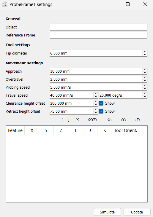
Click your object, such as a part or a fixture, to create a first probing point. Doing so fills in the two read-only General fields of the ProbeFrame1 settings window:
1.Object
2.Reference Frame