Final Run
Now that all the points are defined, the remaining steps are to simulate the sequence, generate the robot program and calibrate the reference frame.
Enable Simulated Probing
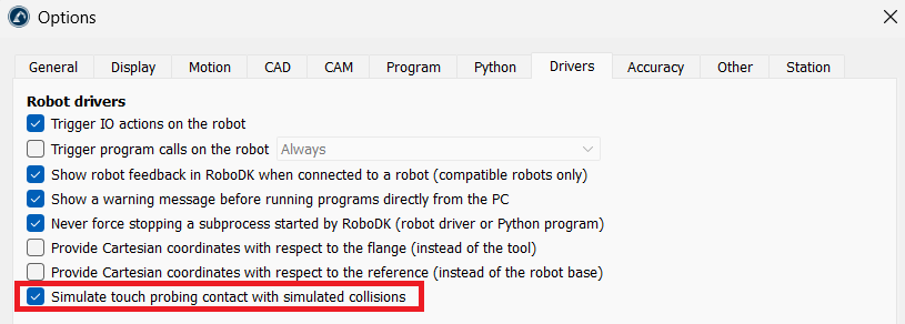
To test the routine without a real probe, let RoboDK simulate the trigger. Select Tools ➔ Options ➔ Drivers, select Simulate touch probing contact with simulated collisions and click OK. The search moves then stop on the simulated contact between the probe and the part; the Add-in enables that collision pair for you when it generates the program.
Preview the Simulation
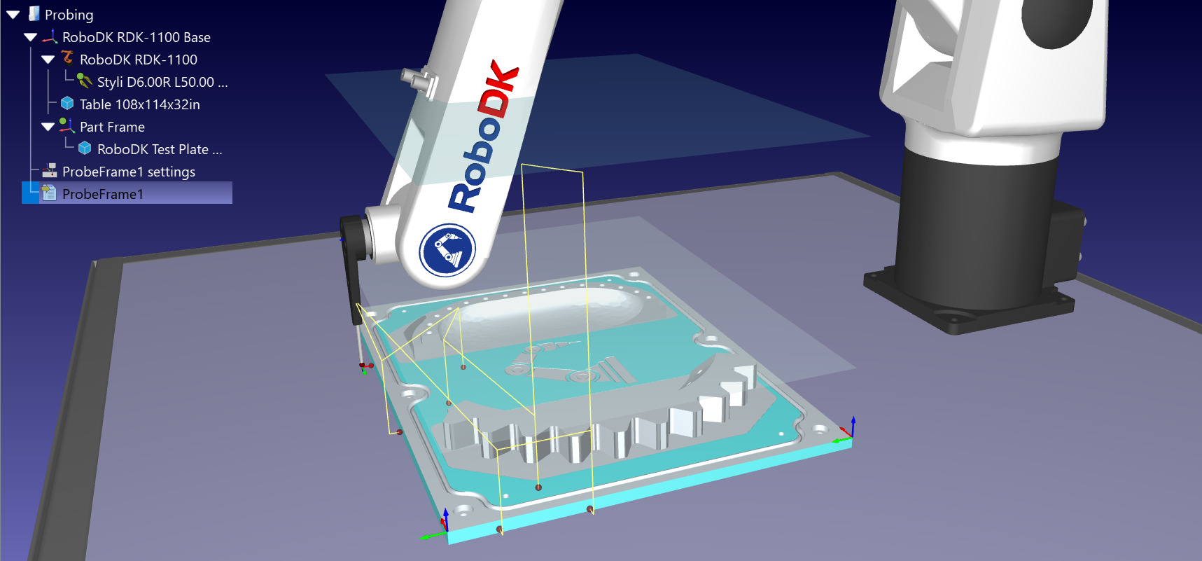
In the ProbeFrame1 settings window, click Simulate. Watch the robot move down, touch each point at probing speed, back off to the retract height and travel at the clearance height. Check that both heights clear every fixture and clamp, and adjust the settings before you run on the robot.
Generate Robot Program
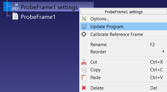
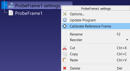
Click Update to generate the robot program for the probing sequence. You can also right-click the ProbeFrame1 settings item in the station tree and select Update Program. RoboDK creates (or replaces) a program named after the project without the word settings, for example ProbeFrame1, and places it right below the project item.
Calibrate Frame
Run the probing sequence and check that every Search Linear instruction came back with a green dot, then right-click the ProbeFrame1 settings item in the station tree and select Calibrate Reference Frame. RoboDK reads the contact position recorded by every search move, best-fits the datums again from those measured points, and compares the result with the nominal frame.
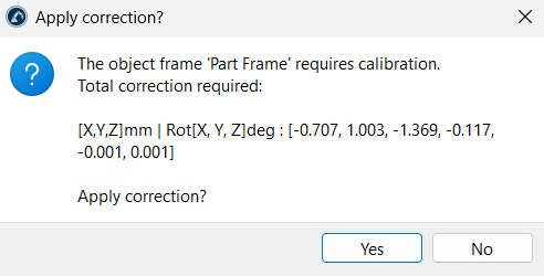
An Apply correction? dialog lists the total translation and rotation needed to match the measured part. Click Yes and RoboDK moves the part reference frame onto the measured position. If the correction is larger than the approach and overtravel distances combined, or if any rotation exceeds 30 degrees, the dialog warns you first — that usually means a point was probed on the wrong feature, so review the sequence instead of accepting it.