Troubleshooting Common Issues
Here are answers to common questions and error messages you might encounter:
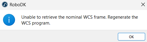
1.Unable to retrieve the nominal WCS frame. Regenerate the WCS program. You tried to calibrate before running the sequence. Run the generated ProbeFrame1 program first so that the contact data is recorded, then calibrate. If you changed any setting after the last run, generate and run the program again.
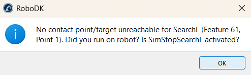
2.No contact point/target unreachable for Feature 3, Point 1. Did you run on robot? Is SimStopSearchL activated? No contact was recorded for that search move. If you are testing in simulation, check that Simulate touch probing contact with simulated collisions is enabled under Tools ➔ Options ➔ Drivers. If you ran on the robot, check that the driver reported the probe trigger back to RoboDK.
3.The probe is not approaching side faces correctly. By default every point is probed with the current tool orientation. Select the point in the ProbeFrame1 settings table and change its Tool Orient. value to X- or Y+, for example, so the probe tilts towards the side face. Increasing Approach and Overtravel can also help.
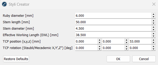
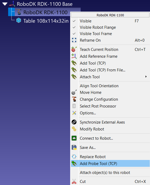
4.How do I create a custom probe stylus geometry? Select Probing ➔ Add Probe Tool (TCP), or right-click the robot and select Add Probe Tool (TCP). The Styli Creator window opens, where you enter the Ruby diameter [mm], Stem length [mm], Stem diameter [mm], Effective Working Length (EWL) [mm], TCP position (x,y,z) [mm] and TCP rotation (Staubli/Mecademic X,Y′,Z″) [deg]. The two TCP fields are pre-filled with the current TCP of the robot. RoboDK builds a stem-and-ruby model, names it after the values you entered (for example Styli D6.00R L50.00 EWL38.5 D4.5) and makes it the active tool of the robot. The EWL value only appears in the tool name; it does not change the geometry.