Visual Feedback
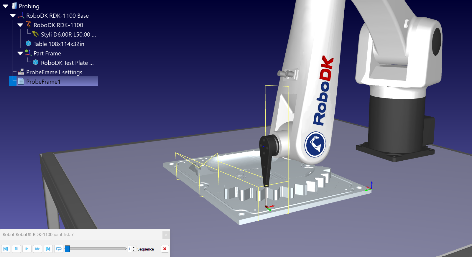
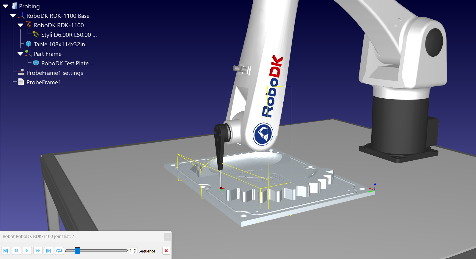
As you click around your 3D model to add points, RoboDK provides real-time visual feedback by changing the color of the surfaces:
1.Red: the surface has been detected as a feature but does not yet have enough contact points to resolve its geometry. Keep adding points.
2.Green: the feature is resolved. RoboDK was able to best-fit its geometry from your points, so it is a valid datum. Move on to the next feature.
3.Cyan: the feature is one of the three datums RoboDK is actually using to build the reference frame. Once three features are cyan the sequence is valid and you can simulate it and generate the program.
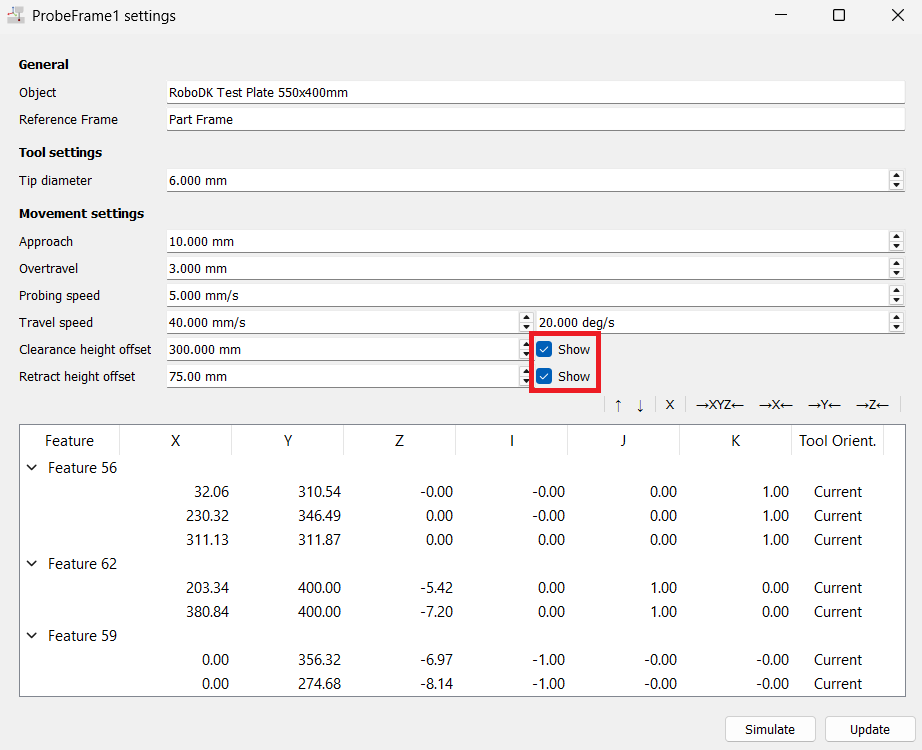
Select the Show checkbox next to Clearance height offset or Retract height offset to draw the corresponding plane in the 3D view. It is the quickest way to confirm that the robot travels above every clamp and fixture on the part.
Once the program has run — on the real robot through the driver, or in simulation with the option above enabled — RoboDK marks every Search Linear (SearchL) instruction that recorded a contact with a green dot. The green dot means the instruction holds a contact point, so you can display those points in the 3D view or read the joint values the robot stopped at. A Search Linear instruction without a green dot never registered a touch, which is what the No contact point/target unreachable error reports.
When you review the generated program you may want to check exactly where the probe touches the part, without reopening the editor. Right-click the ProbeFrame1 program and select Show Program Contact Points. The option is only useful after a run, because it replays the contact positions that were actually recorded.
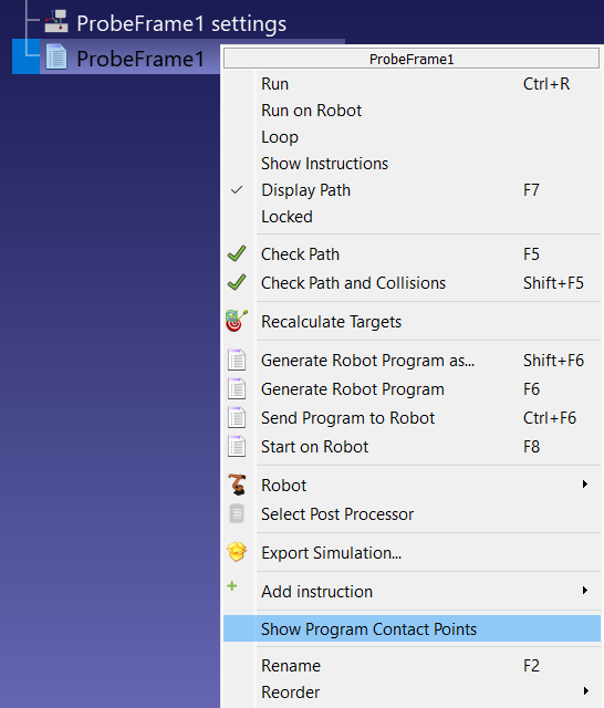
This option displays a slider in the RoboDK window, which you can use to verify each point’s spacing and alignment one by one.