Probing
The Probing Add-in for RoboDK helps you create custom probing routines directly in RoboDK. It supports the detection of features such as planes, cylinders and spheres, for generating probing sequences that align parts or calibrate robot reference frames. The probing sequence can be triggered directly from RoboDK and executed on the real robot through the RoboDK driver, without exporting a program file, provided the driver supports touch probe integration.
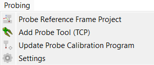
After installing the Probing Add-in, go to Tools ➔ Add-in Manager (or press Shift+A) and Enable the Add-in. You can now find its features in the Probing menu.
Requirements
Probing is built around a touch-trigger probe mounted on the robot, and a controller able to read its signal. Everything else depends on how the probing program reaches the robot. Select Probing ➔ Settings and set Probing style before you build your first project:
1.RoboDK is the default. The probing moves are generated as Search Linear (SearchL) instructions and you trigger the sequence directly from RoboDK: the robot driver runs it on the real robot, stops the motion when the probe triggers, and reports the contact position back to RoboDK, which is what Calibrate Reference Frame reads afterwards. This style requires a RoboDK driver with touch probe integration for your robot.
2.The six Renishaw entries (for ABB, Fanuc, KUKA, Yaskawa, Mitsubishi and Staubli) generate Renishaw Daytona macro calls instead. The program is exported with your post processor and transferred to the controller, where the Renishaw macros perform the touches and compute the alignment.
Creating a Probing Project
Set up your RoboDK station with the robot, the probe tool and the part you want to measure. The part must belong to a dedicated reference frame: place the object directly under that frame, leave it at the exact origin of the frame, and make sure the frame is not the robot base. Calibration works by moving that reference frame, so the part itself must not carry a pose of its own.
Select Probing ➔ Probe Reference Frame Project in the menu bar, or click the matching button in the toolbar. RoboDK adds a ProbeFrame1 settings item to the station tree and opens its editor window.
The editor groups the probing sequence settings in three sections:
1.General shows the Object being probed and its Reference Frame. Both fields are read-only; they are filled in automatically when you click the part to add your first probing point.
2.Tool settings holds Tip diameter, the diameter of the ruby at the tip of your stylus (6 mm by default). Enter the exact value: RoboDK offsets every surface point by half of it along the surface normal to obtain the tool contact point, so a wrong diameter shifts every measurement.
3.Movement settings holds the distances, speeds and heights used around each point:
a.Approach (10 mm by default, 2 to 100 mm) is the distance in front of the surface where the probe switches from travel speed to probing speed.
b.Overtravel (3 mm by default, 0 to 100 mm) is how far past the expected contact point the probe keeps searching, so contact is still made when the real part sits slightly away from its nominal position.
c.Probing speed (5 mm/s by default) is the slow linear speed used while searching for contact. Keep it low to protect the probe and improve repeatability.
d.Travel speed (40 mm/s and 20 deg/s by default) is used for the moves in free air between points.
e.Clearance height offset (300 mm by default) is the height the robot travels at before the first point and after the last point of the whole sequence.
f.Retract height offset (75 mm by default) is the height the probe backs off to between two points, within a feature as well as between features.
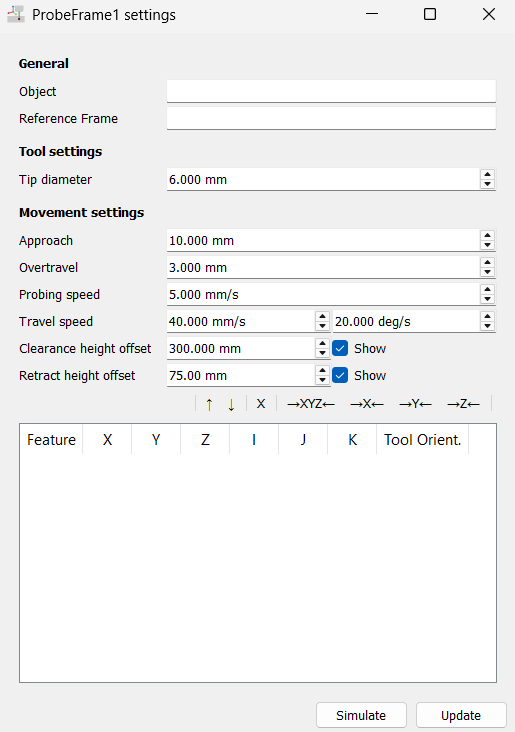
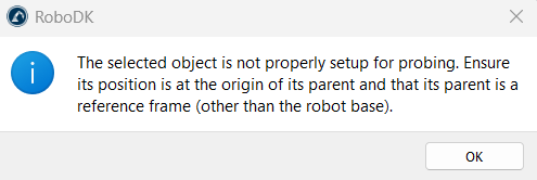
Click your object, such as a part or a fixture, to create a first probing point. Doing so fills in the two read-only General fields of the ProbeFrame1 settings window:
1.Object
2.Reference Frame
Optimizing the Probing Project
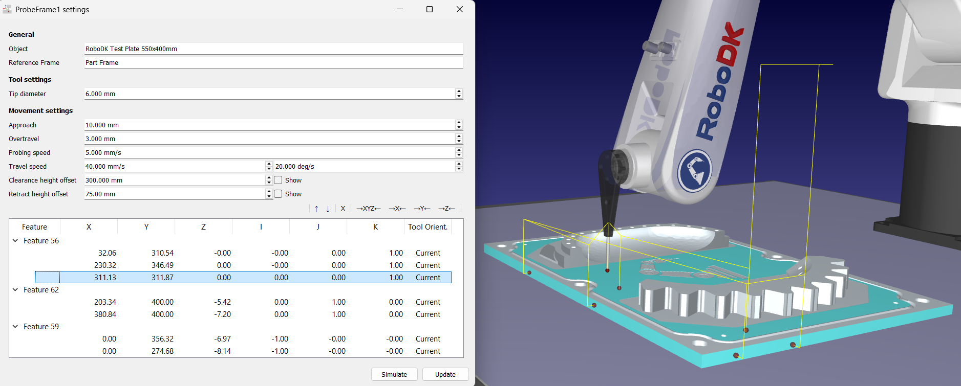
The Add-in detects the geometry under each surface you click and best-fits it as a datum: a point, a line, a plane, a cylinder or a sphere. Every type needs a minimum number of contact points before its geometry can be resolved: 1 for a point, 2 for a line, 3 for a plane, 4 for a sphere and 5 for a cylinder. A reference frame needs three datums, taken in the order they appear in the feature list. These are the combinations RoboDK can turn into a frame:
1.Plane, Line, Point: 3 points on a face, 2 points along an edge and 1 point to set the origin. This is the classic 3-2-1 alignment and the quickest one to probe.
2.Plane, Plane, Plane: 3 points on each of three faces that are not parallel to one another.
3.Plane, Plane, Point: 3 points on each of two faces, plus 1 point for the remaining origin component.
4.Plane, Cylinder, Cylinder: 3 points on a face and 5 points inside each of two bores.
5.Sphere, Sphere, Sphere: 4 points on each of three calibration spheres.
Feature Controls
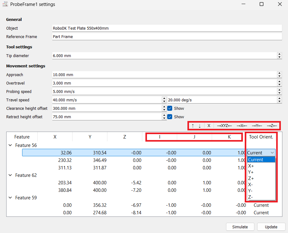
Simply click on the surface of the object to add new points. You can also:
1.Re-order points using the Up/Down arrows. This modifies the probing sequence and can help the robot take the most efficient path.
2.Delete an existing point or feature from the list using the X button.
3.Center the point on the surface along X, Y, Z, or all three axes.
4.Adjust direction vectors (IJK).
5.Set the tool orientation used to approach each point, in the Tool Orient. column. Current is the default and keeps the orientation the robot has when the program is generated; X+, X-, Y+, Y-, Z+ and Z- align that tool axis with the probing direction, which is what you need for points on a side face.
Visual Feedback
As you click around your 3D model to add points, RoboDK provides real-time visual feedback by changing the color of the surfaces:
1.Red: the surface has been detected as a feature but does not yet have enough contact points to resolve its geometry. Keep adding points.
2.Green: the feature is resolved. RoboDK was able to best-fit its geometry from your points, so it is a valid datum. Move on to the next feature.
3.Cyan: the feature is one of the three datums RoboDK is actually using to build the reference frame. Once three features are cyan the sequence is valid and you can simulate it and generate the program.
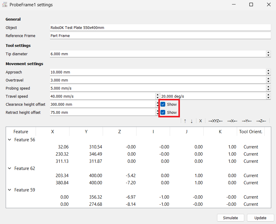
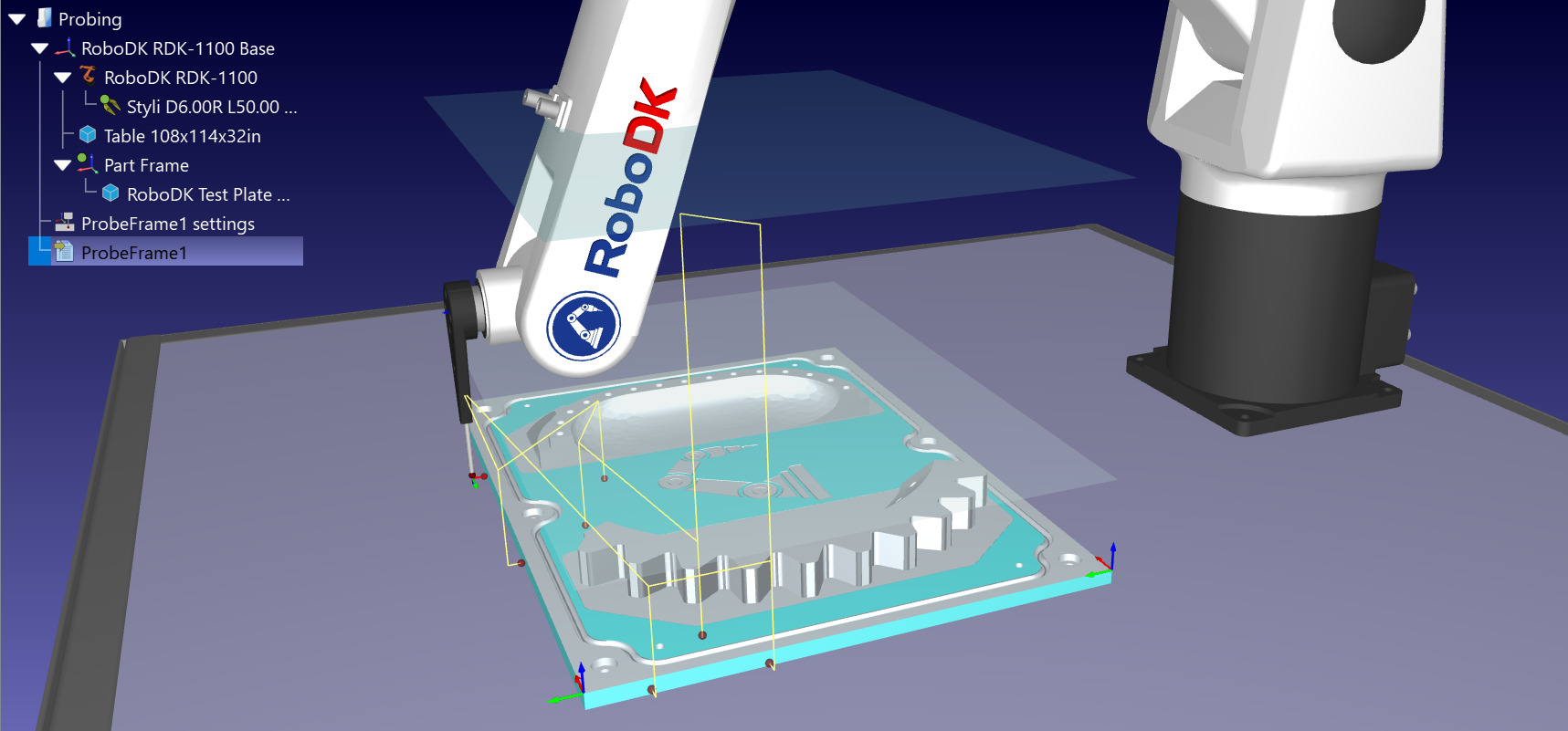
Select the Show checkbox next to Clearance height offset or Retract height offset to draw the corresponding plane in the 3D view. It is the quickest way to confirm that the robot travels above every clamp and fixture on the part.
Once the program has run — on the real robot through the driver, or in simulation with the option above enabled — RoboDK marks every Search Linear (SearchL) instruction that recorded a contact with a green dot. The green dot means the instruction holds a contact point, so you can display those points in the 3D view or read the joint values the robot stopped at. A Search Linear instruction without a green dot never registered a touch, which is what the No contact point/target unreachable error reports.
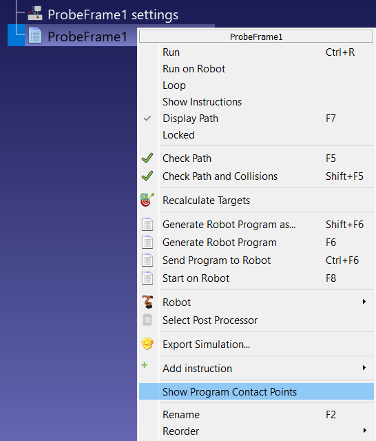
When you review the generated program you may want to check exactly where the probe touches the part, without reopening the editor. Right-click the ProbeFrame1 program and select Show Program Contact Points. The option is only useful after a run, because it replays the contact positions that were actually recorded.
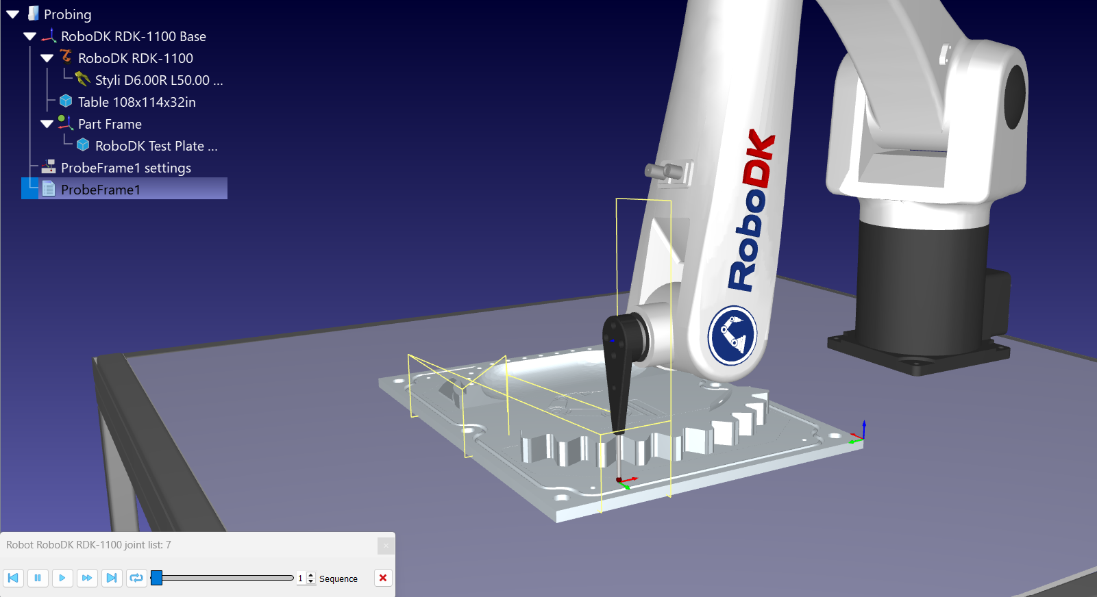
This option displays a slider in the RoboDK window, which you can use to verify each point’s spacing and alignment one by one.
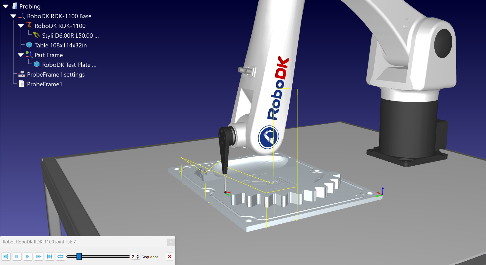
Final Run
Now that all the points are defined, the remaining steps are to simulate the sequence, generate the robot program and calibrate the reference frame.
Enable Simulated Probing
To test the routine without a real probe, let RoboDK simulate the trigger. Select Tools ➔ Options ➔ Drivers, select Simulate touch probing contact with simulated collisions and click OK. The search moves then stop on the simulated contact between the probe and the part; the Add-in enables that collision pair for you when it generates the program.
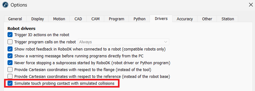
Preview the Simulation
In the ProbeFrame1 settings window, click Simulate. Watch the robot move down, touch each point at probing speed, back off to the retract height and travel at the clearance height. Check that both heights clear every fixture and clamp, and adjust the settings before you run on the robot.
Generate Robot Program
Click Update to generate the robot program for the probing sequence. You can also right-click the ProbeFrame1 settings item in the station tree and select Update Program. RoboDK creates (or replaces) a program named after the project without the word settings, for example ProbeFrame1, and places it right below the project item.
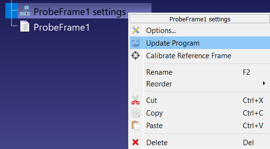
Calibrate Frame
Run the probing sequence and check that every Search Linear instruction came back with a green dot, then right-click the ProbeFrame1 settings item in the station tree and select Calibrate Reference Frame. RoboDK reads the contact position recorded by every search move, best-fits the datums again from those measured points, and compares the result with the nominal frame.
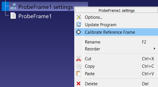
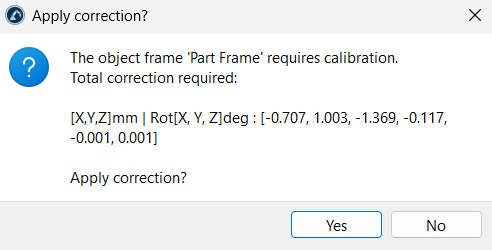
An Apply correction? dialog lists the total translation and rotation needed to match the measured part. Click Yes and RoboDK moves the part reference frame onto the measured position. If the correction is larger than the approach and overtravel distances combined, or if any rotation exceeds 30 degrees, the dialog warns you first — that usually means a point was probed on the wrong feature, so review the sequence instead of accepting it.
Calibrate the Probe TCP
Besides aligning a part, the Add-in can generate a program that calibrates the TCP of the probe itself against a calibration sphere. Add the sphere to the station, probe it as a feature of your project, and add at least one point on the side of the sphere opposite to the stem so that the probe approaches it straight along the stem axis.
Select Probing ➔ Update Probe Calibration Program. RoboDK uses the nominal diameter of the sphere and generates a second program named after the project, for example ProbeFrame1 Probe Calibration.
Troubleshooting Common Issues
Here are answers to common questions and error messages you might encounter:
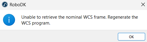
1.Unable to retrieve the nominal WCS frame. Regenerate the WCS program. You tried to calibrate before running the sequence. Run the generated ProbeFrame1 program first so that the contact data is recorded, then calibrate. If you changed any setting after the last run, generate and run the program again.
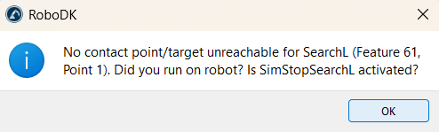
2.No contact point/target unreachable for Feature 3, Point 1. Did you run on robot? Is SimStopSearchL activated? No contact was recorded for that search move. If you are testing in simulation, check that Simulate touch probing contact with simulated collisions is enabled under Tools ➔ Options ➔ Drivers. If you ran on the robot, check that the driver reported the probe trigger back to RoboDK.
3.The probe is not approaching side faces correctly. By default every point is probed with the current tool orientation. Select the point in the ProbeFrame1 settings table and change its Tool Orient. value to X- or Y+, for example, so the probe tilts towards the side face. Increasing Approach and Overtravel can also help.
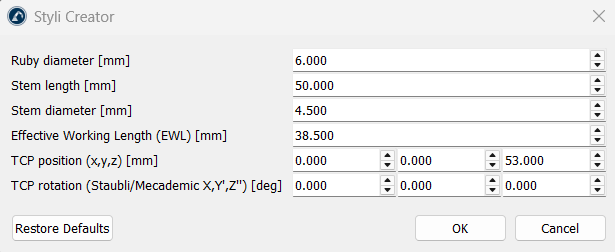
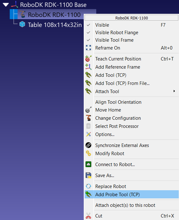
4.How do I create a custom probe stylus geometry? Select Probing ➔ Add Probe Tool (TCP), or right-click the robot and select Add Probe Tool (TCP). The Styli Creator window opens, where you enter the Ruby diameter [mm], Stem length [mm], Stem diameter [mm], Effective Working Length (EWL) [mm], TCP position (x,y,z) [mm] and TCP rotation (Staubli/Mecademic X,Y′,Z″) [deg]. The two TCP fields are pre-filled with the current TCP of the robot. RoboDK builds a stem-and-ruby model, names it after the values you entered (for example Styli D6.00R L50.00 EWL38.5 D4.5) and makes it the active tool of the robot. The EWL value only appears in the tool name; it does not change the geometry.
Additional Options and Settings
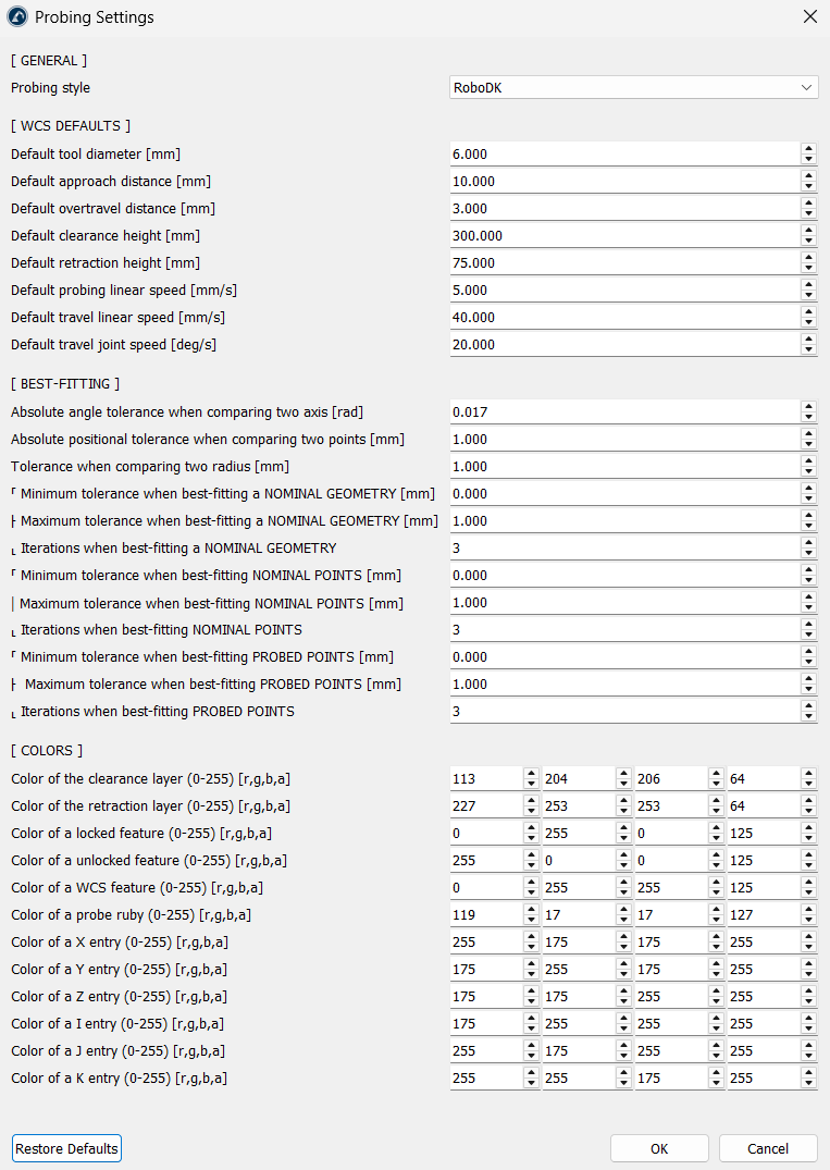
RoboDK provides a global Probing Settings window. Select Probing ➔ Settings to open it. The values you set here are the defaults used whenever you start a new probing project; they do not change projects that already exist. Click Restore Defaults to go back to the standard values.
General
Probing style selects how probing routines are written. RoboDK is the default and generates search instructions executed through a robot driver. The six Renishaw entries (for ABB, Fanuc, KUKA, Yaskawa, Mitsubishi and Staubli) generate Renishaw Daytona macro calls for the matching controller.

WCS Defaults
Instead of editing distances and other parameters manually every time you build a project, these values automatically pre-populate your project settings:
1.Default tool diameter [mm]: the ruby diameter at the probe tip. Default: 6 mm.
2.Default approach distance [mm]: the distance at which the probe slows down in front of a surface. Default: 10 mm.
3.Default overtravel distance [mm]: the extra search depth past the expected surface. Default: 3 mm.
4.Default clearance height [mm]: the safe height used before the first point and after the last point. Default: 300 mm.
5.Default retraction height [mm]: the height the probe backs off to between points. Default: 75 mm.
6.Default probing linear speed [mm/s]: the touch-sensing search speed. Default: 5 mm/s.
7.Default travel linear speed [mm/s]: the linear speed in free air. Default: 40 mm/s.
8.Default travel joint speed [deg/s]: the joint speed for travel moves. Default: 20 deg/s.
Best-Fitting
These parameters control how RoboDK mathematically aligns measured points to nominal CAD geometry:
1.Absolute angle tolerance when comparing two axes [rad]: The maximum angular deviation allowed when matching feature axes.
2.Absolute positional tolerance when comparing two points [mm]: The maximum positional error allowed between probed and nominal points.
3.Tolerance when comparing two radius [mm]: The maximum allowed difference when matching measured hole or sphere radii to CAD models.
4.Best-Fitting Tolerances and Iterations: These define the minimum tolerance, maximum tolerance, and iteration limit when best-fitting Nominal Geometry, Nominal Points, and Probed Points.
Colors
1.Clearance and Retraction Layers: You can adjust the transparency and color of the safe movement planes.
2.Feature States: You can also customize colors for locked, unlocked, and WCS features.
3.Probe Ruby: You can change the color of the probe stylus tip.
4.Coordinate and Vector Indicators: You can assign distinct colors for X, Y, Z positions and I, J, K approach vector fields which are visible in the settings table.


