Safety Zones
The Safety Zones Add-in for RoboDK allows you to define robot safety boundaries and automatically generate the corresponding controller configuration files. It bridges the gap between 3D simulation and hardware safety setup by letting you visualize workspaces in RoboDK and export them directly to supported industrial robot controllers.
A typical workflow is: create the safety geometry, link the geometry to a robot workspace, generate the safety instructions, and enable or disable those workspaces as needed in the robot program.
The Add-in is organized under the Safety Zones menu.
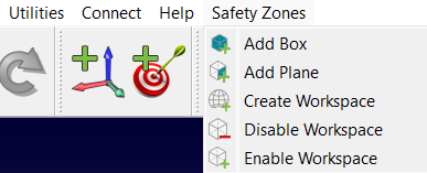
You can also find a dedicated toolbar for quick access.

Creating Safety Geometry
Before defining a workspace, you must create the physical shapes that represent the safety volumes. The add-in provides two primary tools for this:
Add Box
This tool creates a 3D box used to define a volumetric safety zone.
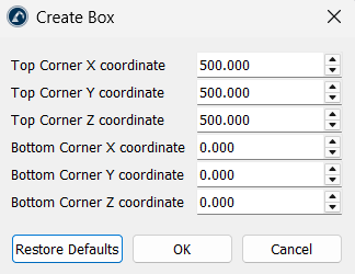
1.Corner Coordinates: Define the zone by entering the Top Corner and Bottom Corner coordinates in X, Y, and Z. These two points define the opposite corners of the 3D box.
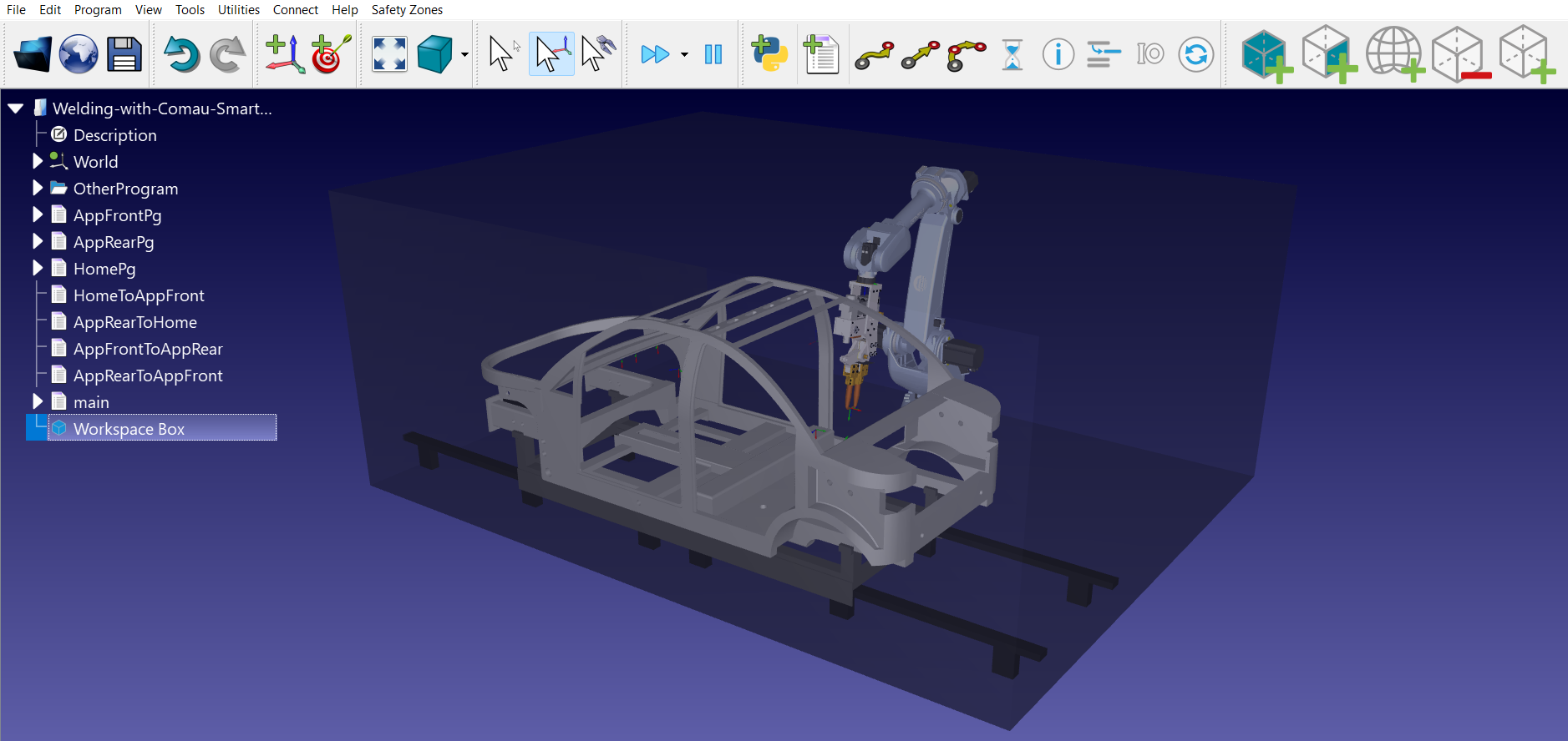
2.Visual Setup: The script automatically generates a semi-transparent gray object named "Workspace Box".
Add Plane
This user interface allows you to create a 2D planar boundary within the robot environment.
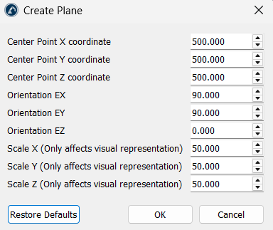
The following parameters are important:
1.Positioning: Specify a Center Point (X, Y, Z) and the Orientation (EX, EY, EZ) of the plane.
2.Scaling: You can adjust the visual scale (X, Y, Z) to make the plane easier to see in the simulation.
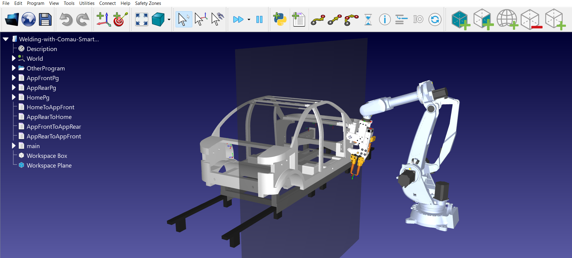
Setting Up the Workspace
Once the geometry is defined, link it to a robot and a program so the add-in can generate the corresponding safety instructions.
Create Workspace
The Create Workspace tool converts your station objects into functional safety instructions.
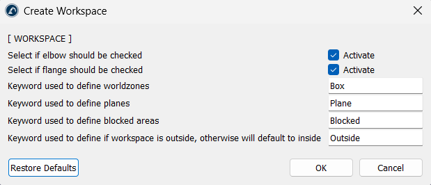
The script automatically identifies items in the station based on their names. Make use of keywords to define the following:
1.World zones (default: "Box")
2.Planes (default: "Plane")
3.Blocked areas (default: "Blocked")
4.Blocked areas identify volumes that the robot should avoid, while the Outside keyword reverses the zone logic so the safe area is outside the selected volume instead of inside it.
If there is a need to monitor the robot’s elbow or flange to check whether it enters the forbidden zone, click on the corresponding "Activate" checkbox.
The tool generates a program called AddWorkspaces and adds a call to it in the program you select.
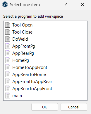
Enable and Disable Workspace
Safety zones can be turned on or off during a robot's operation using the following utilities:
1.Enable Workspace: Adds an instruction to the program to turn on a specific safety zone.
2.Disable Workspace: Adds an instruction to turn off a specific zone when it is no longer needed for a task.
Tips and Best Practices
We recommend you follow these best practices when using the Safety Zones Add-in.
1.Ensure that the workspace objects include correct keywords ("Box", "Plane", "Blocked") so the add-in can find them automatically.
2.If a post-processor does not support safety zones, RoboDK will show a message accordingly.
3.When creating a workspace, the tool will ask you to select a reference frame. It is best to use a consistent frame so the coordinates exported to the controller match your physical setup.
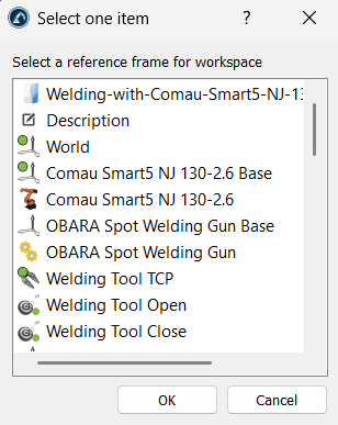
4.Always make the virtual safety boxes slightly larger than the real-world obstacles to account for small calibration differences between the simulation and the real robot.


