Surface Pattern Generator
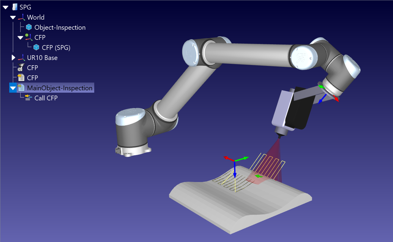
The Surface Pattern Generator Add-in projects structured path layouts directly onto 3D object geometries. Instead of sketching points manually, this Add-in uses local reference frames to cast customized geometric paths, such as parallel grids, triangles, or continuous zig-zag runs, straight onto a target surface.
This Add-in provides automated path mapping for operations like industrial spray painting, surface polishing, structural welding, or area scanning, and links the generated shapes to a Curve Follow Project automatically.
You can install the Surface Pattern Generator Add-in from the RoboDK Add-in Marketplace in the Online Library. Another way to do this from RoboDK software itself is by going to Tools ➔ Add-in Manager (or press Shift+A) and Enable the Surface Pattern Generator Add-in.
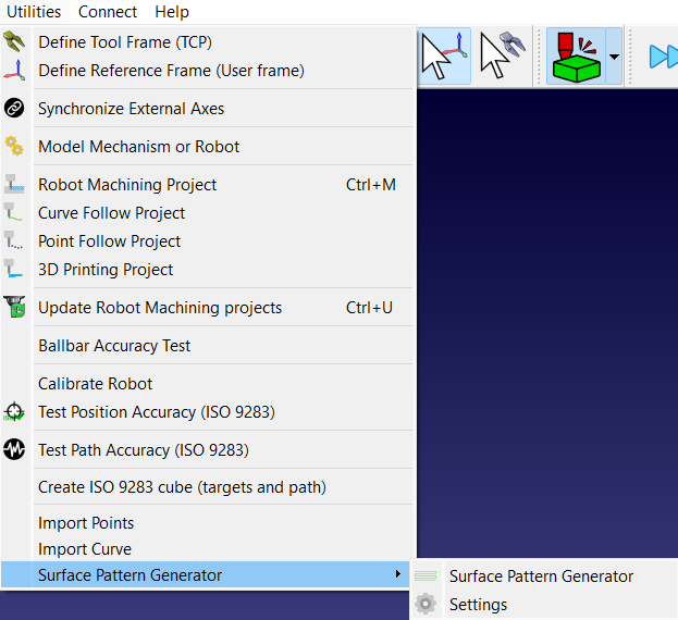
After installing the Add-in, you can find it under Utilities ➔ Surface Pattern Generator. The corresponding icon is also present in the toolbar for quick access.
Setup Requirements
The RoboDK station must be organized with the following elements in order to work with the Surface Pattern Generator Add-in:
1.Object: At least one 3D model must be loaded into the station tree.
2.Reference Frames: The project requires one or more standard reference frames placed at the same tree level as the part. It should also have the same name as the desired name for the Curve Follow Project.
3.Frame Alignment: The reference frame must be oriented so that its Z-axis points directly toward the part surface. The X and Y axes establish the outer direction alignment for the grid pattern.
Parameter Settings
The configurations determine how the projection layout is built, scaled, and spaced across the face of the part.
Pattern Layout Dimensions
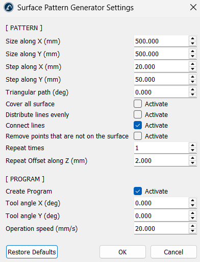
1.Size along X (mm) and Size along Y (mm): Controls the overall width and length boundaries of the projection area starting from the source frame origin.
2.Step along X (mm) and Step along Y (mm): Defines the resolution gap. The X step determines the distance between parallel passes, while the Y step dictates how close together individual calculation markers are dropped along each line.
3.Triangular path (deg): Setting an angle greater than zero pulls the outer boundary edges inward. This morphs a standard rectangular grid into a clean, tapered triangular pattern.
Distribution and Connection Rules
1.Cover all surface: When checked, it forces the calculation loop to extend all the way to the maximum boundary limits, ensuring no edges are left short if the sizing steps do not divide evenly.
2.Distribute lines evenly: When activated, it dynamically resizes the gap between lines so every pass is spaced perfectly across the chosen area without leaving an uneven gap at the final edge.
3.Connect lines: Joins individual parallel lines together at their ends into a single, uninterrupted zig-zag path, preventing the robot from constantly lifting and resetting between rows. This setting is kept on by default.
4.Remove points that are not on the surface: This filters out calculation markers that miss the target geometry entirely. When active, lines that fall off the edges or pass through hollow cutouts/holes are deleted automatically rather than creating floating air-paths.
Multi-Pass Offsets
1.Repeat times: Sets the total number of identical path layers to generate.
2.Repeat Offset along Z (mm): Sets a vertical spacing distance for each extra layer. This creates parallel multi-pass layers stacked along the Z-axis, which helps when programming layered material deposition or multi-stage surface treatments.
Program Integration
1.Create Program: Automatically generates a functional motion program alongside the raw geometry lines. It is on by default.
2.Tool angle X (deg) and Tool angle Y (deg): Tilts the orientation angle of the robot's TCP relative to the surface normal, allowing for fixed nozzle angles or custom torch tilts during execution.
3.Operation speed (mm/s): Injects a uniform linear travel speed limit straight into the motion parameters.
Usage
The Surface Pattern Generator Add-in acts as a one-click-solution to generate robot tool paths with only the part object. Follow the steps below to use this Add-in:
1.Open the station file and position a target frame facing the part surface.
2.Click on the Surface Pattern Generator icon on the toolbar.
3.Select the target part model in the popup prompt (appears only if there is more than one object item in the station).
4.Adjust sizes, step gaps, and connection toggles inside the settings panel.
5.Click OK to process.
The Add-in generates a geometric line object under the target frame we added in the first step, creates a Curve Follow Project, solves the toolpaths, and compiles a main program sequence automatically.