Welding Interface
This section covers the available functionalities of the user interface of the welding Add-in.
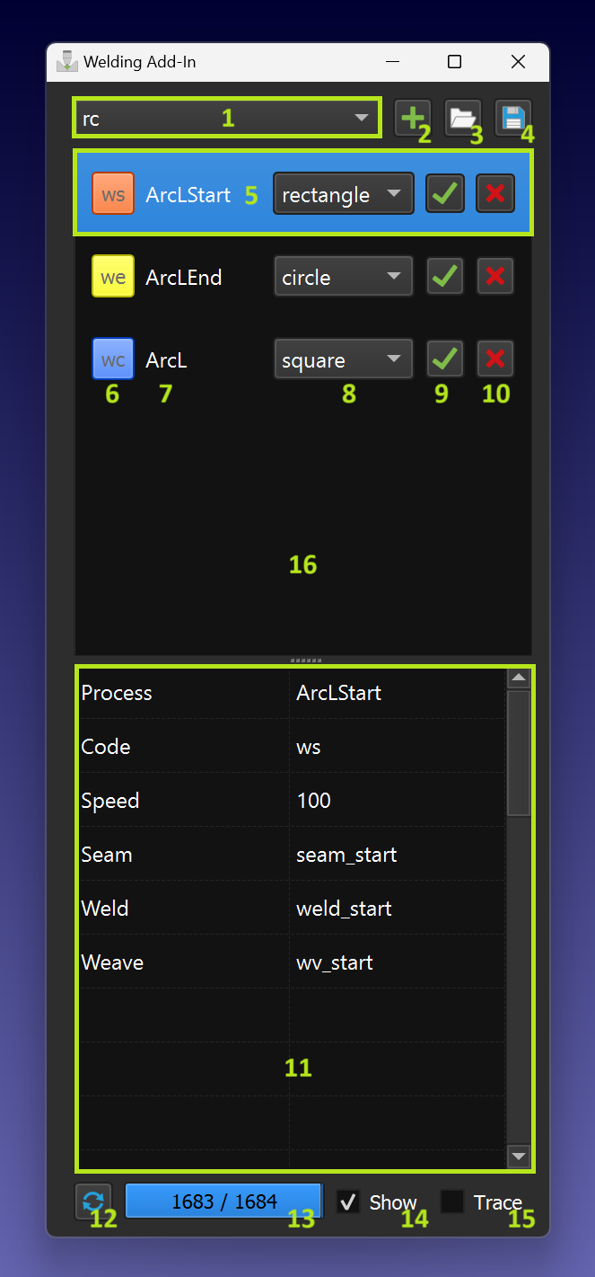
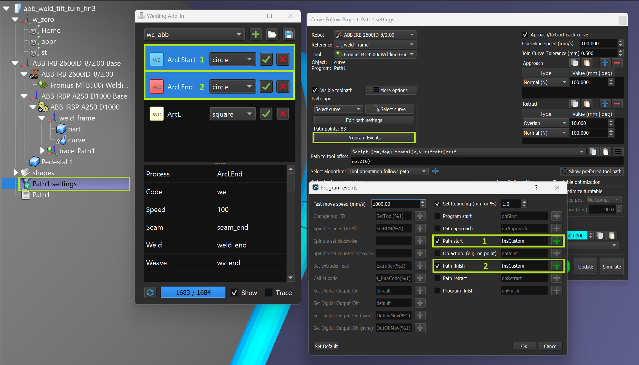
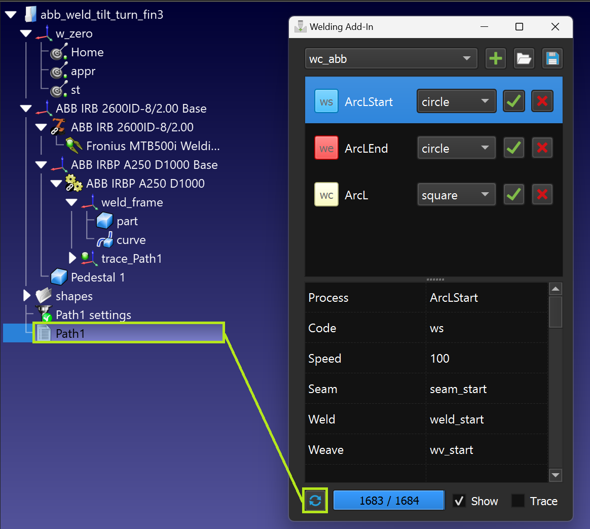
The Welding Add-In contains the following functional elements:
1.Instruction selection pull-down menu.
2.Instruction adding to the instructions list.
3.Import instructions list.
4.Export instructions list.
5.Current instruction (selected).
6.Instruction code and icon color (click to change color).
7.Instruction name (unique).
8.Appropriate path shape.
9.Add instructions to the program sequence or CFP.
10.Delete instructions from the list.
11.Parameters linked to the selected instructions.
12.Build a path model.
13.Path model building progress.
14.Path model visibility flag.
15.Path trace flag (allows simulate material’s adding).
16.Instructions list area.
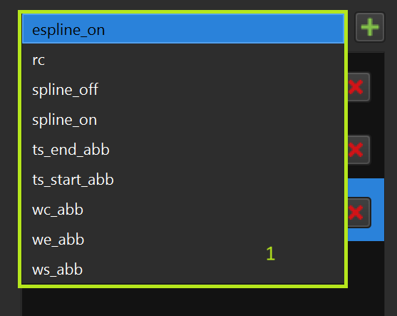
Instruction selection pull-down menu
You can select the instruction to be added from the pull-down menu:
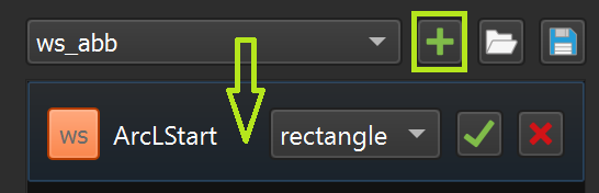
Adding an instruction to the instruction list
You can add the selected instruction from the pull-down menu using the '+' button:
The instruction templates are in the following folder (default RoboDK installation):
C:\RoboDK\Addins\com.robodk.app.welding\WeldingAddIn\templates
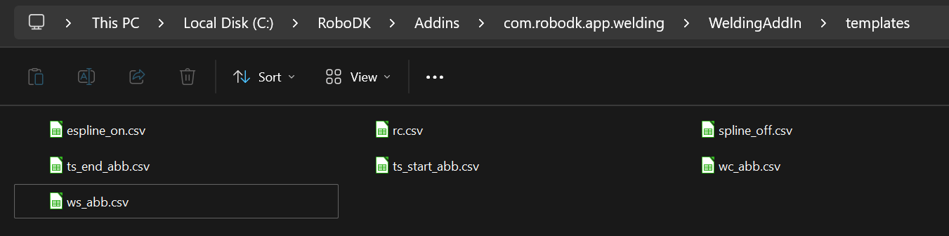
Templates are presented as regular '.csv' files with the string format 'parameter->value':
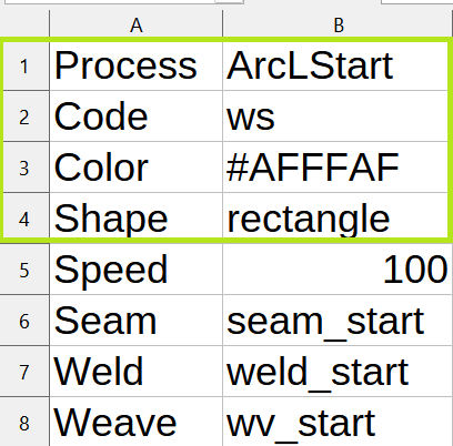
1.‘Process’ ➔ ‘Process name’ (some name should be specified)
2.‘Code’ ➔ ‘Instruction code’ (one of the supported instruction codes)
3.‘Color’ ➔ any color code in the hex format
4.‘Shape’ ➔ file name with the shape model for the welding instructions
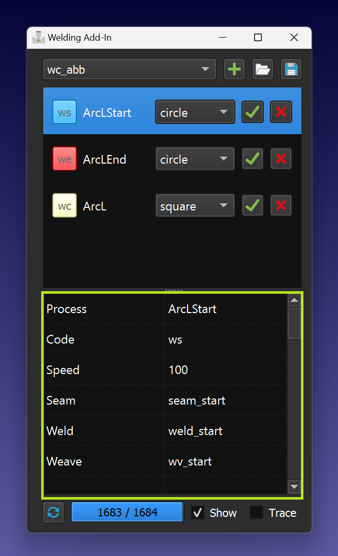
Current instruction (selected)
You can access the parameters by selecting a line in the instruction list (9). In addition, the instruction line is highlighted automatically during program execution or when the corresponding program instruction is double clicked:
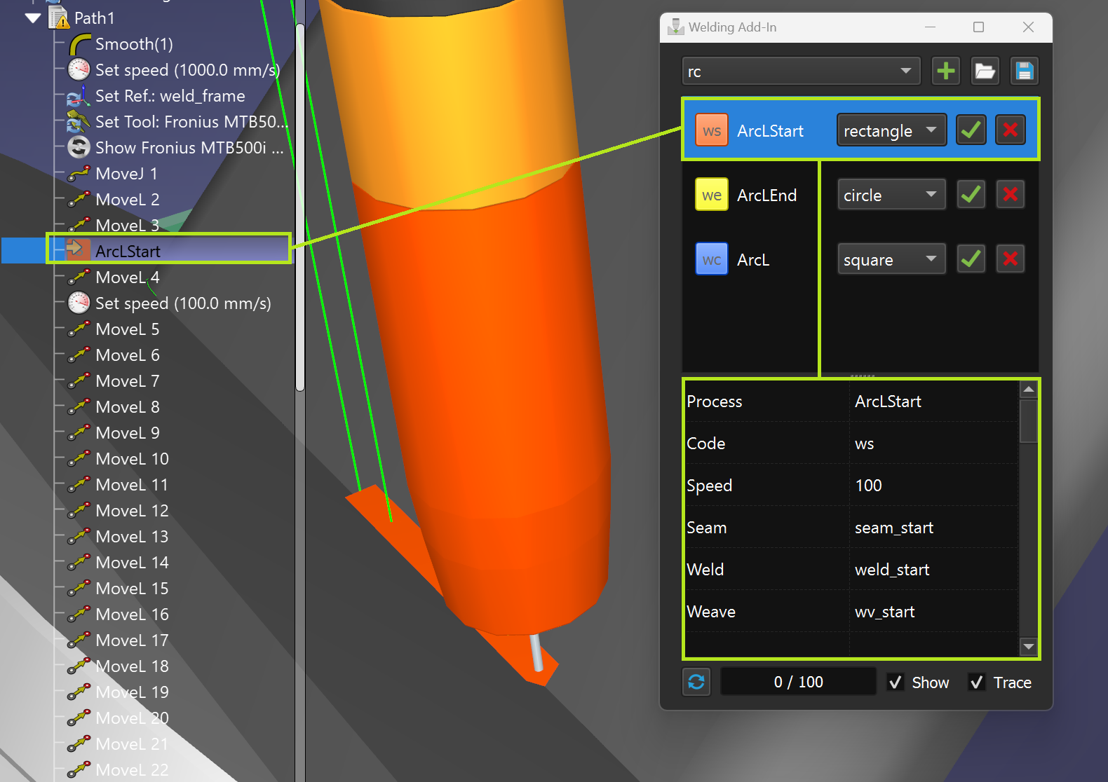
Instruction code & icon color
You can set the color of the instruction and the corresponding path by clicking on the instruction code button (make sure that the instruction line is selected first):
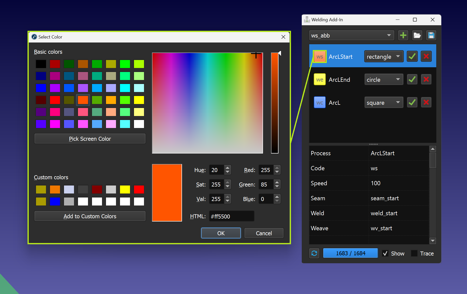
1.ws – welding start instruction
2.wc – welding continue instruction
3.we – welding end instruction
4.rc – custom Insert Code instruction
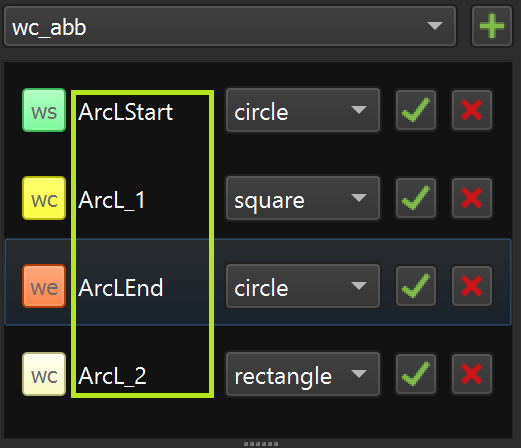
Instruction name
Every instruction in the instruction list should have a unique name (value of the 'Process' parameter):
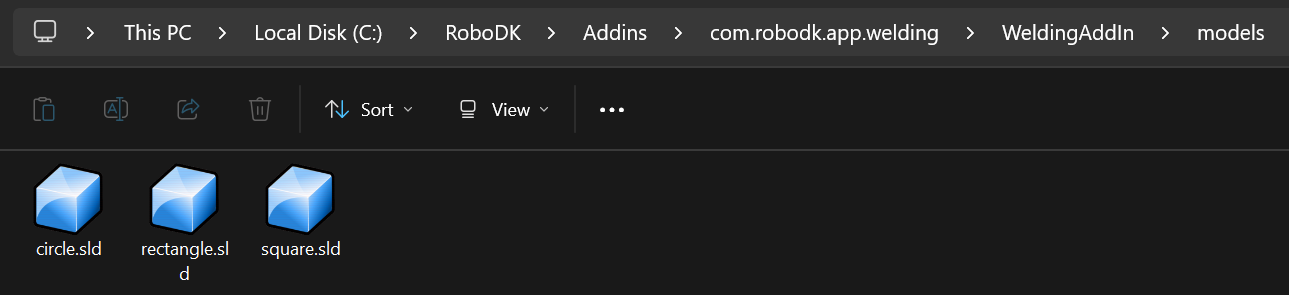
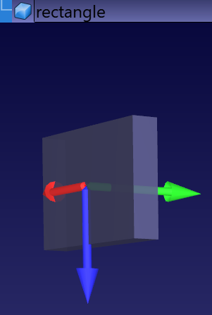
Path shape
If the instruction template has a path shape definition, it can be selected from the pull-down menu:
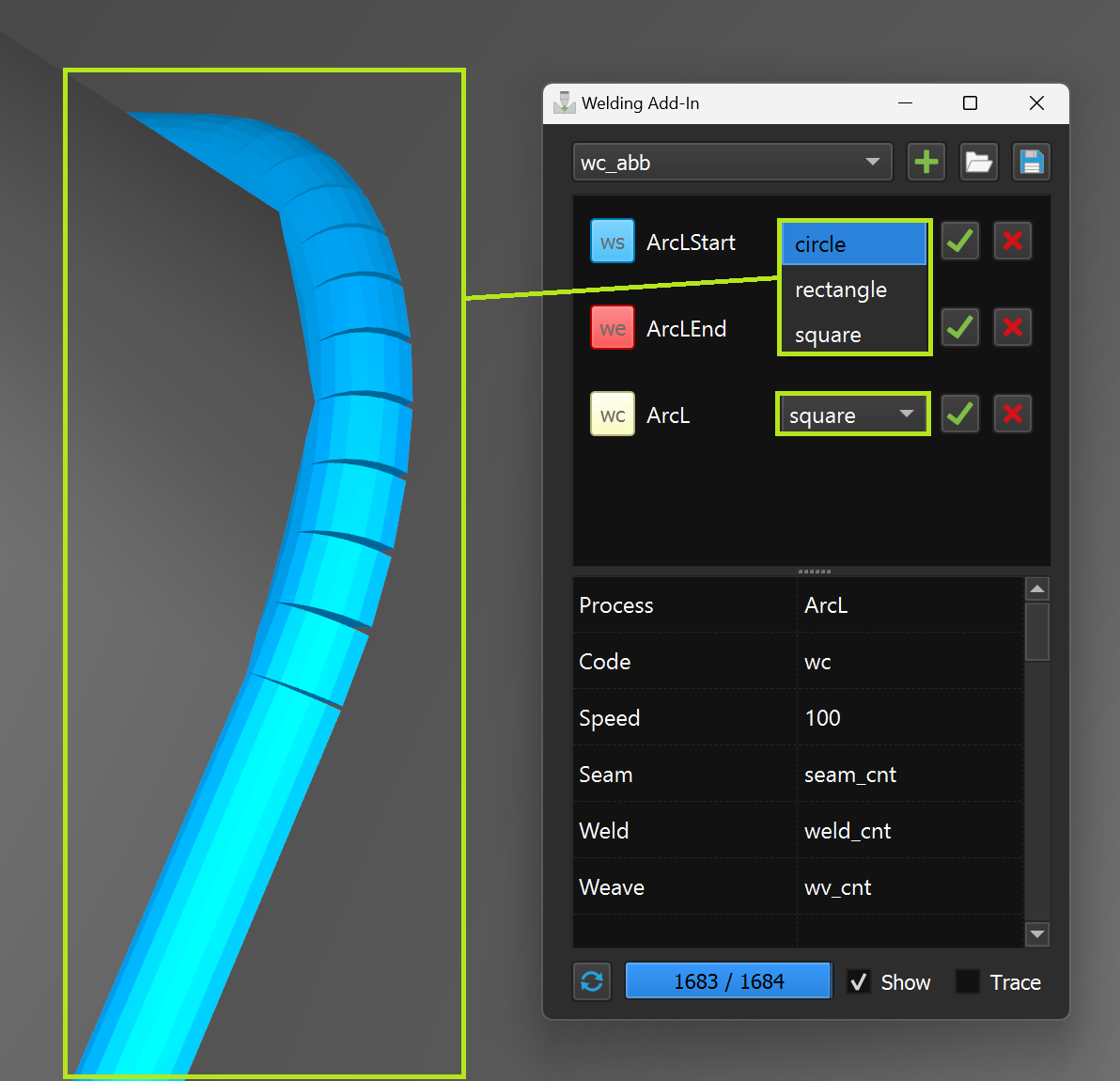
C:\RoboDK\Addins\com.robodk.app.welding\WeldingAddIn\models
Add instructions to the program sequence
A single instruction or a pair of sequentially selected instructions can be added to a RoboDK program sequence.
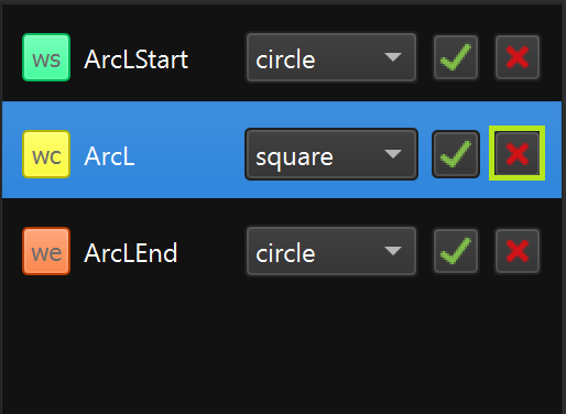
Delete instruction from the list
You can delete an instruction from the instruction list by clicking the “X” button.
Parameters
You can change parameters directly in the parameter table. The changes can be saved automatically.
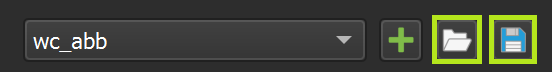
Parameters import/export
You can import the entire list of instructions with parameters or export all data using the import/export functions.
Path building
You can build the path using the 'Build' function for the selected program (it needs to contain welding instructions).
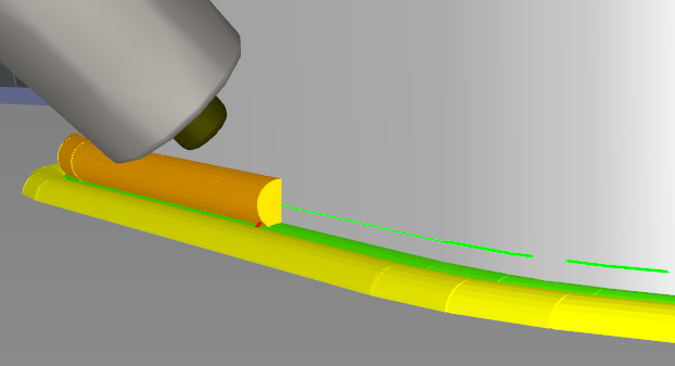
Path tracing
By enabling the "Trace" option, it is possible to see how the welding material is applied as the robot is moving along the welding path.