Toolpath strategies
RoboDK CAM allows you to use machining strategies such as surface machining, drilling, roughing, and others. In addition, you can simulate the material removal process.
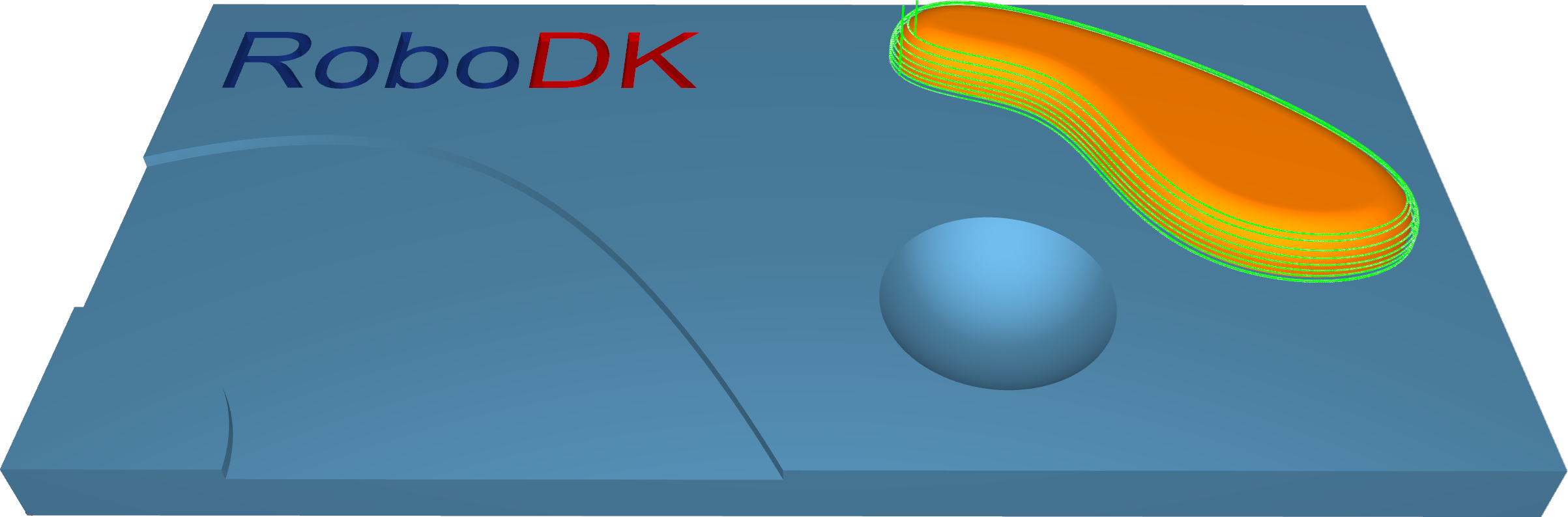
Surfaces–Parallel cuts
The Parallel Cuts option creates a toolpath pattern with parallel slices. The orientation of the slices is defined by two angles: X-Y (which rotates the slices around the Z axis) and Z. Imagine slicing an apple: You can slice it with a knife parallel from top to bottom or from left side to right side. The pictures in the dialog symbolize how to set the desired cutting direction using the angles.

Station: CAM-Surfaces-ParallelCuts.
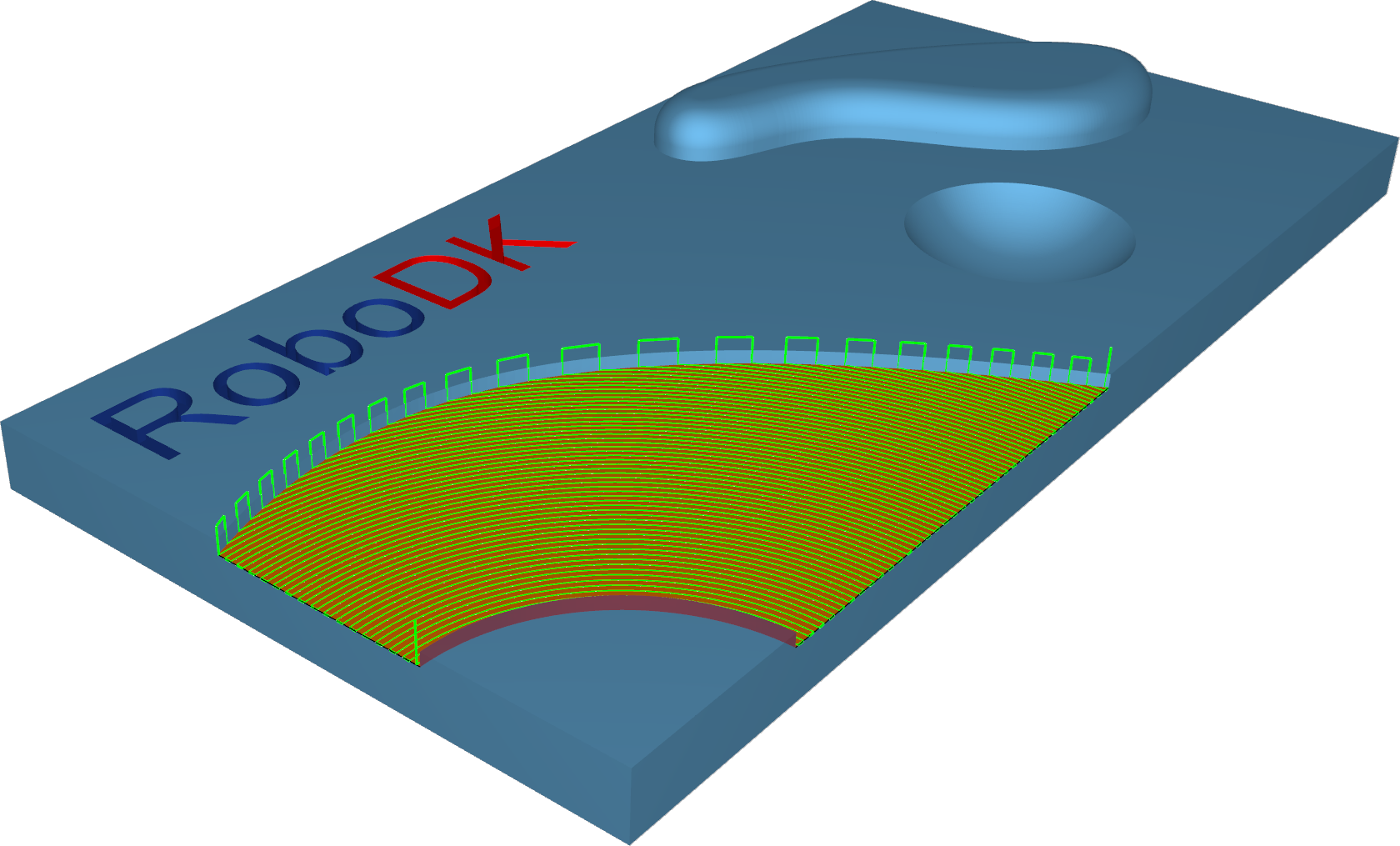
Surfaces–Cuts along curve
The Cuts along curve pattern allows the user to create a toolpath orthogonal to a drive curve. That means that if the selected curve as 'Lead' is not a straight line, the cuts are not parallel to each other.
Station: CAM-Surfaces-CutAlongCurve.
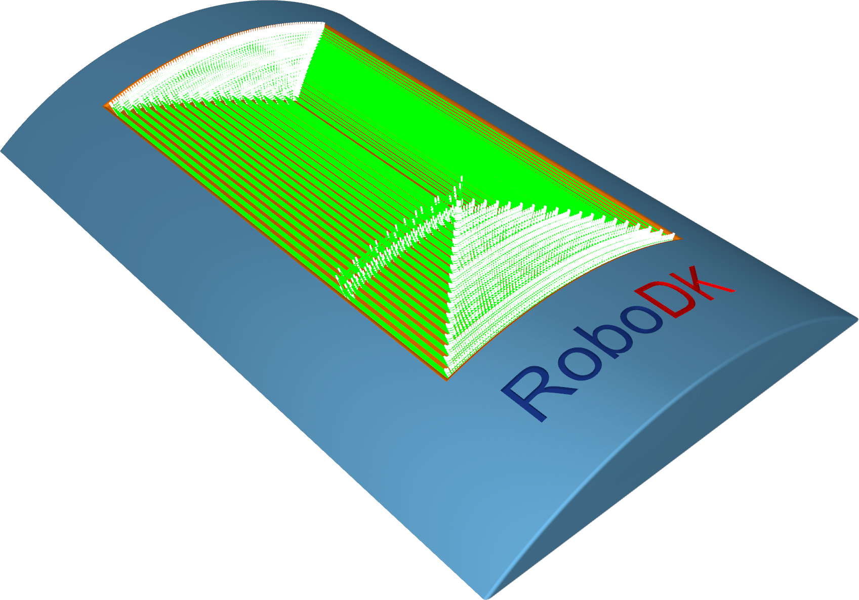
Surfaces–Flowline
The Flowline creates a toolpath that is aligned (or mapped) to the short or long side or along the parametric dimensions (U or V) of the given surface.
The main benefit is that the flowline toolpath can be created without selecting additional bounding geometries like wall surfaces or edge curves. The maximum step-over can be maintained with a constant distance, even if the surface topology is very complex. Also, calculation time is very fast.
Station: CAM-Surfaces-Flowline.
Surfaces–Morph between two curves
This option creates a morph toolpath between two leading curves, input as 'First' and 'Second'. Morph means that the generated toolpath gradually interpolates between the two curves and spreads evenly over the surface.
This option is well-suited for machining steep areas when making molds.
Station: CAM-Surfaces-MorphBetween2Curves.
Surfaces–Morph between two surfaces
This option will create a morph toolpath on the drive surface. The drive surface is enclosed by two check surfaces. Morph means that the generated toolpath is approximated between the check surfaces and evenly spread over the drive surface. Especially the impeller machining with its twisted turbine blades can be machined using this option.
Bi-Tangency - the main advantage is the possibility to compensate the tool to the drive surface and check the surface in the left and right corner of the work piece. All you need to do is to enable the tool radius from (margin) options, which is the distance between the tool center and the surfaces.
Station: CAM-Surfaces-MorphBetween2Surfaces.
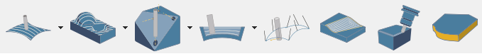
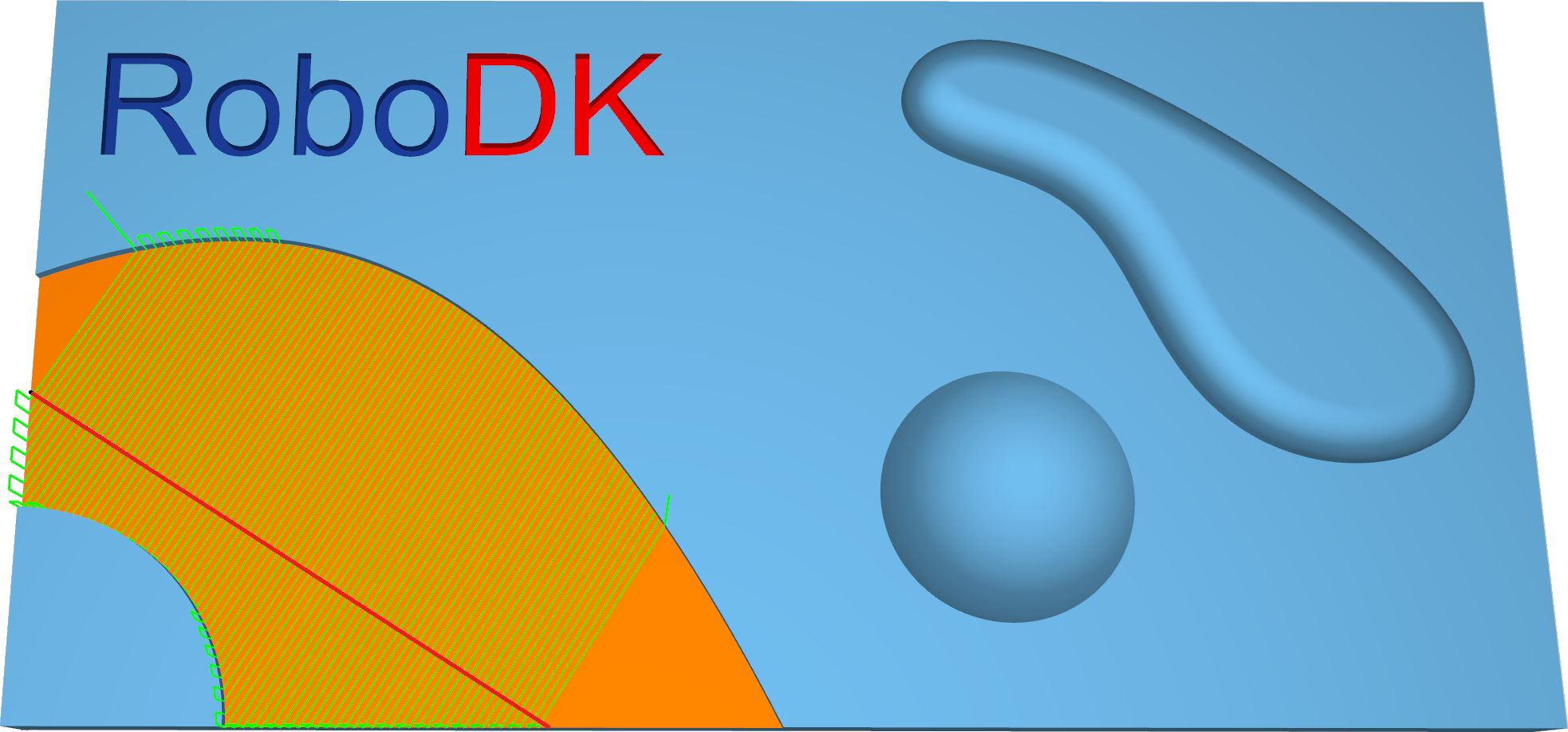
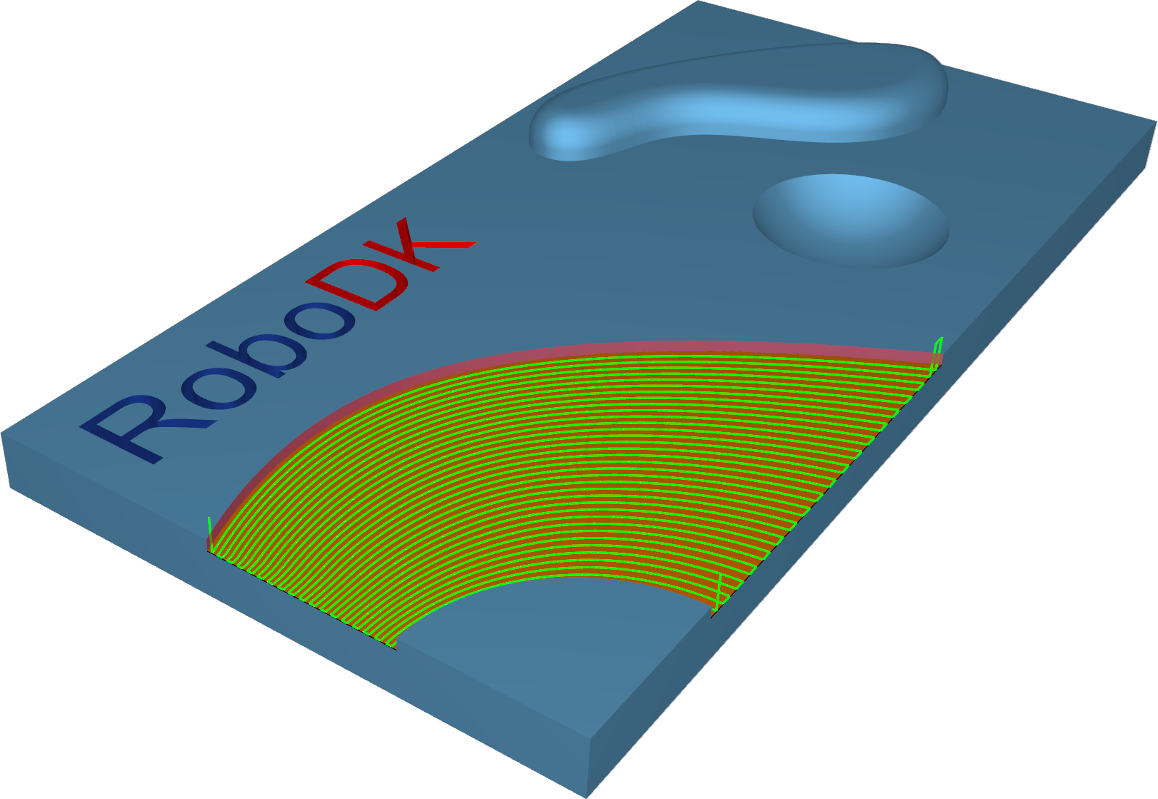
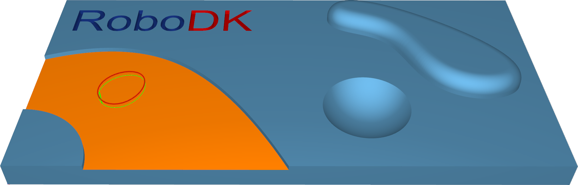
Surfaces–Parallel to multiple curves
The Parallel to curve option will create toolpath segments parallel to the leading curve. The neighboring toolpath segments are parallel to each other. The important point here is that the cuts won't be simply copied next to each other. Every new cut will be an offset of the previous cut.
Important notes:
1.The curve must be located exactly on the surface edge. So, the best curve would be the edge itself. This is very important for toolpath generation. If you don't have a proper leading curve aligned to edge, a wrong toolpath can be generated.
2.For independent curves on the same surface, only the first curve will be used. For more complex models, it means that it is difficult to provide the right leading curve to machine the whole model.
3.For consecutive curves on the same surface, all curves must be joined in a single curve. This step can be performed from any CAD system, or it can be made automatically by the system.
4.For independent curves on the same surface, only the first curve will be used. For more complex models, it means that it is difficult to provide the right leading curve to machine the whole model.
5.Multiple curves selected on independent surfaces will generate different cuts on each surface.
6.The distance between two neighboring toolpath segments is the maximum step-over.
7.You can define a margin to get the exact position where the tool is located at the edge with a certain distance.
8.With the pattern Parallel to multiple curves, it is possible to use multiple curves for multiple surfaces. Each curve will now be used only for the nearest surface.
Station: CAM-Surfaces-Parlallel2MultipleCurves.
Surfaces–Parallel to surface
Parallel to surface will create cuts on your drive surface that are parallel to a leading surface.
Station: CAM-Surfaces-Parallel2Surface.
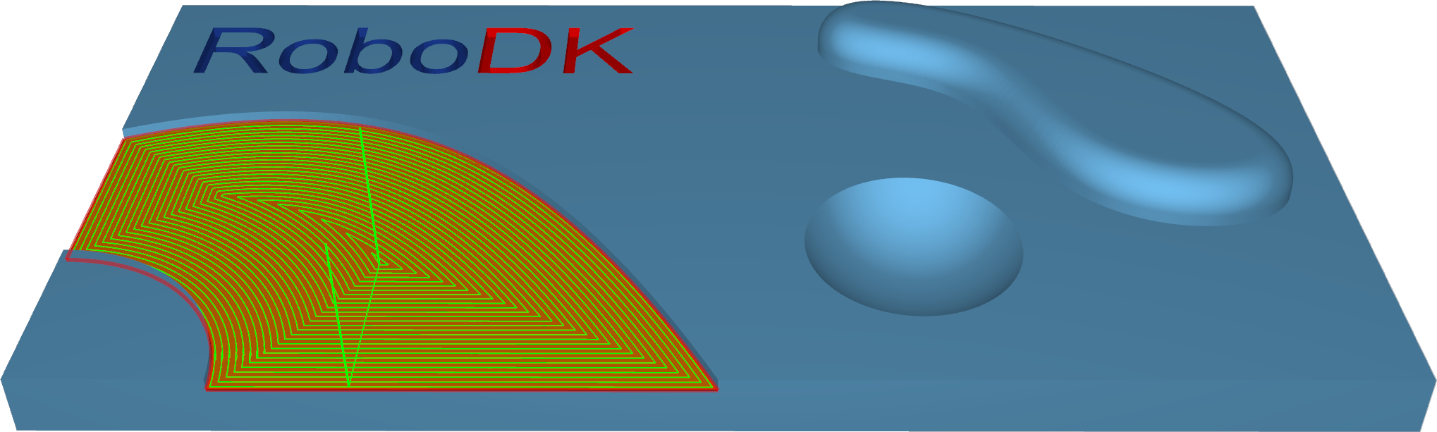
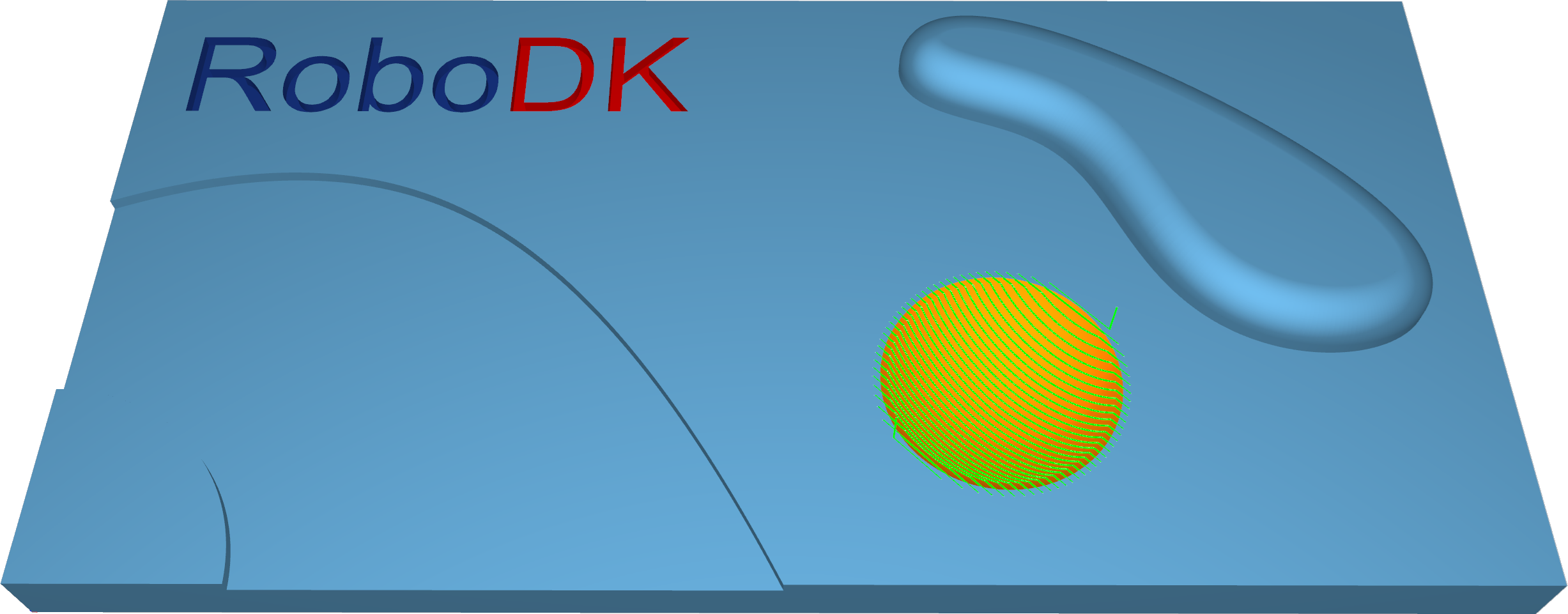
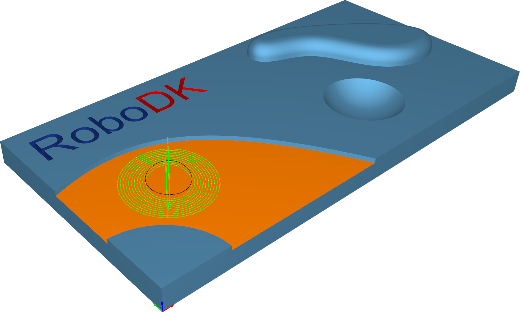
Surfaces–Project curve
With this pattern, either a user-defined curve or a generic pattern can be created. There are 2 2D pattern projections, radial and spiral, and 2 3D curve projections: offset and user-defined.
Station: CAM-Surfaces-ProjectCurve.
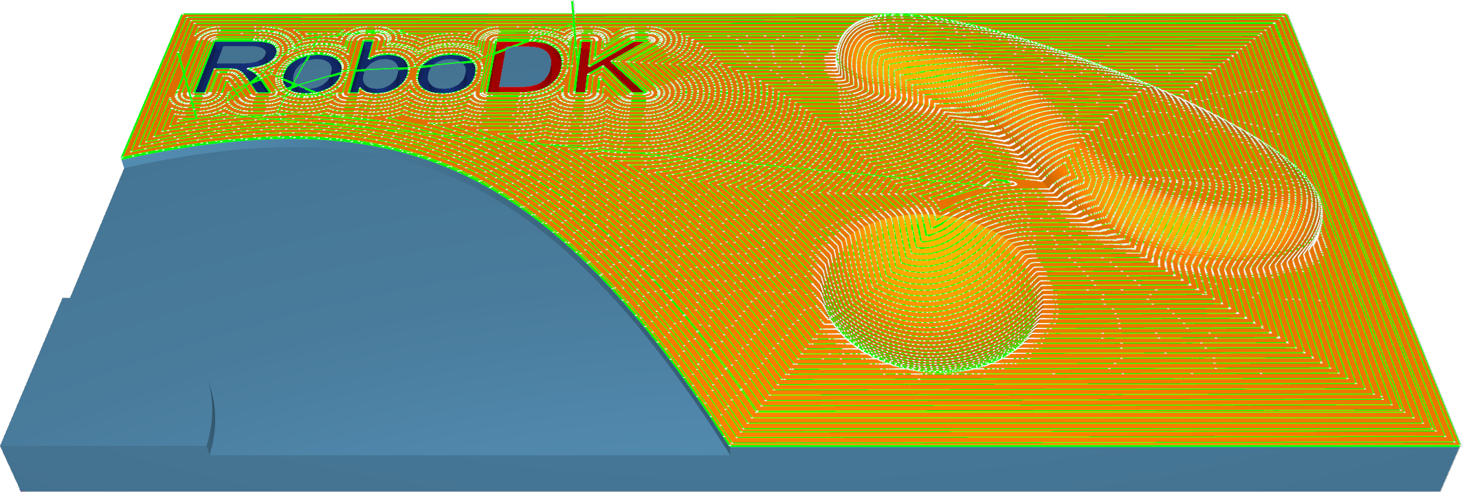
Trimesh–Rough
Roughing is the first stage of machining. This strategy is used to remove large volumes of excess material very quickly and leave a small amount of stock for semi-finishing and finishing strategies. You can use this strategy to create a rough component from a rectangular or core-shaped block.
Toolpath cuts material in successive Z-levels, working from top to down. The 'Depth step' parameter defines the distance between two Z levels. Toolpath is created from model slices and offset outwards. The distance between two offsets is defined by step-over. The toolpath segments are trimmed to block limits. The result is a rough component with a staircase effect over the whole component, which differs from the finished component by a thickness whose value is defined in the offset field.
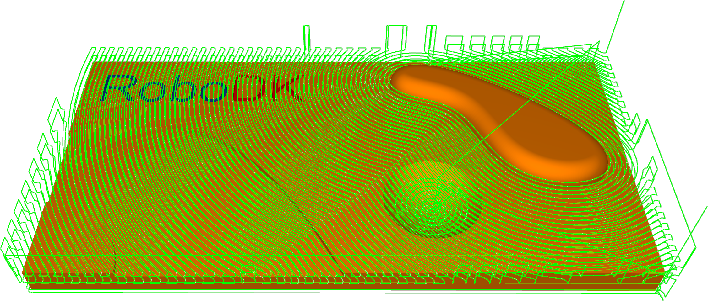
Station: CAM-Trimesh-Rough.
Trimesh–Parallel cuts
This strategy allows the machining of 3d components with toolpath passes that are parallel to each other relative to axes X and Y. Any desired angle in the XY plane can be set using the 'Machining angle in X,Y' parameter.
This strategy is generally used to semi-finish or finish a component. It is best suited to shallow machine areas.
Station: CAM-Trimesh-ParallelCuts.
Trimesh–Project curve
In the Project curve strategy, a 2d or 3d curve pattern is projected on the triangle mesh to create a toolpath.
Station: CAM-Trimesh-ProjectCurve.
Trimesh–Constant Z
This strategy allows the machining of 3d components with toolpath passes that are parallel to a plane that depends on the machining direction. Imagine a component being sliced from top to bottom.
This strategy is generally used to semi-finish or finish a component. It is best suited to machine steep areas - vertical or near vertical walls of a 3d component.
1.Constant Z + Constant Cusp: This pattern enables you to machine parts consisting of steep and shallow regions in one iteration. Steep regions are machined with the help of Constant Z slices. A constant cusp is applied for shallow area processing.
2.Constant Z + Parallel Cuts: This pattern makes it possible to machine parts consisting of steep and shallow regions in one iteration. Steep regions are machined with the help of Constant Z slices. Parallel cuts are applied for shallow area processing.
Station: CAM-Trimesh-ConstantZ.
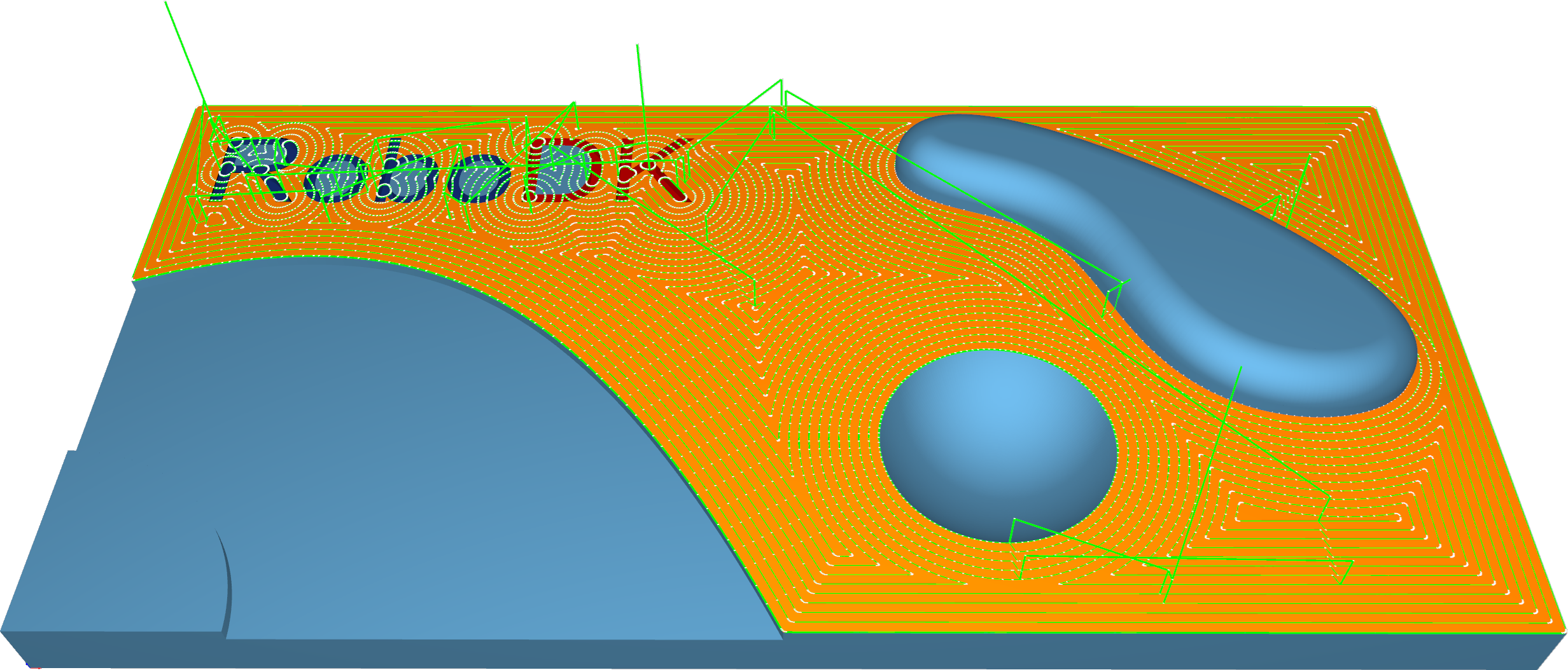
Trimesh–Constant Cusp
This strategy will create an equidistant cut pattern on the machining surfaces. The aim is to have a constant distance between each contour so that the cusps created will have the same height.
This strategy is generally used to semi-finish or finish a component. It is best suited to machine steep as well as shallow areas.
Station: CAM-Trimesh-ConstantCusp.
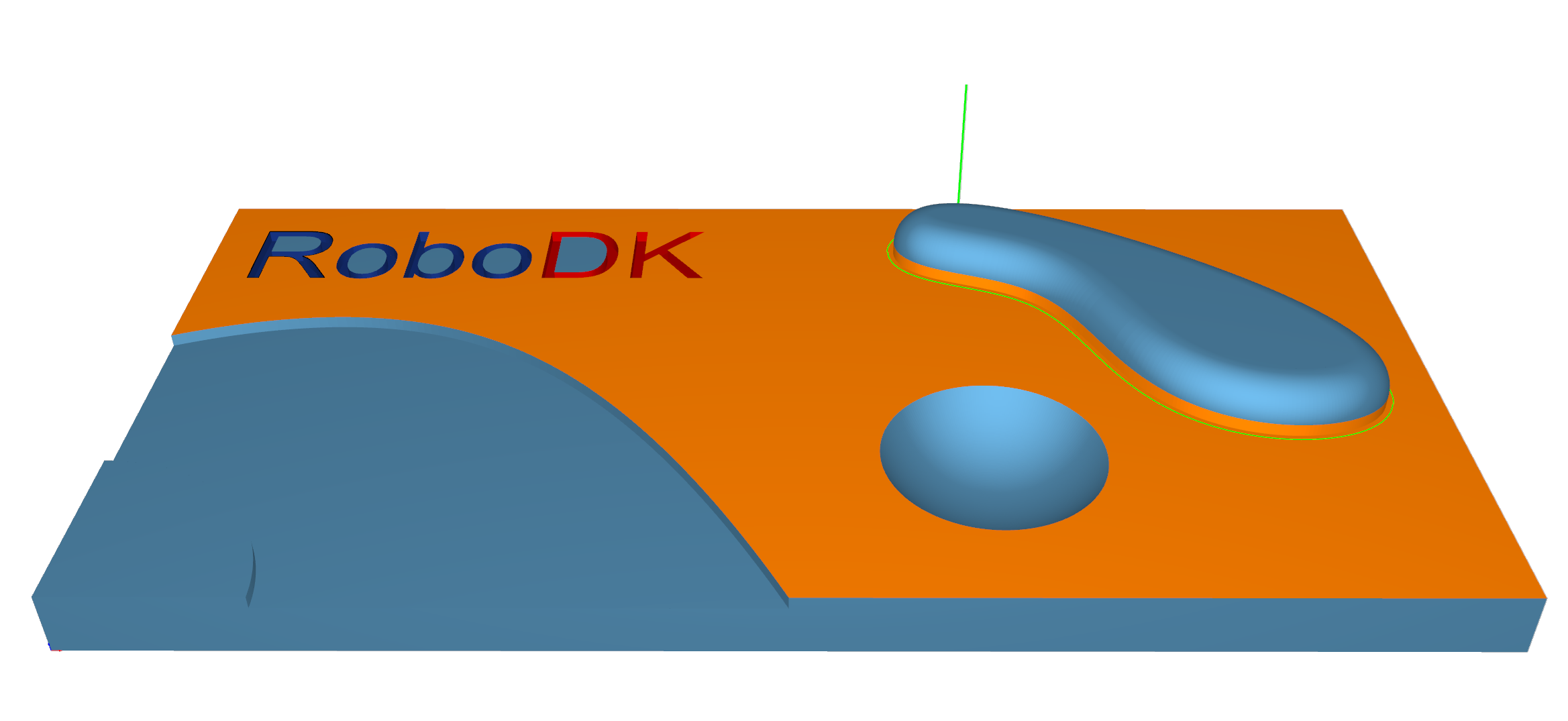
Trimesh–Flatlands
This strategy is designed to machine true flat areas of 3d components with toolpath passes that are offset segments of the flat area boundary. It is generally used to finish a component. It is best suited to machine large flat areas at multiple Z levels.
Flat areas like parting surfaces can be machined by an endmill or bullnose mill cutter using flatlands machining strategy.
Station: CAM-Trimesh-Flatlands.
Trimesh–Pencil
This strategy is intended to provide fast corners and fillets processing. It can be performed via single- or multi-pencil cuts.
Station: CAM-Trimesh-Pencil.
Trimesh–Trochoidal
The strategy provides sequential part contour machining by trochoidal movements.
Could be applied for cutting out part from the stock material.
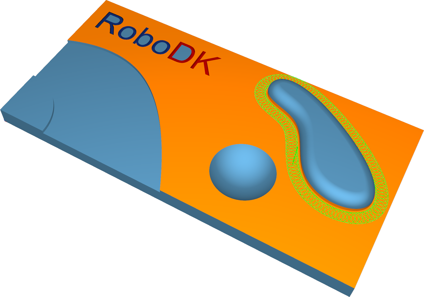
Station: CAM-Trimesh-Trochoidal.
Wireframe–5-Axis Profiling
This calculation provides toolpath generation based on wireframe input drive curves. It works without any machining surfaces.
The tool orientation is defined by tilt lines and is perpendicular to the orientation lines. Tilting settings are required, which can be controlled by the tilting options. The tool axis orientations are interpolated between the lines.
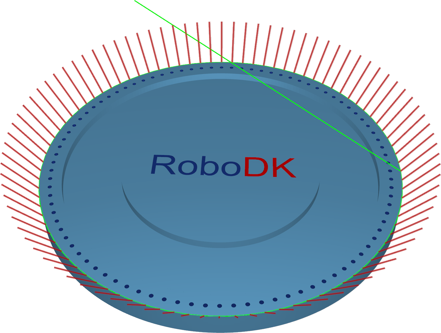
Station: CAM-Wireframe-5ax.
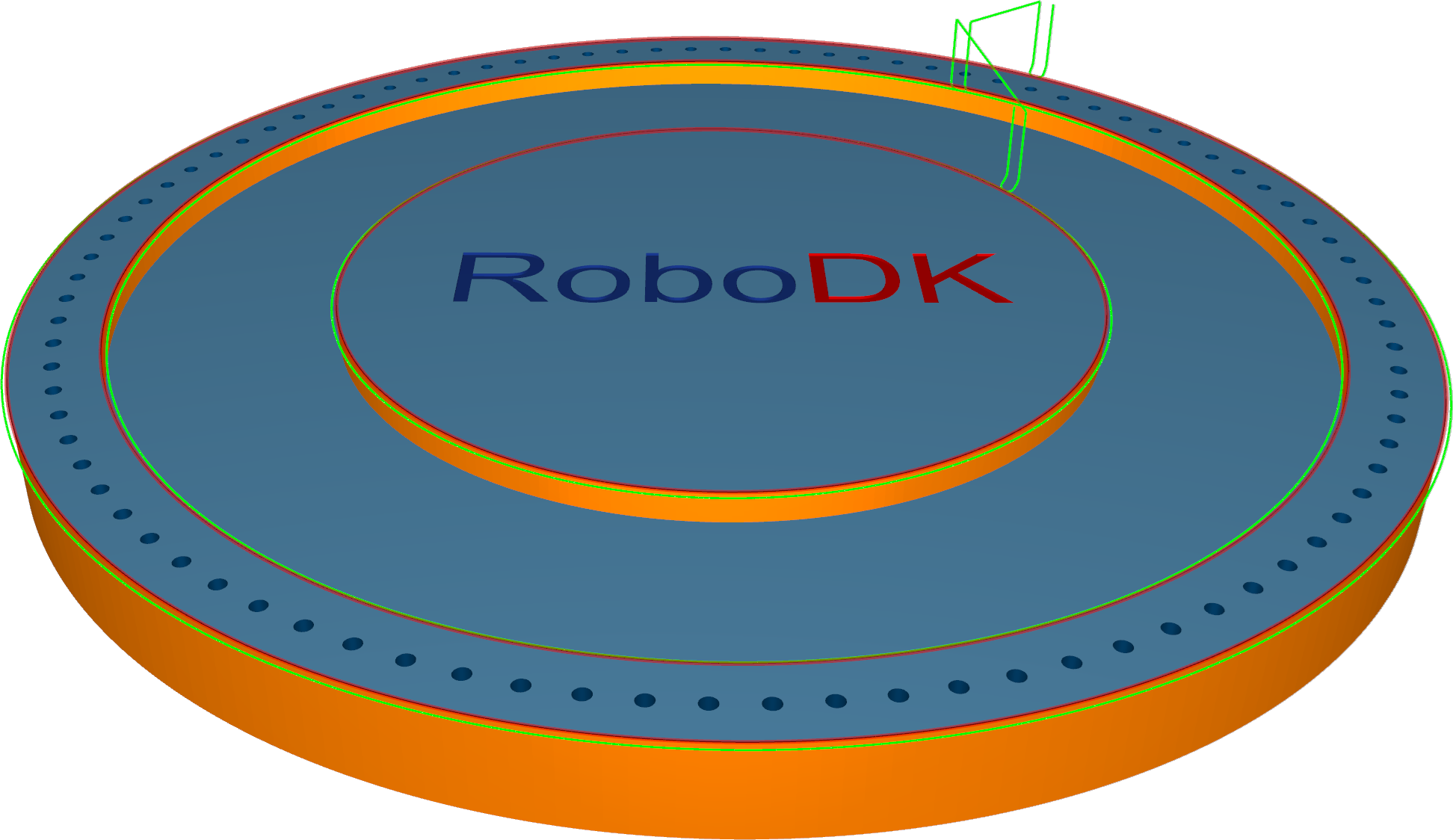
Contouring
Contouring is a highly automated algorithm to create the edge trimming toolpath.
The Contouring calculation strategy is designed for the edge trimming of thin materials. The position of the tool relative to the geometry can be defined by various options, from only a 3-axis output to a more complex 5-axis output with different tool axis orientation options. A key feature of this algorithm is the axial shift where the tool can be engaged with a certain value into the material. The contour can be automated or user-defined.
Station: CAM-Contouring.
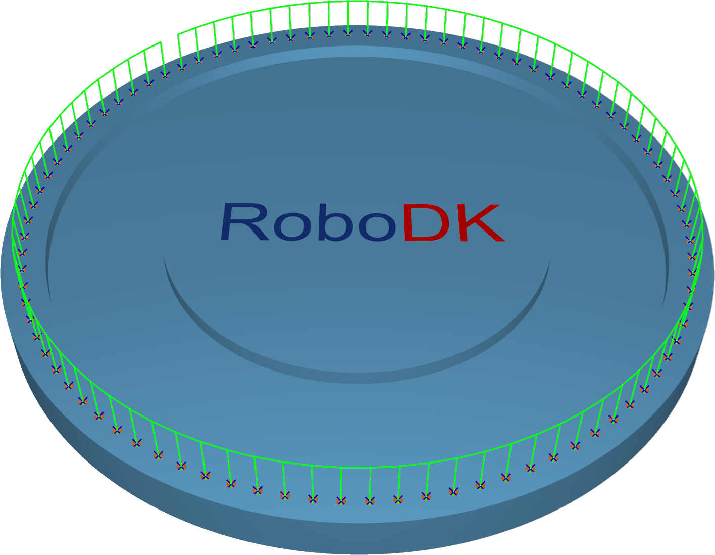
Deburring
The Deburring algorithm creates a deburring toolpath on the outer edges of a part geometry. By default, the orientation of spherical tools relative to the edge is the bi-vector between the two surfaces of that edge. Special tilt settings and other tools adjust the orientation as required.
To detect all the edges, the geometry input (a mesh) must be of good quality.
Station: CAM-Deburring.
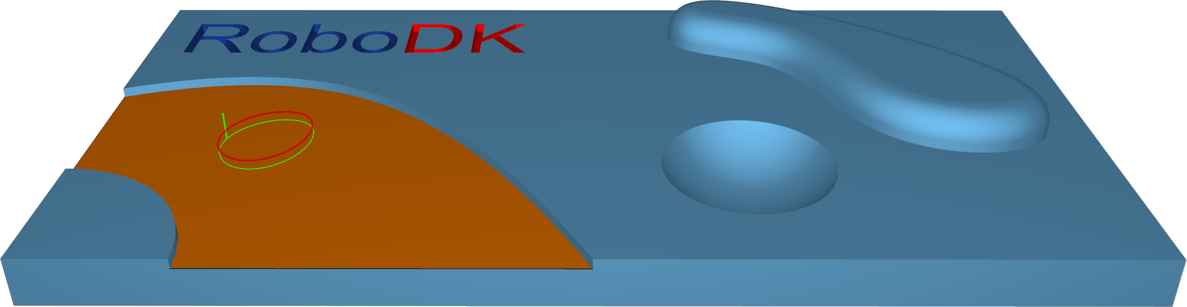
Drilling
The calculation based on drilling points is a very basic drill cycle. It works without any machining surfaces. Drill positions and orientations will be defined either with points or lines.
On surface - with points/lines on the surface, the user must select points/lines that are positioned directly on the surface. The orientation of the tool axis is determined by the surface normal.
Points - For this cycle, the user must select points from the geometry. The drill cycle starts at the selected points. The orientation must be set up on the Tool axis control tab.
Lines - For this cycle, the user must select lines from the geometry. The lines define the position and orientation of the tool as well as the drill depth.
Station: CAM-Drilling-Points.
Geodesic
Geodesic is a generalization of the concept of a "straight line" mapped onto "curved spaces". Those geodesic distances are used to create patterns that consider the distances on the surface topology.
Geodesic machining provides two modes:
1.The contact point mode supports all tools. The output is similar to the surface-based pattern and does not guarantee a collision-free pattern with the surrounding geometry (e.g., in inner corners).
2.The tool center mode supports ball tools only. The calculation is generated in offset space to avoid collisions with the surrounding geometry.
Station: CAM-Geodesic.
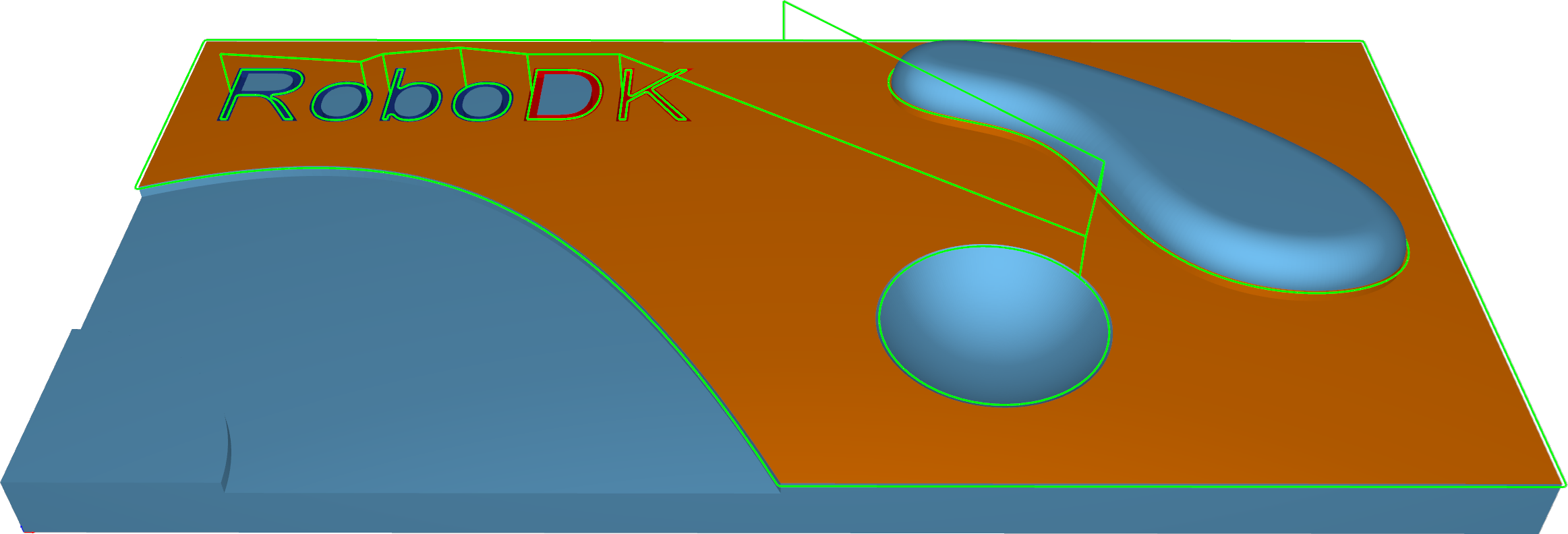
Multiaxis
The multiaxis algorithm creates a multiaxis toolpath that can be used to machine pocket-shaped geometries. The calculation uses STL meshes and IGES geometries as input. The user must specify the floor, wall, and ceiling surfaces, and the system then automatically creates the toolpath.
The Multiaxis Roughing algorithm creates a multiaxis toolpath that can be used to rough out pocket-shaped geometries. The parameters are identical to the triangle, mesh-based roughing cycle, which includes the adaptive roughing feature.
The Multiaxis Floor Finish algorithm creates a multiaxis toolpath for finishing pocket-shaped geometries. Users must specify the part and floor surfaces.
The Multiaxis Wall Finish algorithm creates a multiaxis toolpath that can be used to finish pocket-shaped geometries. The user must specify the floor and wall.
The Multiaxis Rest Finish algorithm creates a multiaxis toolpath for rest finishing pocket-shaped geometries. The user must provide the floor and wall finishing operations as input. The calculation uses containment curves around the unmachined areas, either provided by the user or automatically derived from previous multiaxis machining operations.
The user can choose which areas to machine, and which curves to use as guide curves by selecting one of the following options:
1.Medial axis: The medial axis is used as the drive curve. The main part of the medial axis is calculated from the containment curves.
2.Floor boundary: The boundary of the floor surface is used as the guide curve.
3.Do not machine: Do not machine this area.
Station: CAM-Multiaxis-Roughing.