3-Axis Mold Robot Machining
To start the project, you will first have to select RoboDK’s 3-axis mold machining example in the default library.
RoboDK settings
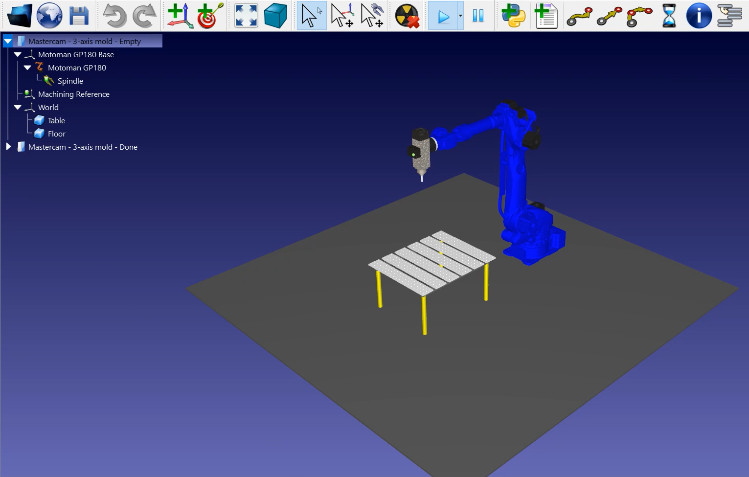
This example uses the Motoman GP180 robot, a cutting tool mounted on a spindle and a table to hold the part in place.
Load the station:
1.Select File➔ 
2.Locate the 3-axis mold machining example fromRoboDK’s examples section:
C:/RoboDK/Examples/ Plugin-Mastercam-3-Axis-Mold-Machining.rdk.
Now that you have loaded the station you can open Mastercam and load the project from C:/RoboDK/Other/Plugin-Mastercam/Examples/Mold.mcam.
Machining toolpath in Mastercam
Open your 3D object in Mastercam and launch the cutting simulation. In this example, the 3D object is a mold metal piece with an already created cutting path using Mastercam tools.
To simplify this example, the number of passes required to machine that part has been greatly reduced. In reality, you would have a lot more lines or cutting path in the mold that you wouldn’t be able to really see the tool in action.
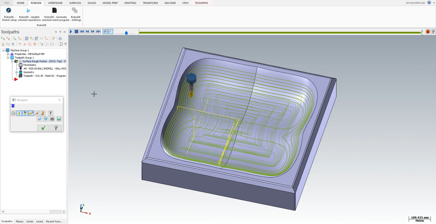
The Mastercam cutting simulation shows you every movement the tool needs to do during the program.
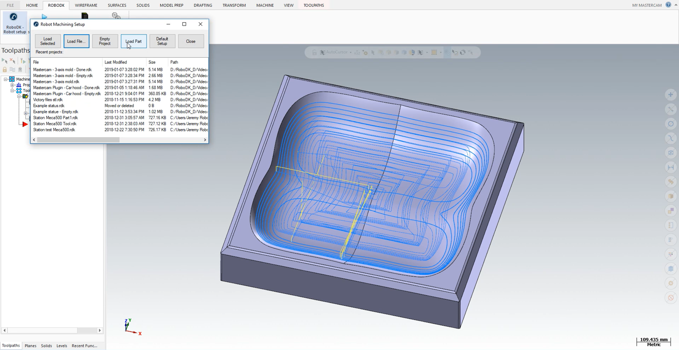
Follow the next steps to load your part into RoboDK:
1.Select the RoboDK tab and select RoboDK – Robot setup.
2.Select Load Part.
You should see the part loaded on the active reference frame (Machining Reference) on the table of the RoboDK station.
The next step is to import the cutting path from Mastercam to RoboDK.
1.Select the RoboDK tab in Mastercam.
2.Select RoboDK – Update selected operations.
3.Go to RoboDK.
Robot Machining in RoboDK
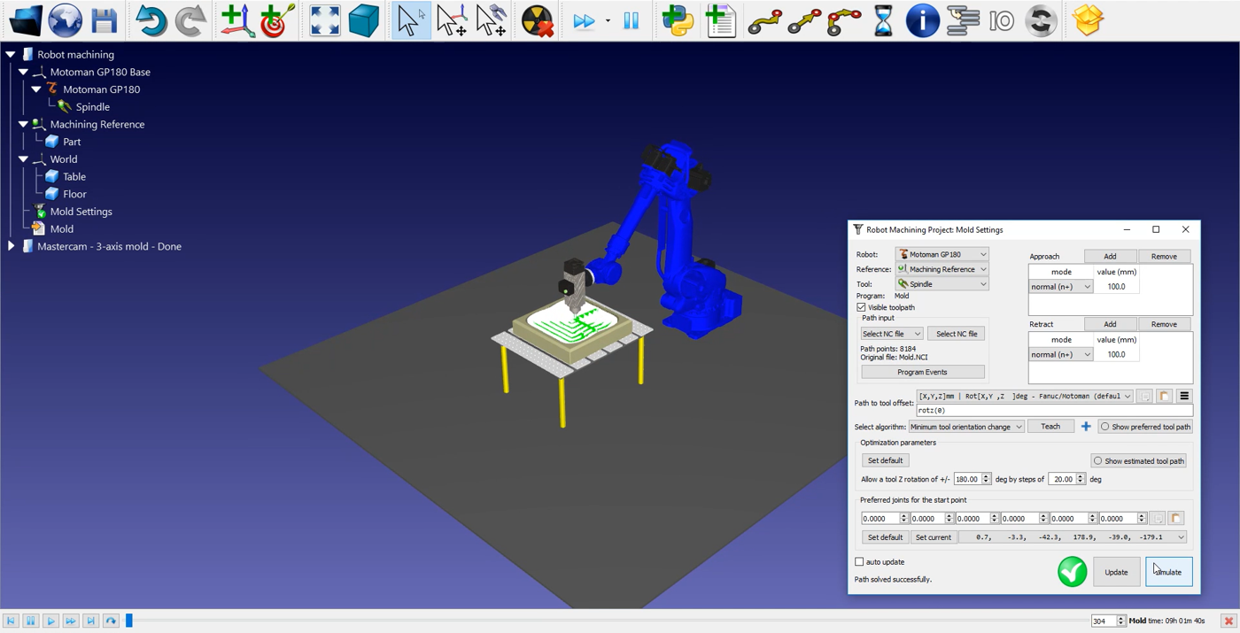
Once the robot machining path has been imported in RoboDK you should see the robot machining toolpath attached to the mold reference of your RoboDK station.In 
You can also adjust the value of the approach and retract movements before and after the cutting path. A 100 mm should be fine in this example. If there is a risk of collisions, you can increase those as much as you want inside the robot working range.
The next step is to verify if the order in which the path sections will be executed is correct by selecting

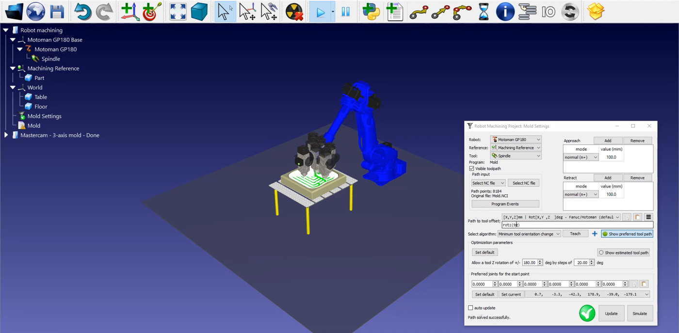
Follow these steps to adjust the tool orientation:
1.Double click on the
2.Select Show preferred tool path. Some ghost tools will appear as shown in the image below. Those represent the position of your tool along the path.
3.Modify the rotz (0) value by scrolling your wheel up until 90 degrees. You will see the rotz value changing and the ghost tolls position changing with it.
4.Select Update ➔ Simulate.
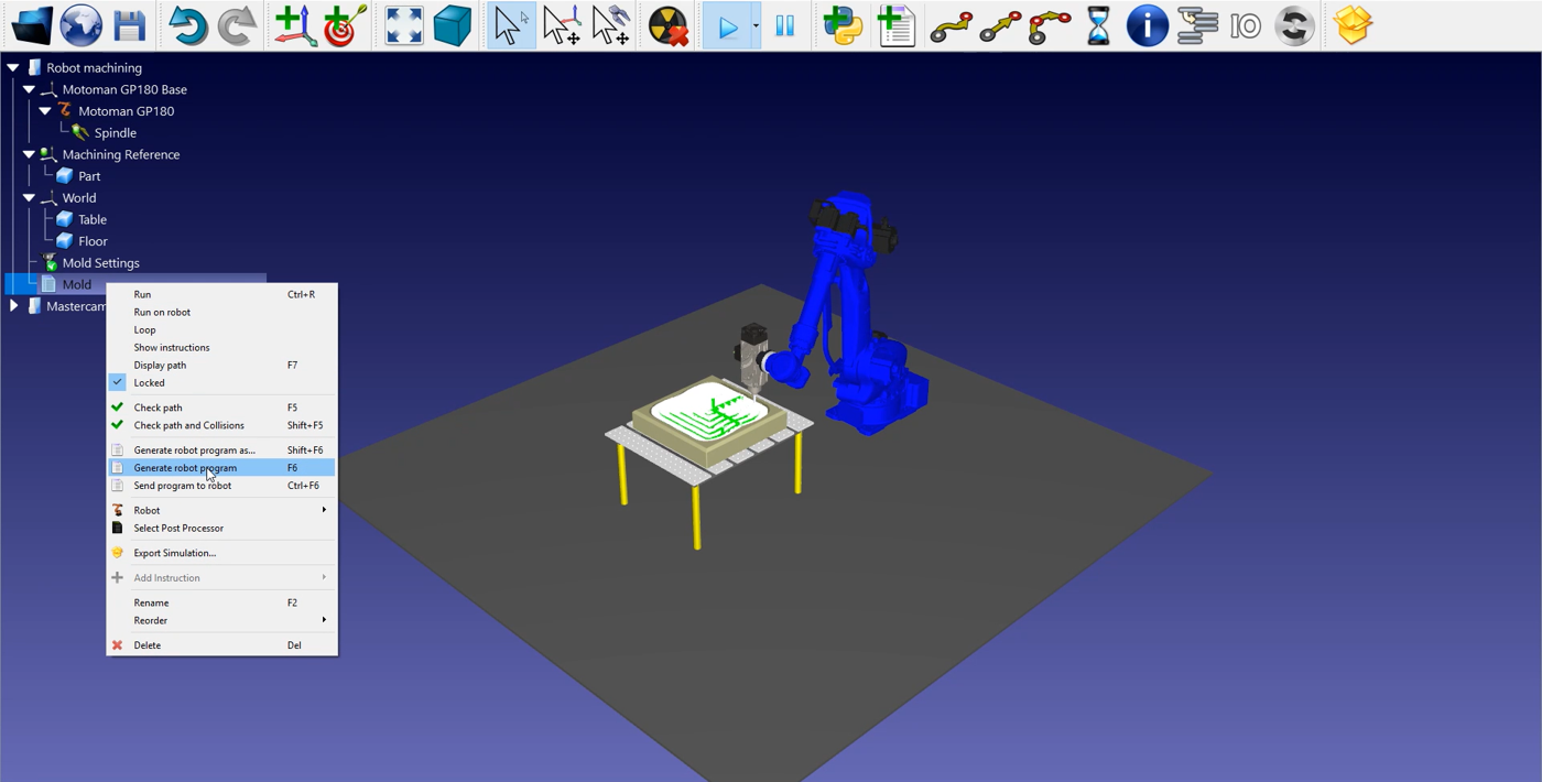
To generate your robot program, make sure to use the right post processor. Double click on the 
Finally, right click on 
The Motoman JBI file is now ready to be transferred to your robot controller.