Robot Cutting
Introduction
This example will show you how you can use RoboDK for 5-axis robot machining using the Mastercam plugin. In this example the goal is to trim the excess material around a car hood using a Fanuc robot with a cutting tool mounted on a spindle.
With the RoboDK plug-in for Mastercam you can quickly set up robot machining projects direclty from Mastercam to RoboDK. This plug-in allows you to program more than 50 different robot manufacturers and 500 robots.
The RoboDK plug-in for Mastercam supports NCI (native preprocessed Mastercam files) and standard APT CLS and G-code files. The plug-in is free if you have purchased a RoboDK license.
5-Axis robot cutting
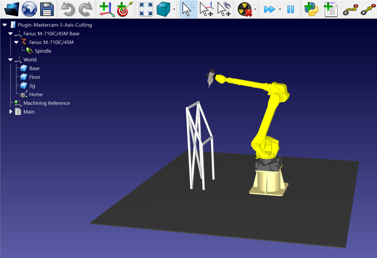
To start the project, you should select RoboDK’s 5-axis cutting example in the default library.
RoboDK settings
This example uses the Fanuc M-710iC/45M robot, a cutting tool mounted on a spindle and a jig to hold the the car hood.
Load the station:
1.Select File➔ 
2.Locate the 5-axis cutting example fromRoboDK’s examples section:
C:/RoboDK/Examples/ Plugin-Mastercam-5-Axis-Cutting.rdk.
Now that you have loaded the station you can open Mastercam and load the project C:/RoboDK/Other/Plugin-Mastercam/Examples/Car hood.mcam.
Cutting toolpath in Mastercam
Open your 3D object in Mastercam and launch the cutting simulation. You can see that the software adjusted the orientation of the tool to match the cutting surface.
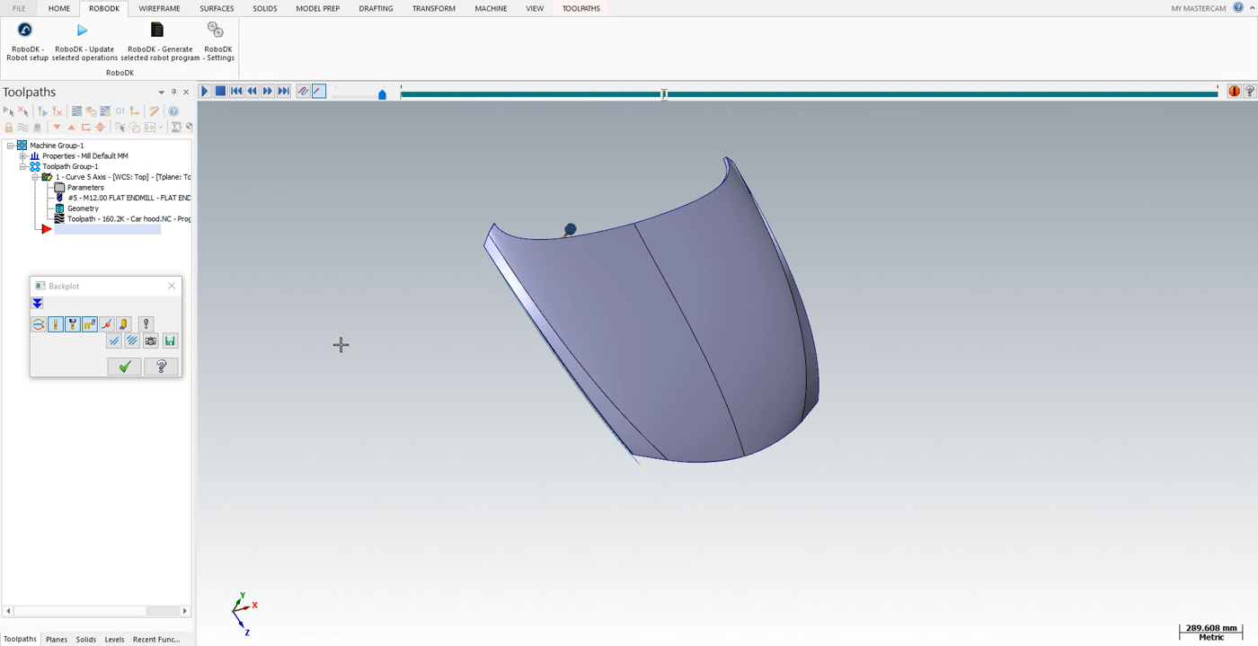
Follow the next steps to load your part into RoboDK:
1.Select the RoboDK tab and select RoboDK – Robot setup.
2.Select Load Part.
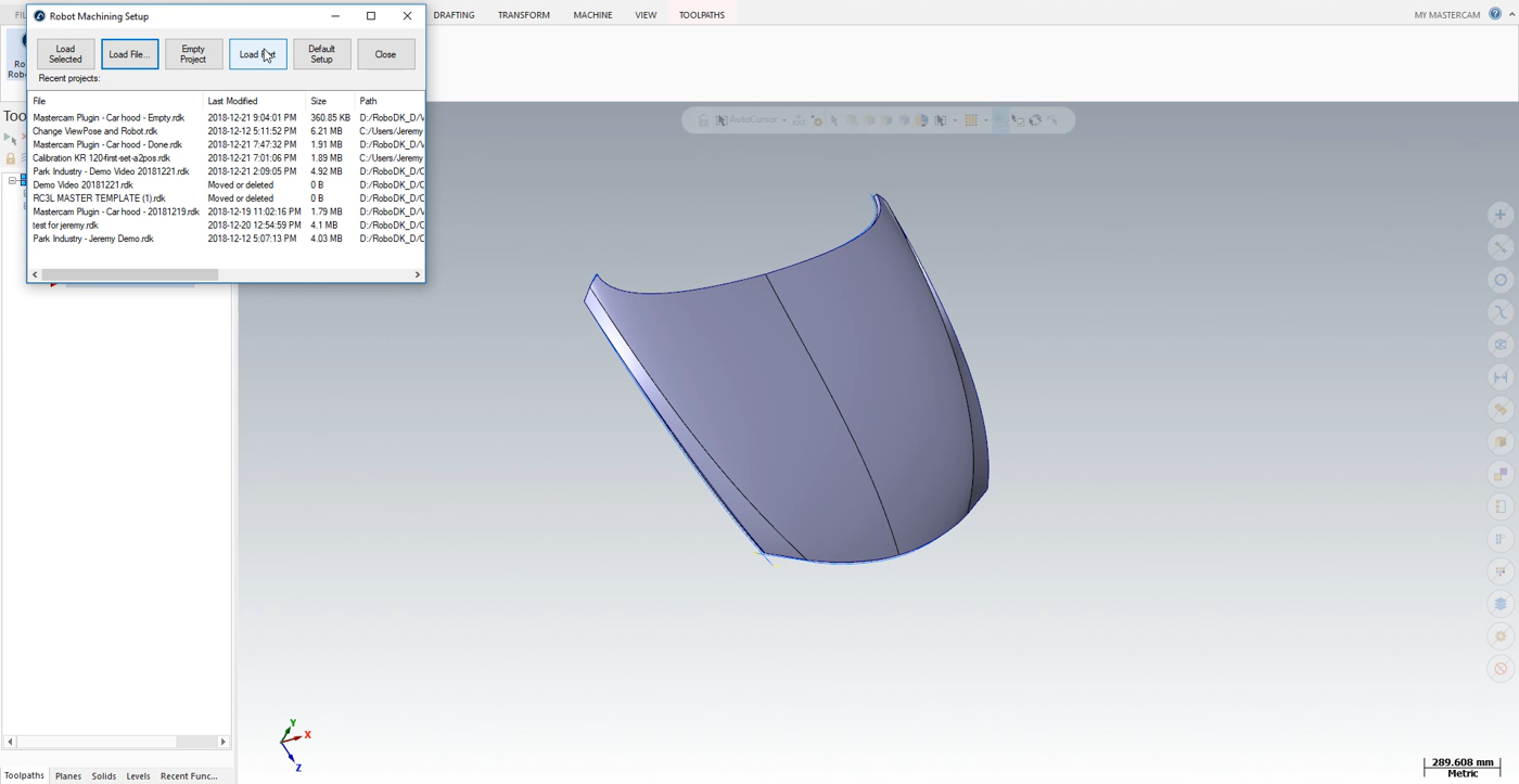
You should see the part loaded on the active reference frame (Machining Reference) on the jig of the RoboDK station.
The next step is to import the cutting path from Mastercam to RoboDK.
1.Select the RoboDK tab in Mastercam.
2.Select RoboDK – Update selected operations.
3.Go to RoboDK.
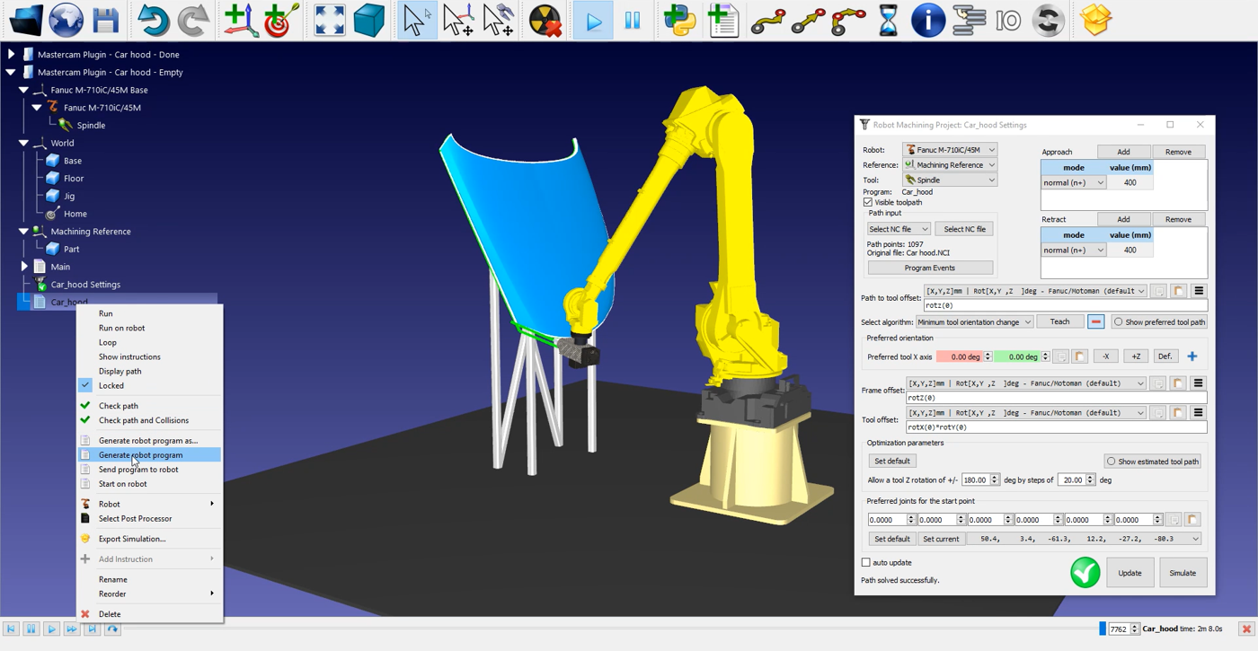
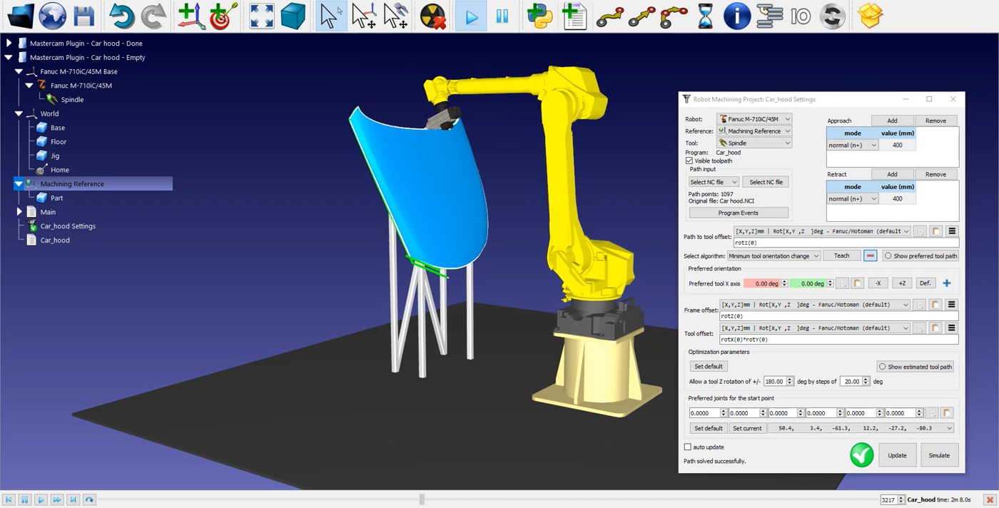
Robot cutting in RoboDK
Once the robot cutting path has been imported in RoboDK you should see the cutting toolpath attached to the mold reference of your RoboDK station. In the 
You can also adjust the value of the approach and retract movements before and after the cutting path. A 400 mm approach/retract should be safe this example. Those movements are now 4 times longer than the default approach/retract and will help avoiding any collision with the part.
You can also adjust the orientation of the part in the lower section of the menu.
The next step is to verify if the order in which the path sections will be executed is correct by selecting

To generate your robot program, make sure to use the right post processor. Double click on the 
Finally, right click on 
The Fanuc LS and/or TP files are now ready to be transferred to your robot controller.