2D sketch from Fusion 360
Open your object in Fusion 360. In this example the object is a plastic part. The goal of this project is to remove excess material in the three holes, and all around the part near the bottom of it.
First, you need to make sure that you are in the “Manufacturing” workspace tab of Fusion. We should follow these steps to create the tool path:
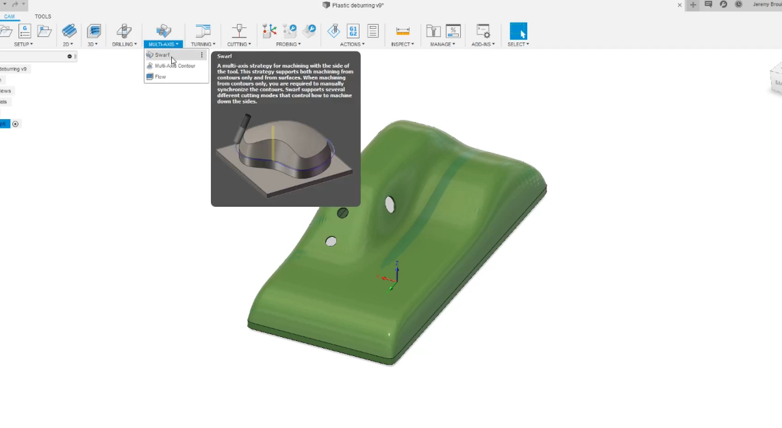
1.Select Multi-Axis and then select the Swarf tool.
2.Select the tool you wish to use (in this example we will be using a custom tool from our RoboDK station) and then select the hole to create the first path.
3.To get the tool path on the right side of the surface, we will select Machine Other Side and then select Ok. Follow this procedure for each hole.
4.To do the same thing to the bottom part, you will select the Swarf tool and then select the bottom part.
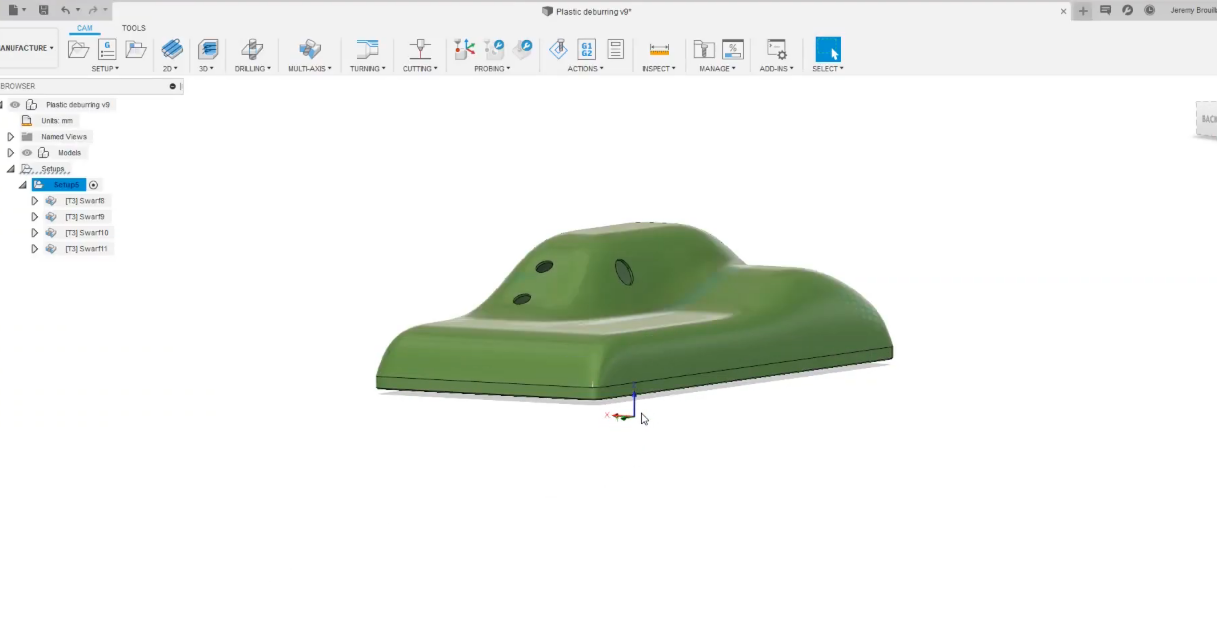
5.Once the calculation is done, we will simulate the paths we just created: Select your Setup and then select Simulate.
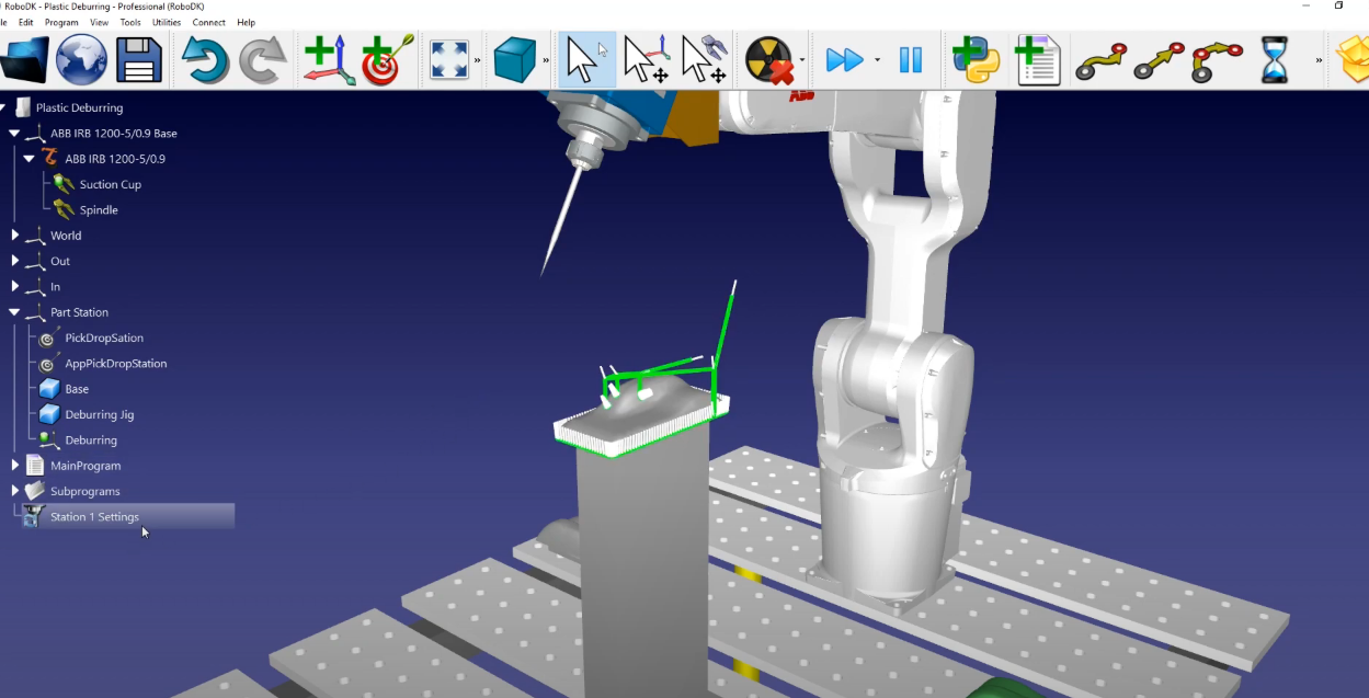
You will have a complete tool path for your robot. We will need to go back into RoboDK to make sure that the “Deburring” reference frame is activated. To do that we must:
Go into RoboDK: select Deburring and then select Activate Reference Frame.
Now that the Deburring reference frame is activated, the program will be exported with respect to that reference frame. e will go back into Fusion 360 and verify that the image is as shown:
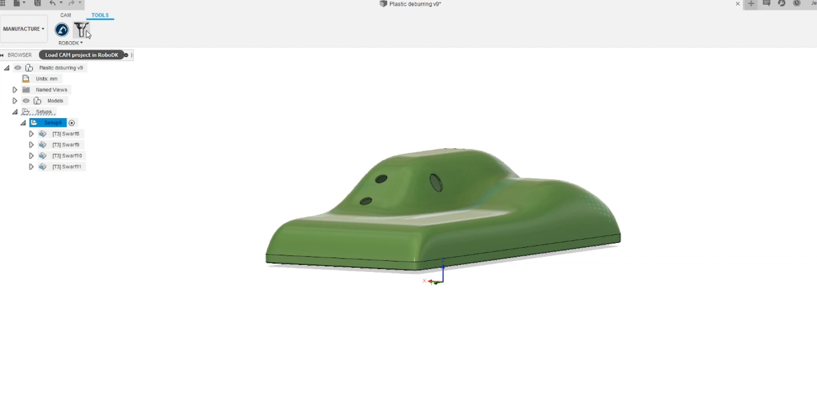
Follow these steps to load your sketch into RoboDK:
1.In Fusion 360, you have the RoboDK plugin. Simply select Load CAM project in RoboDK
2.If we go back to RoboDK, we can find the cutting path at its place. A “Machining Project” called “Plastic Deburring” was created: Select Deburring and then select Visible.
3.We can rename the cutting toolpath to “Station1 Settings”: Right-Click on Plastic Deburring to rename it.