RoboDK station
The next step is to verify if the order in which the path sections will be executed is correct by selecting 
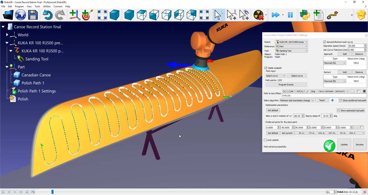
You can see the little white lines coming out of the path on the canoe. Those are the normals to the surface. In this example all seem to have been correctly imported.
Follow these steps to set up the direction of the path:
1.Select
2.Click on Select curve.
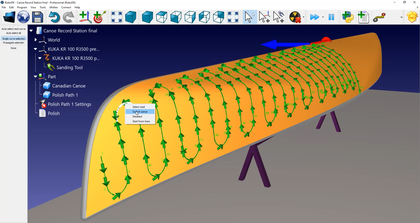
Now you can see the order and direction in which the path segments are executed. If you want to change direction, right click on it, and select Switch sense.
In this case, the path needs to be redone:
1.Right click on an empty space of the station (i.e. blue background).
2.Select Reset selection.
3.Select the line you want to start with. Make sure that it is pointing in the right direction.
4.Select the Auto select all tool on the top left-hand corner of your screen.
5.Select Done.
You can now simulate your station by double clicking on
You can also add normal movements of 200 millimeters to help avoid collision between the robot and the canoe by double clicking on
You can modify the approach and retract speed by selecting
In this menu you can also activate the Set Rounding option. By default, every white line along of your path is a point that will be sent to your robot controller as points were the robot needs to stop. In a polishing or sanding application, this it is not the best behavior.
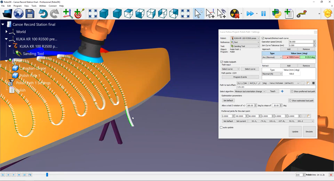
Activate the Set Rounding checkbox to activate the continuous movement option in your controller. Depending on the robot brand the name of that option can be “rounding”, “constant movement” or “zone data”. In this example the value will be 0,5mm.
In this example, since we are using a KUKA robot you’ll obtain an SRC file when you generate the robot program. This file that can be read by a KUKA KRC controller.
Follow these steps to generate a robot program:
1.Right click on 
2.Select OK.
3.Right click on