Robot Welding
Introduction
This example will show you how to use the RoboDK plugin for SolidWorks. This example includes a table and 2 angle irons to show you how you can use RoboDK’s feature to improve your welding paths.
With the RoboDK plug-in for SolidWorks, you can easily program an industrial robot for welding.This example includes a table and 2 angle irons to show you how you can use RoboDK to improve your welding paths.
Robot welding example
To go through this robot welding project, you should first select the RoboDK robot welding example in the default library. Then you should select the welding paths/sketches in SolidWorks. Then you should adjust the robot path in RoboDK.
Setup
You should first import the part and the welding paths from SolidWorks.
Import the project from SolidWorks:
1.Go to the RoboDK tab in SolidWorks and select Auto Setup.
2.Select the welding paths. Make sure to also select the faces as they help orient the robot tool.
3.Now that you have imported the path from SolidWorks, you can go to RoboDK.
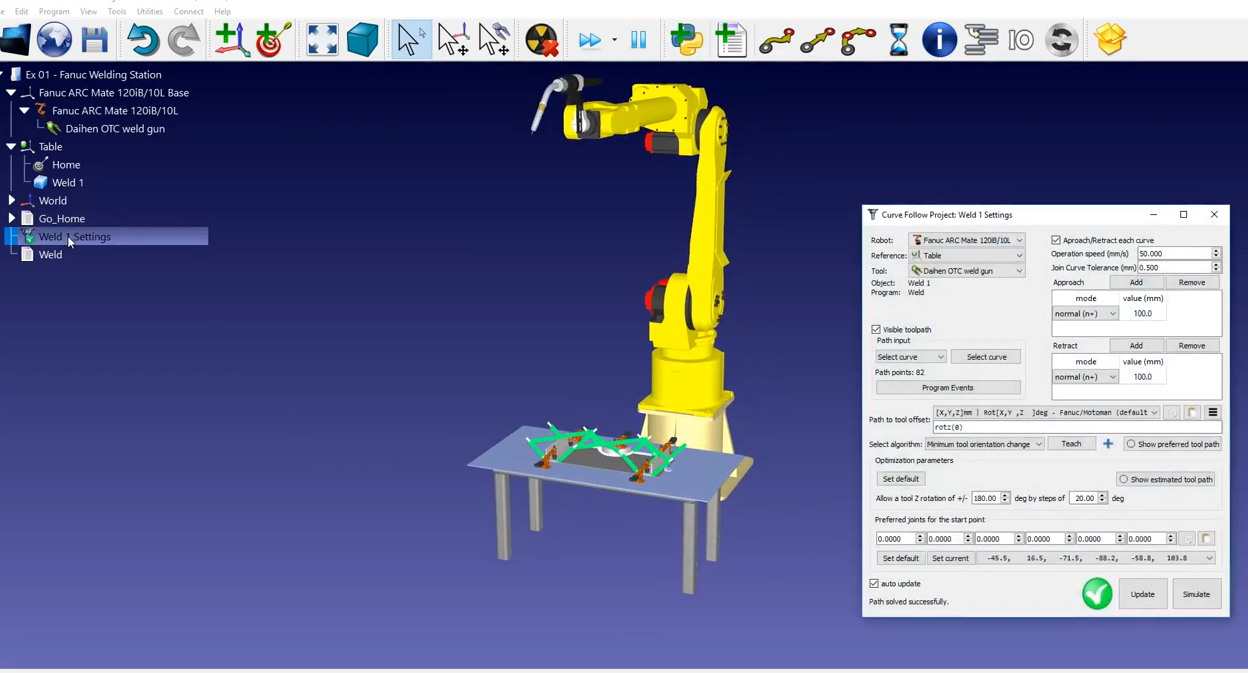
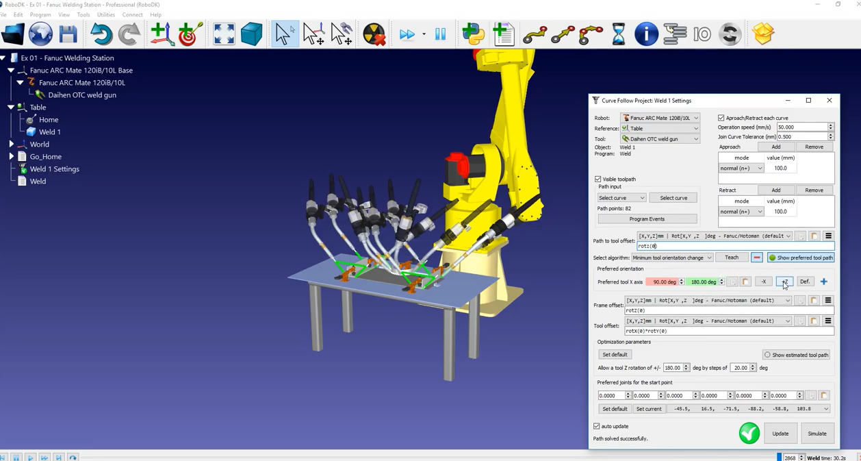
4.In the station tree, click Weld1 Settings which will open the Curve Follow Project.
5.Click Update to generate the program and then Simulate.
2D sketch from SolidWorks
In this section you will learn how to improve or customize the order of motion for each welding curve. The welding gun is following the path as it is supposed to. However, we can see that the orientation is a bit off, and we can see that the path is far from optimal.
First, you should fix the path itself:
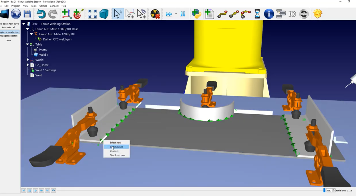
1.In the Curve Follow Project, click on Select Curve (going from 1 to 2, then 3 to 4, 5 to 6, 7 to 8, and 9 to 10).
2. The order from the welding sections makes sense. However, the welding direction does not seem to make sense.
3.To switch the direction of a welding path (such as path 3 to 4), right click the path and select Reverse direction – you can see that the arrows of that path changed direction.
4.You can do the same for path 5 to 6 and path 7 to 8.
5.Once your modifications are done, you can select Done on the right window.
6.Click Update to generate the program and Simulate to start the simulation.
Now that the order of the paths seems to make more sense, you can adjust the orientation of the tool along the path to better improve the robot motion.
7.In the Curve Follow Project menu, click on Show preferred tool path. A variety of ghost tools will appear to show you the orientation of the tool for different positions along the path.
8.The first tool orientation option that you can try is the Path to tool offset around the “Z” axis. To do so, you can manually enter in a value or bring your mouse over it and use the scroll wheel to bring your value up or down.
9.By doing this, you can see the orientation of the ghost tool changing.
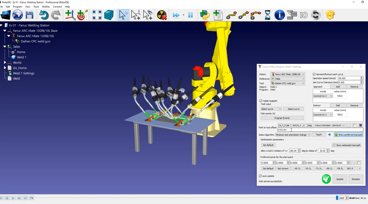
In this case, the basic option does not seem to fix our problem. Fortunately, you can have more options to work with; you can reveal them by clicking the blue plus button and change them according to your project.
10.You can change the rotation around the Z axis (rotz) to its original value, zero, and then click on the “+Z” button.
11.As you can see with the ghost tools, the robot flange will always be on top of the part. Click Update and then Simulate to simulate the result.
12.If you use the scroll bar, the new tool orientation facilitates the cable management of the tool; it has no risk of interfering with the robot.
Approach and retract movements are especially important to avoid collisions between the tool and the part. The Curve Follow Project automatically create an approach and a retract for every welding path. By default, these movements are 100 mm long and are normal to the welding path.
To avoid any collisions, you can modify them to be 200 mm long and keep the same orientation.
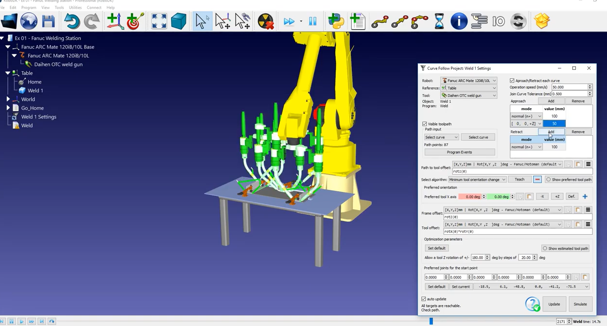
Alternatively, you can add an additional approach movement along the Z axis of the coordinate system:
1.Put back the default normal approach of 100 mm.
2.Add a movement, for example, along Z.
3.Set it to 50 mm.
4.Press Update and Simulate once you are finished.
5.Now the robot retracts normal to the welding path and then straight up.