Align object with reference
This section explains how the reference frame (coordinate system) of an object can be aligned with respect to its own geometry. This section allows moving the reference frame of an object to a location that can be identified in a real setup.
Follow these steps to virtually align the reference frame of an object according to specific points of the object geometry:
1.Load the object
2.Select the active 
3.Select Program➔
Make sure the reference frame is directly attached to the station root (not to other Reference Frames).
4.Right click the reference frame and select 
The procedure is very similar to the previous section. The main difference is that we must select the points of the virtual object instead of the real object.
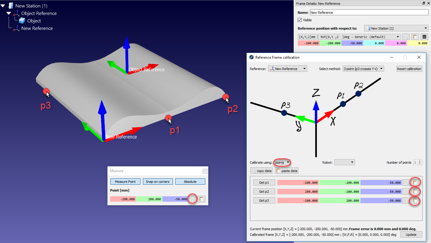
5.Select the desired calibration method.
For example: The 3-point method (with the 3rd point crossing the Y+ axis).
6.Select Calibrate using points
7.Select Tools➔Measure to open the Measurement Tool
8.Select the Absolute button in the Measurement Tool so that the points are measured with respect to the Station (absolute reference)
9.Select the 3 points on the virtual object (one by one) and enter them in the Reference Frame calibration window
10.Select Update. The reference frame should appear at the desired location.
11.Right click the object and select Change support. Then, select the new reference frame. The absolute position of the object will not change. However, the relative position of the object with respect to the new reference frame will be properly defined.
12.The object and its own reference are ready for Offline Programming: Drag and drop the new reference frame to the robot reference frame.