The Reference Frame definition utility described in the previous section provides two ways of calibrating the position of a turntable with respect to a robot. The calibration/identification of the turntable can be done using the robot with a properly defined tool or a measurement system (such as a laser tracker).
We need to retrieve the position of one point in the turntable multiple times as we move the turntable axes. We currently support calibrating 1-axis and 2-axis turntables.
Important: Properly define the TCP before identifying the reference frame (unless you use points measured from an external measurement system). This is important because the Reference Frame is identified using the robot kinematics. This also applies if you retrieve points from the robot teach pendant. Any errors coming for the tool calibration (TCP) will be transferred to the identification of the turntable position.
Calibrate a one-axis Turntable
This section guides you to calibrate a 1-axis turntable. You can calibrate your 1-axis turntable using a well-defined TCP and a static point on the turntable.
Follow this procedure to calibrate your 1-axis turntable.
1.Select Utilities➔ Define Reference
2.Select the Reference Frame to define/calibrate. Alternatively, right-click a Reference Frame and select Define Reference Frame.
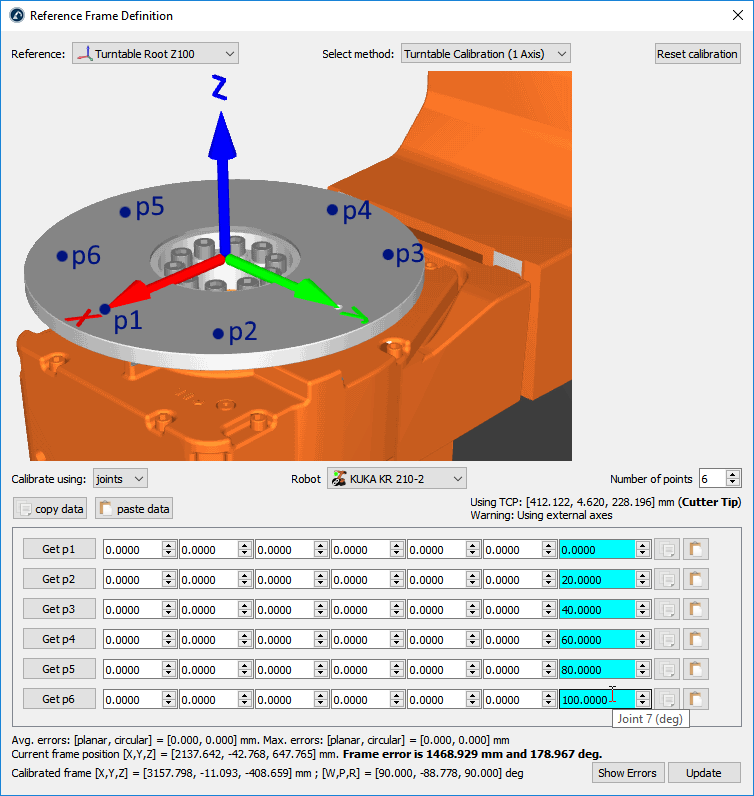
3.Select the method Turntable Calibration (1 Axis)
4.Select Calibrate using joints (default setting). You can change it to points if you have the XYZ position of each point with respect to the robot base frame.
5.Specify the robot if more than one robot is available in the station.
6.Select the number of points you would like to take (the minimum required is 3).
Important: You should probe the same point of the turntable with the robot as you move the turntable. The turntable needs to be moved in the positive sense of rotation (as shown in the previous picture). It is recommended to use a minimum of 6 to 10 points to have a better understanding of the errors involved in moving the turntable.
Important: The first point will define the X axis of the turntable (static reference).
Important: The XY plane of the calibrated reference frame will match the plane described by the arc/circle. You may need to adjust this offset if you didn’t take the points in that plane. For example, you can add a new reference frame nested to the calibrated reference frame to represent the root of the turntable.
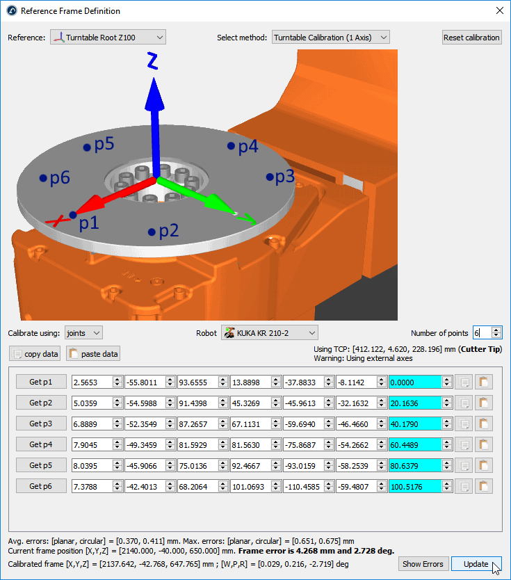
7.Start filling the table with the robot joint positions (or points).
Tip: The list of configurations can be filled manually or by using the copy/paste buttons (buttons at the right of the joint values).
Tip: If you are connected to the robot, you can select the “Get p” buttons to retrieve the robot joints directly from the robot. More information to set it up is available in the Robot Drivers Section. This option is not available for all robot controllers and it may require additional software options sold by the robot manufacturer.
Important: If you enter the values manually it is recommended to provide each joint value with at least 4 decimals (when providing joint values). The allowed number of decimal values can be changed in Tools➔Options➔Accuracy➔Max Decimals.
Note: RoboDK will keep a copy of the provided data in the RDK station once you select update.
8.Finally, select Update to apply the new position to the reference frame selected in the RoboDK Station.
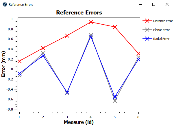
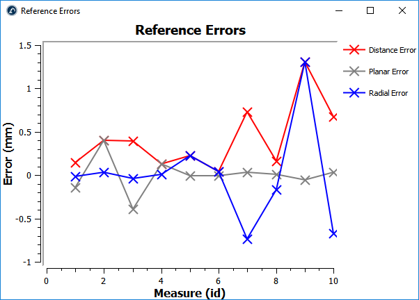
9.Select Show Errors to display the error level at each point (the distance errors are equivalent to the planar errors and the radial errors combined)
Calibrate a two-axis Turntable
This section guides you to calibrate a 2-axis turntable. You can calibrate your 2-axis turntable using a well-defined TCP and a static point on the turntable.
Follow this procedure to calibrate your 2-axis turntable.
1.Add a new coordinate system attached to the robot called Calibrated Frame: right click on the robot base and select Add Reference Frame. Then, press F2 to rename it accordingly.
2.Place the base of the turntable attached to the Calibrate Frame as shown in the attached image: you can right click on the turntable base frame and click on Change Support, then, select the Calibrated Frame reference.
Important: The calibrated reference should be static. This means it should be directly attached to the robot base. You should then attach the base of your turntable to the calibrated reference and translate the base along the nominal distance (the distance between the floor and the intersection of axis 1 and 2 of the turntable). With this setup, if you move the turntable or want to recalibrate the turntable you simply must repeat the calibration procedure again and everything else is updated automatically.
3.Richt click on the Calibrated Frame and select Define Reference Frame.
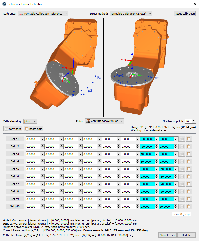
4.Select the method Turntable Calibration (2 Axes)
5.Select Calibrate using joints (default setting). You can change it to points (instead of joints) if you have the XYZ position of each point with respect to the robot base frame.
6.Specify the robot if more than one robot is available in the station.
7.Select the number of points you would like to take (the minimum required is 6 points: 3 points for each axis).
Important: You should probe the same point of the turntable with the robot tool, as you move the turntable. You should move the turntable along the positive sense of rotation for each axis. You should first move axis 1, then, axis 2 (as shown in the previous picture). It is recommended to use a minimum of 10 points to have a better understanding of the errors involved in moving the turntable.
Note: The number of points used to identify axis 1 doesn’t need to match the number of points used to identify axis 2 (for example, you can use 4 points to identify axis 1 and 6 points to identify axis 2).
Important: The Z axis of the calibrated reference will match axis 2. The X axis of the calibrated reference will match the common normal. Also, the origin of the calibrated reference will be placed at the intersection between axis 2 and the common normal (point on axis 2 that is closest to axis 1).
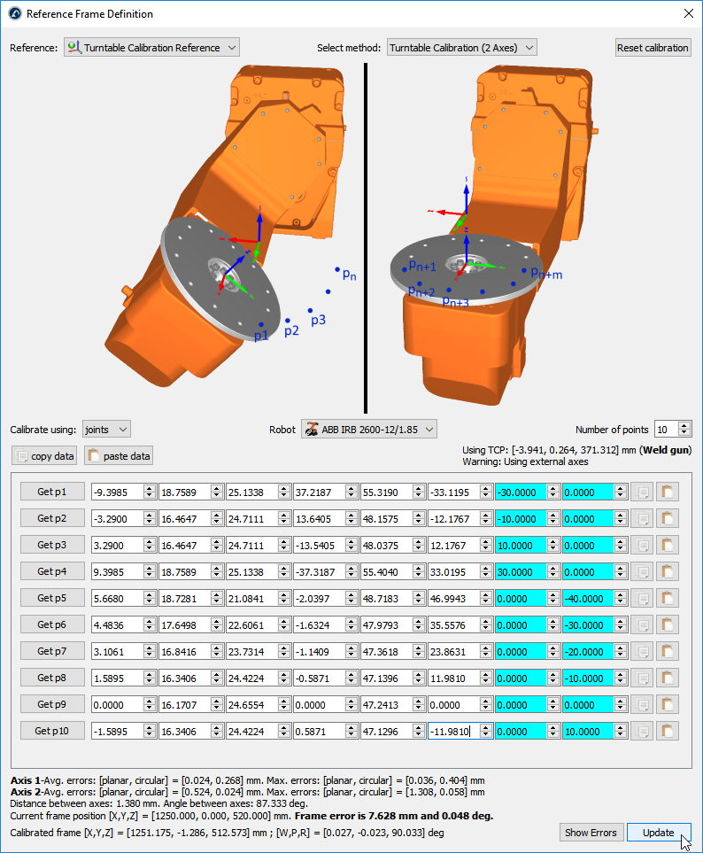
8.Start filling the table with the robot joint positions (or points).
Tip: The list of configurations can be filled manually or by using the copy/paste buttons (buttons at the right of the joint values).
Tip: If you are connected to the robot you can select the “Get p” buttons to retrieve the robot joints directly from the robot. More information to set it up is available in the Robot Drivers Section. This option is not available for all robots and it may require additional software options sold by the robot manufacturer.
Important: If you enter the values manually it is recommended to provide each joint value with at least 4 decimals (when providing joint values). The allowed number of decimal values can be changed in Tools➔Options➔Accuracy➔Max Decimals.
Note: RoboDK will keep a copy of the provided data in the RDK station once you select update.
9.Finally, select Update to apply the new position to the reference frame selected in the RoboDK Station.
10.Select Show Errors to display the error level at each point (the distance errors are equivalent to the planar errors and the radial errors combined)