Define a Reference Frame
A Reference Frame defines the position of an object with respect to a robot (position and orientation). It is recommended to teach targets with respect to a reference that you can define with your robot. A reference frame allows you to adjust or move your programs to different locations without having to re-teach all your targets.
More information about reference frames is available in the Getting Started Section.
Defining a reference frame requires probing some points using a robot tool (the joint values need to be retrieved at specific locations).
Follow these steps to identify a reference frame with respect to the robot:
1.Select Utilities➔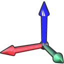
2.Select the Reference Frame to define/calibrate.
Alternatively, right click a Reference Frame and select 
3.Select the method:
a.3-point method (with the 3rd point crossing the Y+ axis)
b.3-point method (with the 1st point being the origin of the reference frame)
c.6-point
d.The Turntable Calibration option allows locating the reference frame on a turntable, having the turntable axis properly aligned
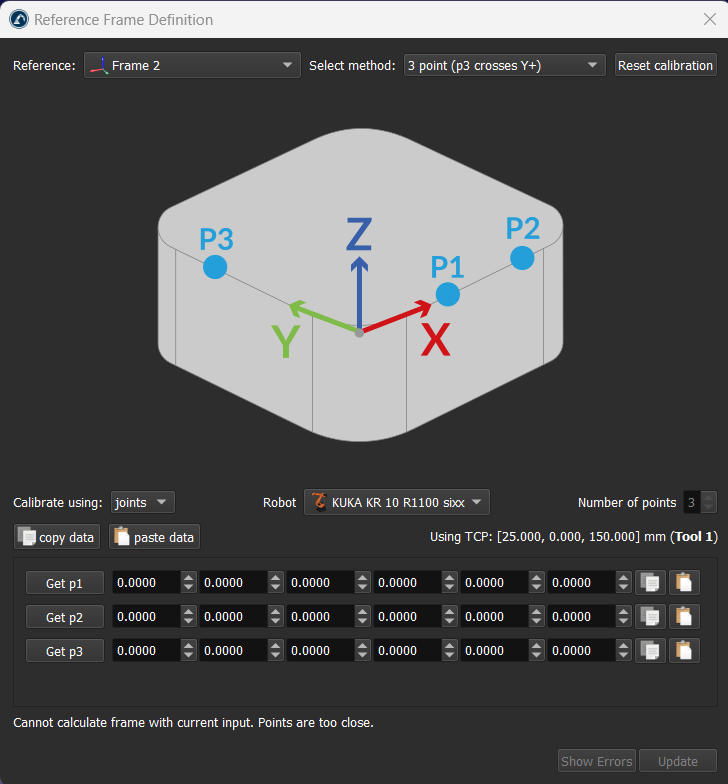
4.Joint values are used as the default setting. Change it to points if you have the XYZ position of each point with respect to the robot base frame.
5.Select the robot if more than one robot is available.
6.Start filling the table with the measured points (joint values or points).
7.Finally, select Update to apply the new position to the reference frame selected in the RoboDK Station.
Align object with reference
This section explains how the reference frame (coordinate system) of an object can be aligned with respect to its own geometry. This section allows moving the reference frame of an object to a location that can be identified in a real setup.
Follow these steps to virtually align the reference frame of an object according to specific points of the object geometry:
1.Load the object
2.Select the active 
3.Select Program➔
Make sure the reference frame is directly attached to the station root (not to other Reference Frames).
4.Right click the reference frame and select
The procedure is very similar to the previous section. The main difference is that we must select the points of the virtual object instead of the real object.
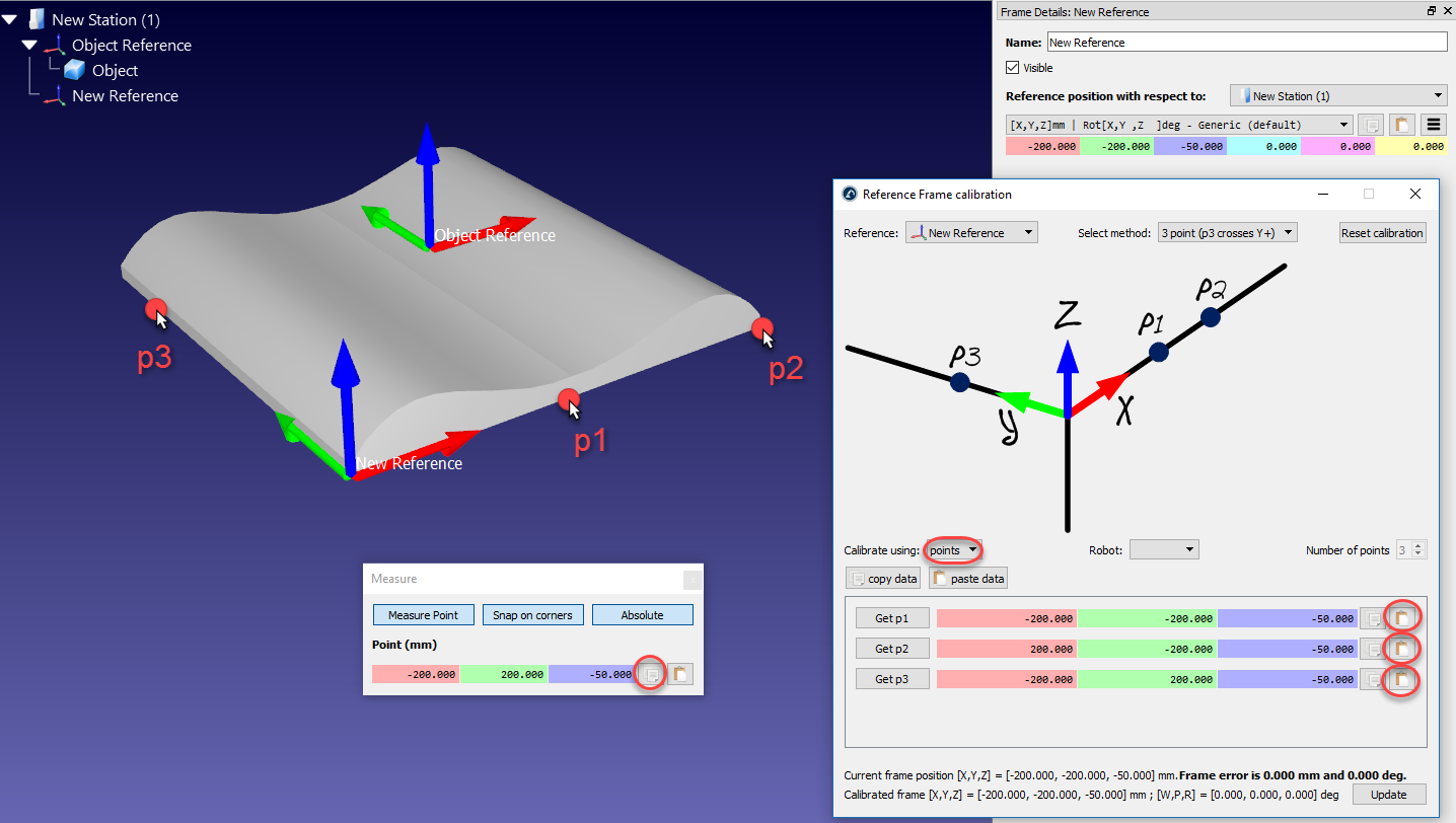
5.Select the desired calibration method.
For example: The 3-point method (with the 3rd point crossing the Y+ axis).
6.Select Calibrate using points
7.Select Tools➔Measure to open the Measurement Tool
8.Select the Absolute button in the Measurement Tool so that the points are measured with respect to the Station (absolute reference)
9.Select the 3 points on the virtual object (one by one) and enter them in the Reference Frame calibration window
10.Select Update. The reference frame should appear at the desired location.
11.Right click the object and select Change support. Then, select the new reference frame. The absolute position of the object will not change. However, the relative position of the object with respect to the new reference frame will be properly defined.
12.The object and its own reference are ready for Offline Programming: Drag and drop the new reference frame to the robot reference frame.
Align robot references
This section explains how two or more robots can be programmed offline while sharing a common reference frame.
In a typical offline programming application, the position of the object is updated with respect to the robot. However, when two or more robots are used for the same application, the position of each robot must be updated with respect to one common reference (a reference object or a common reference frame).
Follow these steps to update the position of two or more robots with respect to a reference frame:
1.Make sure the robot reference frames and the object reference frame do not depend on each other. If there is a dependency we should place the reference frames attached to the station item.
2.Add a new reference frame attached to each of the robot base frames as if you were going to define a new individual reference frame for each robot (Real Ref. A and Real Ref. B).
This reference frame will represent the real location of the part with respect to each robot.
3.Calibrate each of these reference frames (Real Ref. A and Real Ref. B), separately, using the standard Reference Calibration procedure (3-point method for example)
At this point we will see 3 reference frames that should be coincident, but they are not. The reference frame of each robot must be updated to fix this issue:
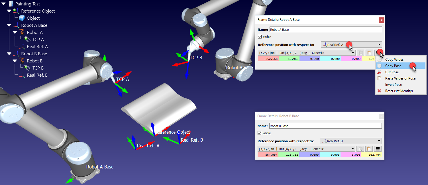
4.Double click one of the robot references, such as Robot A Base to open the reference frame window
5.Copy the position of the robot base reference with respect to the calibrated reference of that robot (Real Ref. A), by selecting the copy button
6.In the same window, change the Reference position with respect to (dropdown) to the Reference Object
7.Paste the copied position. The robot will be moved and the Real Ref. A will be coincident with the Reference Object frame
8.Repeat steps 4-7 of this procedure for the other robots, if any
At the end of this procedure all reference frames should match and the relationship between all the calibrated references and the Reference Object should be the same.