Create a Tool
New robot tools (TCPs) can be loaded or created in RoboDK from previously loaded 3D geometry.
Follow these steps to load an object and set it up as a robot tool:
1.Select File➔
2.Select the Paint gun.stl file to add it as an object (it will be added at the robot base frame)
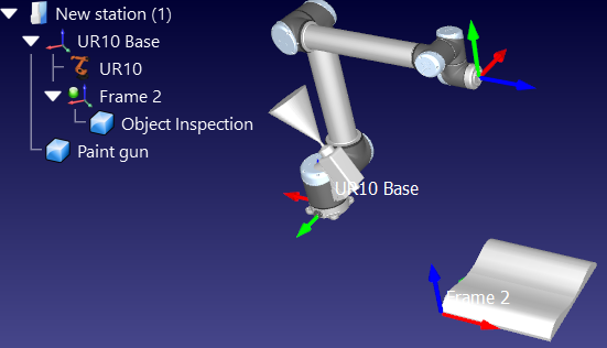
3.Drag & drop the object to the robot item inside the station tree as shown in the next image
New tools can be loaded or saved as a .tool format.
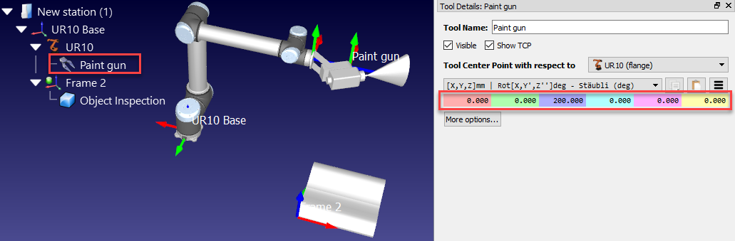
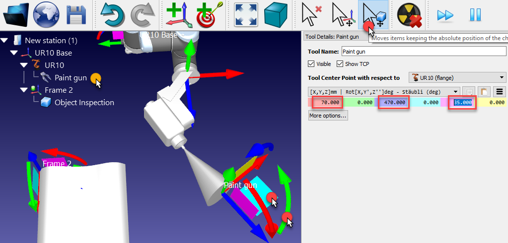
By default, RoboDK will define the TCP at the position [X,Y,Z]=[0,0,200] mm. This can be changed by entering the coordinates manually and/or by moving the TCP holding the ALT+Shift key as shown in the next image:
1.Hold ALT+Shift or select the highlighted button from the toolbar
2.Select the light blue plane (XZ plane of the TCP) and drag the TCP approximately towards the surface of the spray gun, as shown in the next image
3.Select the Green rounded arrow (rotation around the Y axis) to make the Z axis point outwards
4.Once an estimate of the coordinates is obtained it is possible to touch up these values manually by double clicking the Paint gun object. The mouse wheel can be used on top of each case to quickly update the position on the main screen.
At this point, the station can be saved:
1.Select File➔
2.Save the file as Paint Test.rdk. The Window title and the Station name will be updated
Set a relative TCP
You can reference a tool (TCP) with respect to another one, for example, to define a given standoff or to place a cutter with respect to a reference or tool holder.
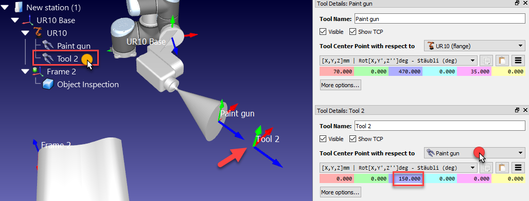
These steps assume that a second TCP must be added with respect to the first one at 150 mm along the Z axis:
1.Right click the robot
2.Select 
3.Double click this new TCP
4.Select Tool Center Point with respect to ➔Paint gun
5.Enter the coordinate Z to 150 mm and set the other translations and rotations to 0.
This new TCP relative to the previously defined TCP will be removed in the next sections of this demonstration.
Move the Tool geometry
The geometry of the tool might not be aligned properly with respect to the robot flange (adaptor reference frame) when it is loaded in RoboDK.
The following steps assume that a mistake was made, and the tool was mounted 180 degrees around the Z axis, so the following correction should be applied:
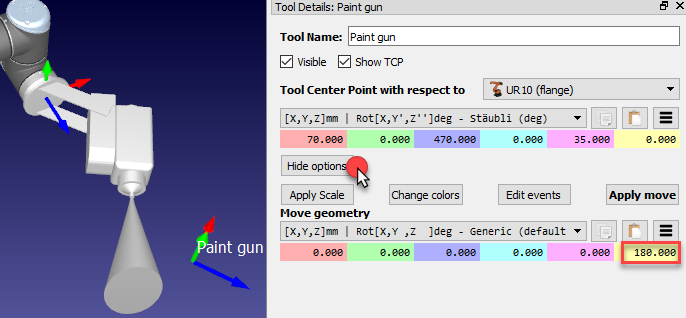
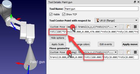
1.Select More options in the Tool details window
2.Enter 180 in the yellow case (Z rotation) of the paint gun geometry, as shown in the following image. The mouse wheel can be used on top of each case to quickly update the position on the main screen.