Getting Started
This getting started guide will help you create a simple project in RoboDK for robot simulation and offline programming. This example shows how you can simulate and program a robot arm for a robot painting application.
This example also provides an overview of basic robot concepts, such as how to use reference frames, tools and targets.
The examples section provides more examples for many different applications. For example: robot machining, polishing or welding.
New RoboDK project
All robots, objects and tools used in a RoboDK project are saved as a RoboDK station (RDK file). A RoboDK station contains all settings related to robots, tools, reference frames, targets, objects and other parameters. The RoboDK station is stored in one file (RDK extension).
It is not required to keep a separate copy of the robot files, tools and objects as they are saved as one RDK file.
Follow these steps to create a new RoboDK project (RDK station):
1.Download and install RoboDK from the website: https://robodk.com/download.
2.Double click the shortcut on the Desktop 
3.If other stations are open:
select File➔ 
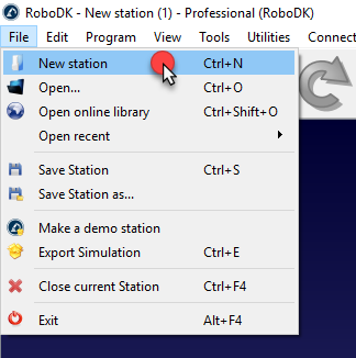
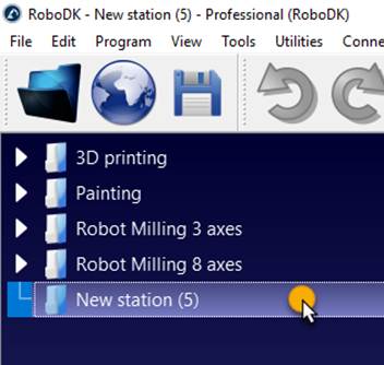
Multiple RoboDK projects can be open at the same time. Double clicking the Station icon
https://www.youtube.com/watch?v=uxlfxglE2YE&index=2&list=PLjiA6TvRACQd8pL0EnE9Djc_SCH7wxxXl.
Select a robot
New robots can be added to your project from your PC or from RoboDK’s online library.
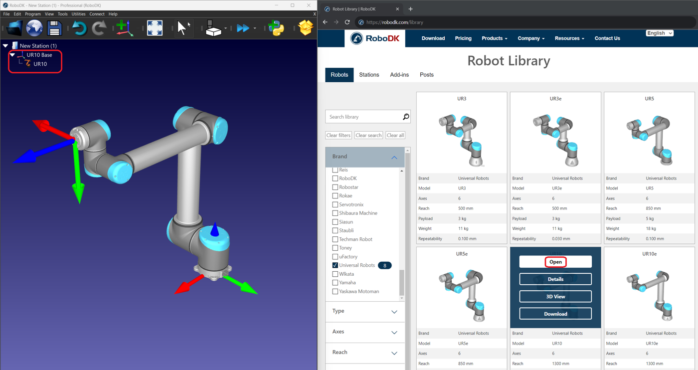
Follow these steps to choose a robot from the online library:
1.Select File➔
2.Use the filters to find your robot by brand, payload, etc. In this example, we’ll use a Universal Robots UR10 robot (10 kg payload robot and 1.3 m reach).
3.Select Open and the robot should automatically appear in the station in a few seconds. Alternatively, you can download the robot file and open it in RoboDK by drag and dropping the file into the window.
4.The online library can be closed once you loaded your robot.
The default location of this example project is: C:/RoboDK/Library/Tutorial-UR-Painting.rdk.
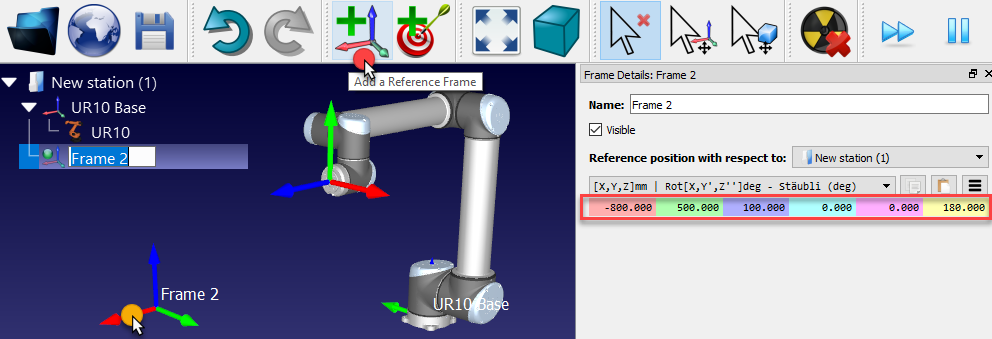
Add a Reference Frame
A Reference frame (or also called a coordinate system) allows placing objects with respect to a robot or with respect to other objects in the 3D space (including position and orientation).
Follow these steps to add a new reference frame:
1.Select Program➔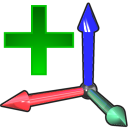
Alternatively, select the equivalent button in the toolbar
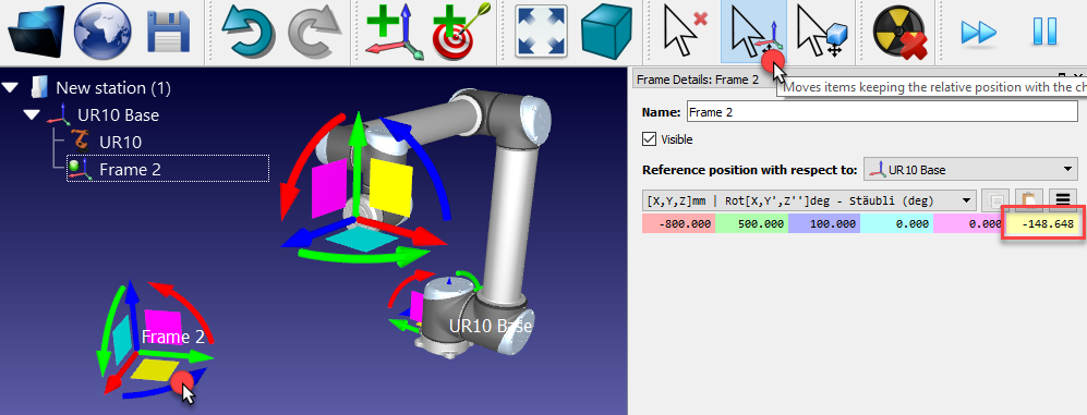
2.Double click the reference frame (on the tree or on the 3D geometry on the main screen) to enter the coordinates shown in the image (X,Y,Z position and Euler angles for the orientation). The mouse wheel can be used on top of each case to quickly update the position of the reference frame on the main screen.
The following colors are used by default:
●X coordinate ➔ Red.
●Y coordinate ➔ Green.
●Z coordinate ➔ Blue.
●1st Euler rotation ➔ Cyan.
●2nd Euler rotation ➔ Magenta.
●3rd Euler rotation ➔ Yellow.
3.Select View➔Make reference frames bigger (+) to increase the size of the reference frames.
4.Select View➔Make reference frames smaller (-) to decrease the size of the reference frames.
5.Select View➔Show/Hide text on screen (/) to show or hide the text on the screen.
6.Optionally, rename any reference frame or object in the tree by selecting F2.
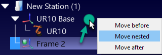
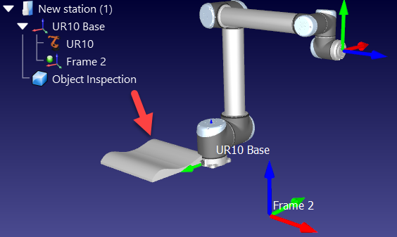
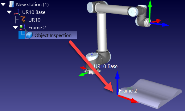
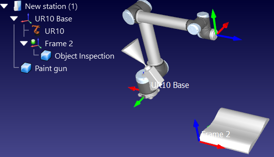
If more than one reference frame is used, it is possible to drag and drop them inside the Station Tree to match the dependency that exists in the real setup. For example, the reference Frame 2 may be placed with respect to the robot base reference. In this case, if the UR10 Base reference is moved, Frame 2 is also moved with it. It is important to take this into account if other robots or reference frames are used. The next image shows the difference in dependency.
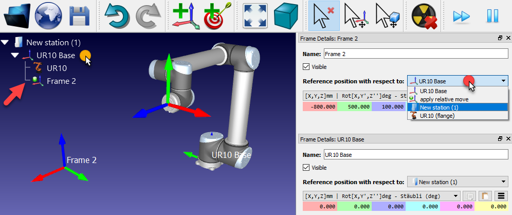
Even if the dependency is different, it is still possible to enter or retrieve the coordinates of any reference frame with respect to any other reference frame, as shown in the next image. Most robot controllers require the coordinates of the reference frame with respect to the robot base frame.
Reference frames can also be moved in the main screen by holding the Alt key, or selecting the corresponding button in the toolbar 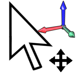
Import 3D objects
RoboDK supports most standard 3D formats such as STL, STEP (or STP) and IGES (or IGS) formats. Other formats such as VRML, 3DS or OBJ are also supported (STEP and IGES are not supported on Mac and Linux versions).
Follow these steps to load a new 3D file:
1.Select File➔
2.Select the object Object Inspection available in RoboDK’s default library:
C:/RoboDK/Library/Object Inspection.
3.Alternatively, drag & drop files into RoboDK’s main window to import them automatically
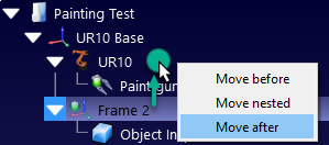
4.Drag & drop the object to the reference frame Frame 2 (inside the station tree)
Tools➔Options➔CAD➔Fast import settings. More information available in the STEP/IGES section.
Create a Tool
New robot tools (TCPs) can be loaded or created in RoboDK from previously loaded 3D geometry.
Follow these steps to load an object and set it up as a robot tool:
1.Select File➔
2.Select the Paint gun.stl file to add it as an object (it will be added at the robot base frame)
3.Drag & drop the object to the robot item inside the station tree as shown in the next image
New tools can be loaded or saved as a .tool format.
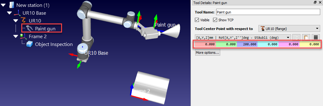
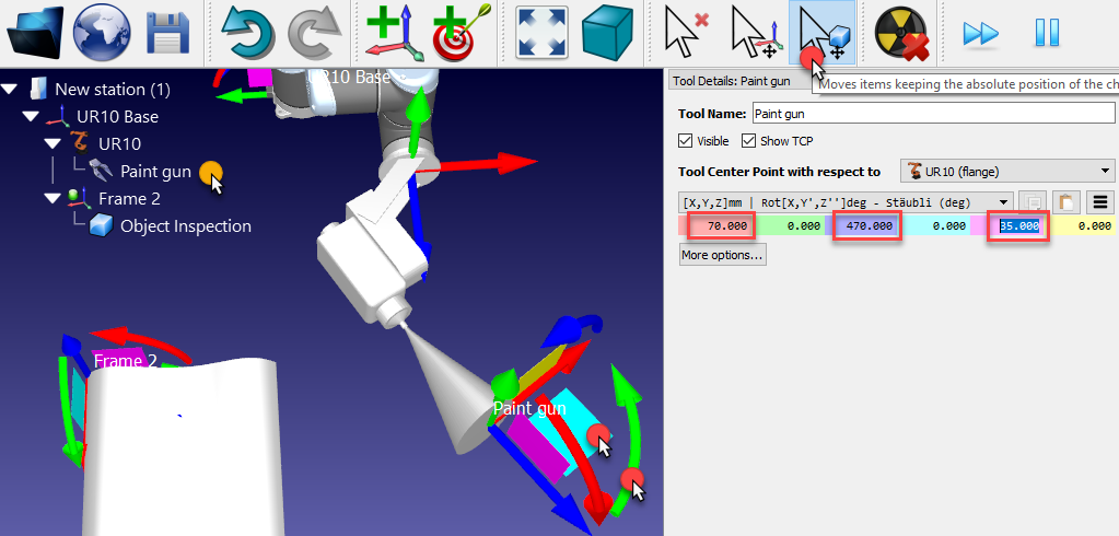
By default, RoboDK will define the TCP at the position [X,Y,Z]=[0,0,200] mm. This can be changed by entering the coordinates manually and/or by moving the TCP holding the ALT+Shift key as shown in the next image:
1.Hold ALT+Shift or select the highlighted button from the toolbar
2.Select the light blue plane (XZ plane of the TCP) and drag the TCP approximately towards the surface of the spray gun, as shown in the next image
3.Select the Green rounded arrow (rotation around the Y axis) to make the Z axis point outwards
4.Once an estimate of the coordinates is obtained it is possible to touch up these values manually by double clicking the Paint gun object. The mouse wheel can be used on top of each case to quickly update the position on the main screen.
At this point, the station can be saved:
1.Select File➔
2.Save the file as Paint Test.rdk. The Window title and the Station name will be updated
Set a relative TCP
You can reference a tool (TCP) with respect to another one, for example, to define a given standoff or to place a cutter with respect to a reference or tool holder.
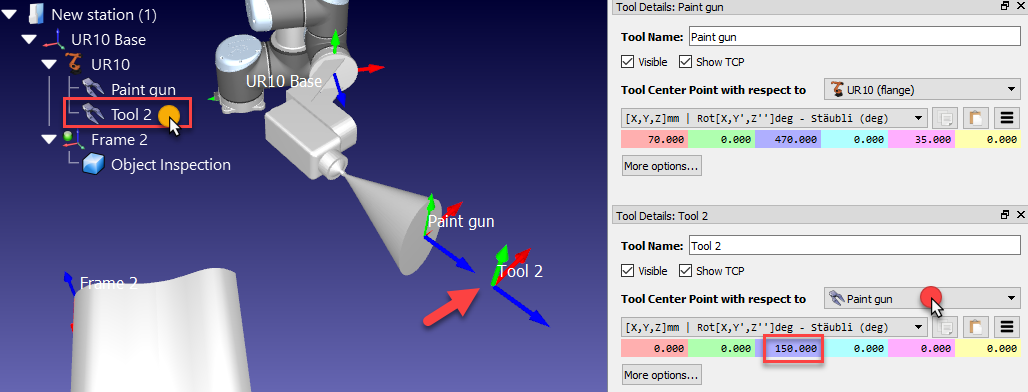
These steps assume that a second TCP must be added with respect to the first one at 150 mm along the Z axis:
1.Right click the robot
2.Select 
3.Double click this new TCP
4.Select Tool Center Point with respect to ➔Paint gun
5.Enter the coordinate Z to 150 mm and set the other translations and rotations to 0.
This new TCP relative to the previously defined TCP will be removed in the next sections of this demonstration.
Move the Tool geometry
The geometry of the tool might not be aligned properly with respect to the robot flange (adaptor reference frame) when it is loaded in RoboDK.
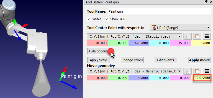
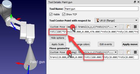
The following steps assume that a mistake was made, and the tool was mounted 180 degrees around the Z axis, so the following correction should be applied:
1.Select More options in the Tool details window
2.Enter 180 in the yellow case (Z rotation) of the paint gun geometry, as shown in the following image. The mouse wheel can be used on top of each case to quickly update the position on the main screen.
Create Targets
Robot positions are recorded as Targets. A Cartesian target defines the position of the tool with respect to a coordinate system. A Joint target defines the position of the robot given robot joint values.
Follow these steps to create two targets as a new home target and approach target respectively:
1.Double click the robot to show the robot panel.
2.Select Paint gun as the Tool Frame. Once a tool or a reference frame becomes active it will show a green dot in the tree icon.
3.Select Frame 2 as the Reference Frame.
4.Hold the Alt key and move the robot by dragging it through the TCP or the robot flange to a safe position, free of collisions with any objects. Alternatively, move the coordinates of the Tool Frame (TCP) with respect to the reference Frame.
5.Use the Other configurations section to switch between different robot configurations and make sure that none of the robot axes are close to the axis limits.
6.Select Program➔
In this example, the robot joint coordinates used for the first target are: [-150, -75, -90, -60, 70, 110] deg. You can copy these joint values from the text and paste 
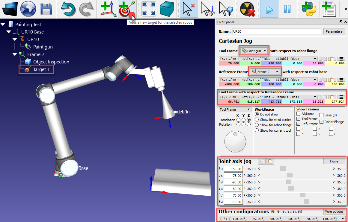
7.Rename the first target as Home by pressing F2. Alternatively, select Tools➔Rename item.
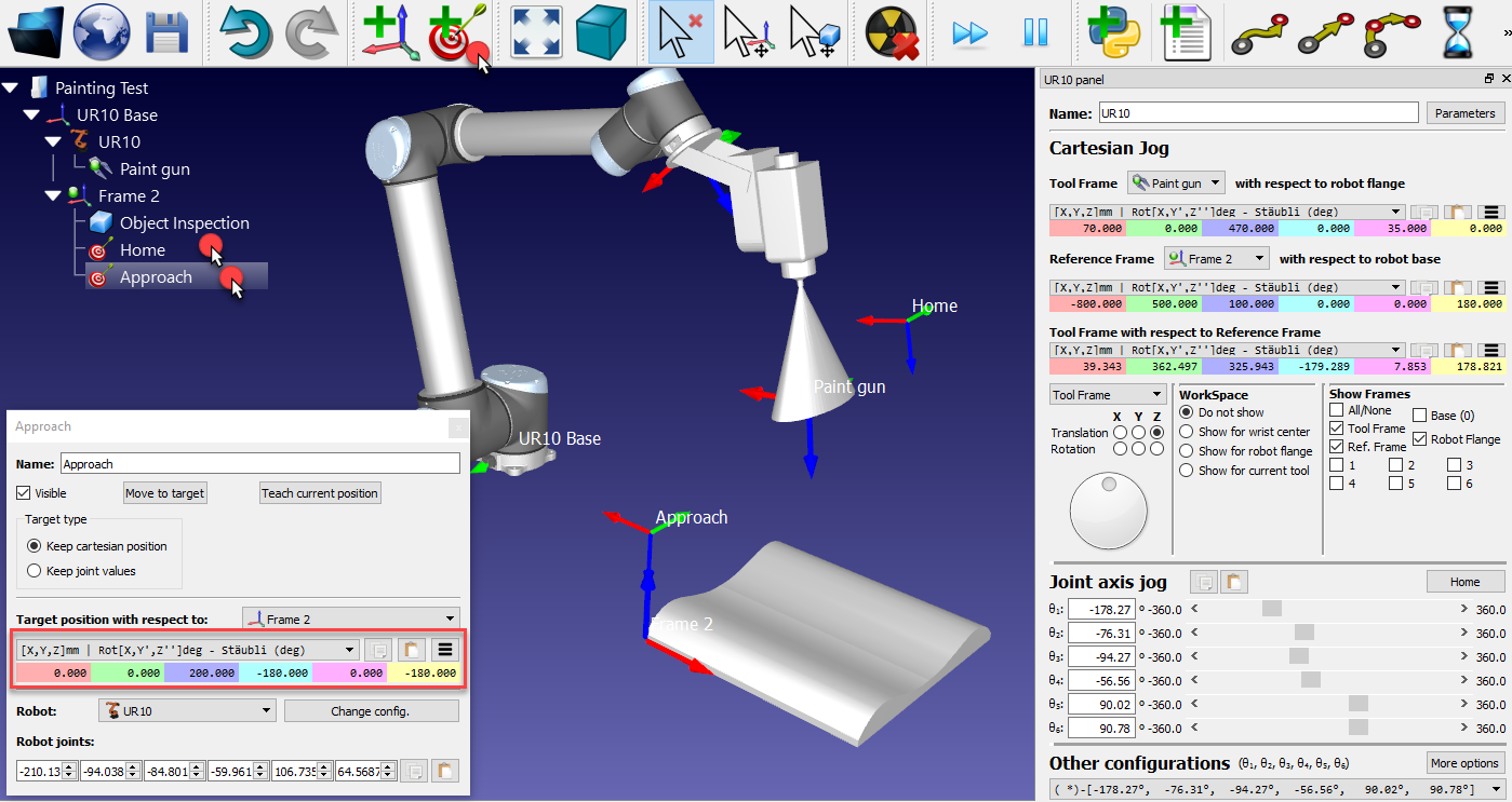
8.Move the robot closer to one edge of the part (by dragging the tool using the Alt key, entering coordinates or jogging the axis manually). In this example we used the following robot joint coordinates [0,0,200,180,0,180] deg.
9.Select Program➔
10.Rename the target to Approach as shown in step 7.
11.Select the Home target and the Approach target alternatively to see the robot moving between the two targets.
12.Right click the target and select Teach Current Position (Alt+double click) if a different position needs to be recorded for one of the targets.
13.Right click the target and select 
If required, provide different values to define the targets.
Add an Approach Program
You can easily create a new program that safely approaches the robot to the part.
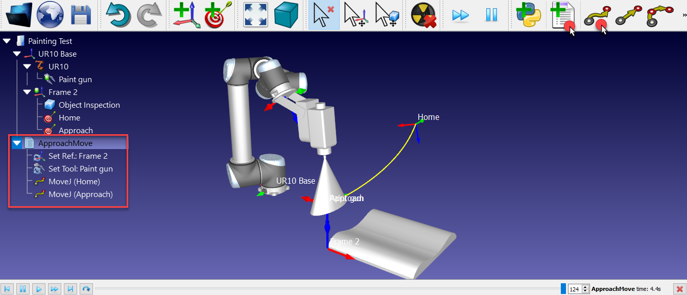
Follow these steps to create a program that moves from the Home target to the Approach target:
1.Select Program➔
2.Rename the program to ApproachMove.
3.Select the Home target.
4.Select Program➔
Two instructions will be added automatically to tell the robot what tool frame and reference frames we are using.
5.Select the Approach target
6.Select Program➔
Double click the ApproachMove program and it will execute the program simulation. The simulation bar and an estimated cycle time will be displayed.
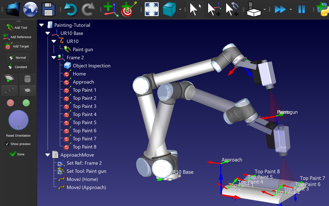
Create Targets on Surface
The Create Targets on Surface feature is useful for applications such as painting or inspection.
Follow these steps to teach targets using the Teach Target(s) on Surface:
1.Select Program➔
2.Move the mouse cursor over the part to see a preview of what the robot looks like when it reaches the part.
3.Select a few points on the object (left click). Each mouse left click will define a new target keeping the Z axis of the TCP normal to the surface (perpendicular to the surface).
4.If necessary, adjust the orientation around the Z axis by moving the wheel on the left panel or pressing the left/right keys.
5.Hold Alt to move an existing target.
6.Hold Alt+Shift to move an existing target while keeping it on the surface.
7.Select Esc key or right click on the screen and select Done to exit the Create Targets on Surface mode.
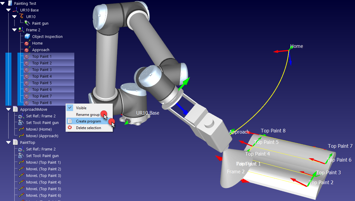
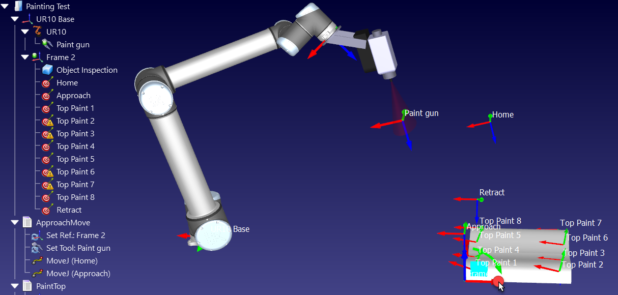
Once the targets have been created, generate a program following these steps:
1.Select all the targets created on the surface and right click.
2.Select Rename group from the pop-up menu.
3.Enter Top Paint. All selected targets will be renamed and numbered.
4.Right click on the targets again and select Create Program. A new program will be generated. The first movement will be a joint move and following movements will be linear.
5.Select F2 to rename the program to PaintTop.
6.Double click the PaintTop program to see the simulation moving along the targets.
7.If required, reorder the movements by dragging the move instructions inside the program.
Add a Retract Program
You can easily create a new program that safely retracts the robot from the part to a safe position.
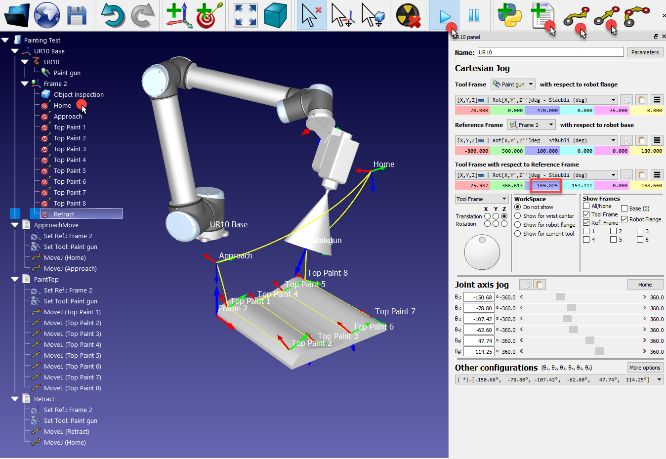
Similar to the previous operations:
1.With the robot placed at the last target, move the robot upwards by increasing the Z coordinate of the TCP with respect to the reference frame in the robot panel (highlighted case in the next image).
2.Select Program➔
3.Select Program➔

4.Select the Home target
5.Select Program➔
Simulate each program individually by double clicking it. The simulation can be accelerated by holding the Spacebar key or selecting the Fast Simulation button 

Main Program
You can easily create a main robot program that executes the approach, paint and retract programs sequentially.
Follow these steps to create the main program:
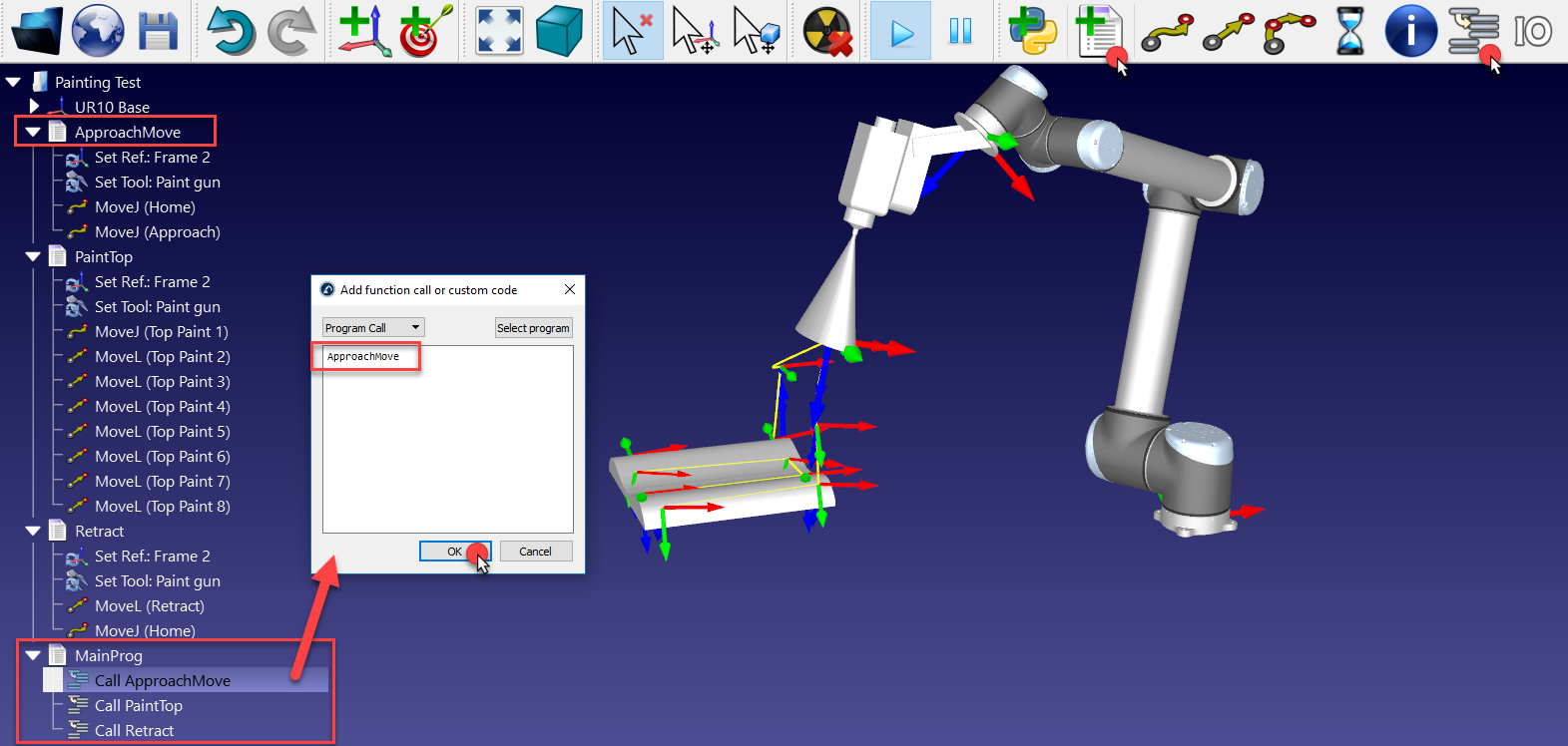
1.Select Program➔
2.Select Program➔
3.Enter the name ApproachMove or select Select program to automatically select it.
4.Select OK.
5.Repeat the previous steps for PaintTop and Retract as shown in the next image
Double clicking the Main Program will run the complete simulation. Right click the Main Program and select Loop to make it simulate in a loop.
If the reference frame Frame 2 is moved (for example, by holding Alt key and dragging the X/red axis of the reference frame), the object and targets will follow. If the targets become not reachable, a small warning sign will be displayed on the target icon 
Generate a Robot Program
Once you have the simulation ready in RoboDK you can easily generate the robot program. The robot program allows you to run the program on the robot controller without having to write a single line of code.
Follow these steps to generate a robot program:
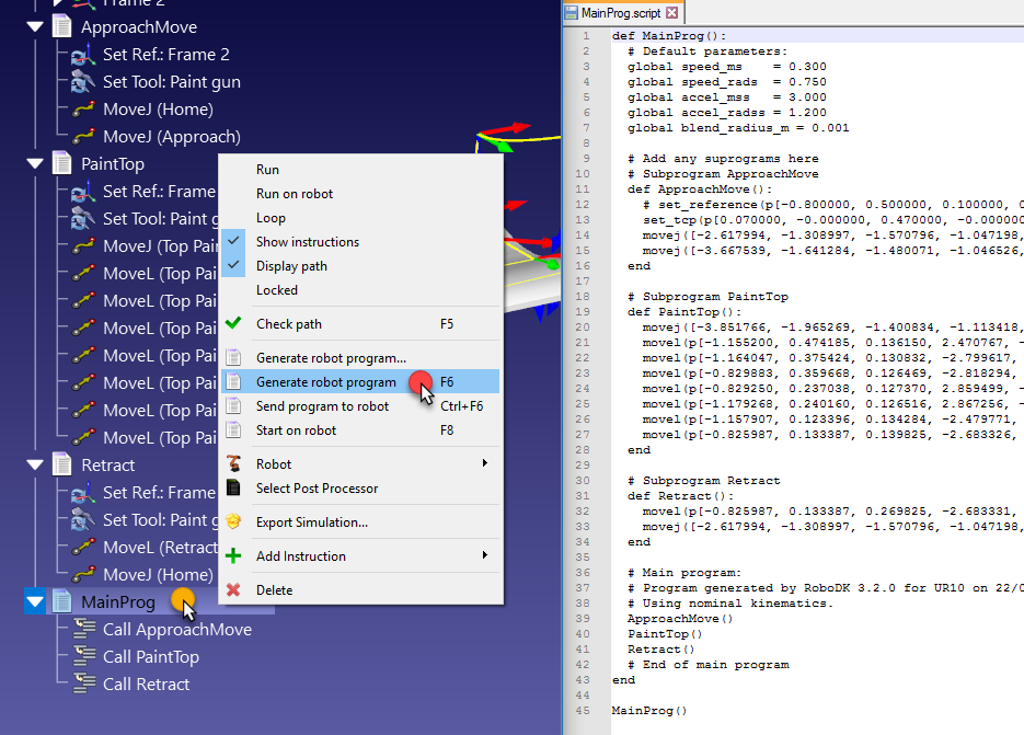
1.Right click the program (MainProg for example). You can also hold Ctrl to select multiple programs at once to generate them.
2.Select Generate robot program (F6). Alternatively, you can select Generate robot program as… to specify the location to save the file.
You should then see the robot program displayed in a text editor.
You can find more information about how to generating robot programs in the Programs section.
In this example, you’ll obtain the SCRIPT program file for your UR robot. For Universal Robots specifically, you can export any program individually or the main program including the subprograms.
The file you obtained is the result of generating the program offline. The file can be sent to the robot controller to run the same movements that were simulated in RoboDK.
It is possible to change the post processor for UR robots and customize the way a program is generated:
1.Right click a program or a robot.
2.Select 
3.Select Universal Robots URP.
Generate the program again. In this example, the default post processor uses joint values to define each linear move and the second post processor uses cartesian coordinates to define each linear move.
Using Scripts
You can customize your simulation by using scripts. The RoboDK API allows you to customize the simulation as much as desired. RoboDK integrates with Python and by using a sample script or using the RoboDK API you can improve the result of your simulation.
By default, RoboDK installs Python and a set of sample scripts that allow you to improve simulations. This includes simulating a paint gun, simulating 2D cameras, converting SVG files to robot programs, automatically setting a TCP given a standoff, programming robots using Python, simulating discrete events, etc. Other programming languages can also be used, such as C#, C++ or Matlab. More information is available in the RoboDK API section.
In this example, we will add an existing sample script that will simulate the behavior of the paint gun. You can also change the color of the spray with a transparent color (by selecting Tools➔Change color tool - Shift+T) or load the existing model with appropriate colors (available from the local library as paint_gun.tool or the online library, note that the Set Tool instruction might need to be updated to link to the new tool).
1.Select File➔
2.Navigate to C:/RoboDK/Library/Macros/ to see some sample macros.
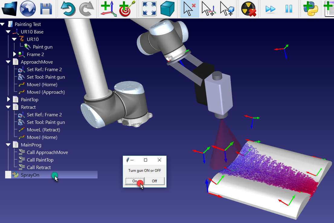
3.Select SprayOn.
4.Select Open. A new Python object 
5.Double click the SprayOn macro to test it.
6.Select On to activate it.
7.Hold Alt key, drag the robot flange and move the robot along the surface with the Paint gun.
You should see the trace of the paint gun. The color and transparency should change depending on how close or far the TCP is from the surface.
Select Esc once to clear the simulated paint.
8.Double click the same SprayOn program and select Off to turn the particle simulation Off.
To better understand what happens behind the scenes, it is possible to view or edit the Python code the following way:
1.Right click
2.Select Edit Python Script.
A new window (text editor) will appear showing the code that models the spray behavior and how Python is integrated with RoboDK.
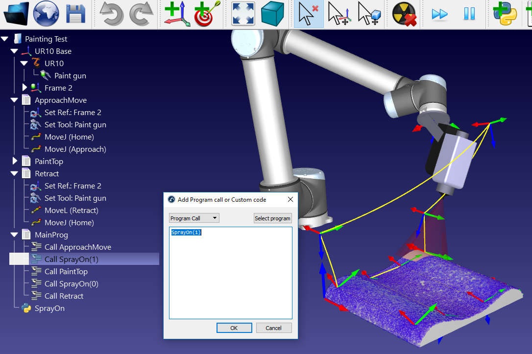
To take the spray simulation into account in the main program we can follow these steps:
1.Right click the instruction Call ApproachMove.
2.Select Add Instruction➔
3.Enter SprayOn(1).
4.Select OK.
5.Repeat the same operation after the PaintTop program setting SprayOn(0), as shown in the following image.
If necessary, reorder the instructions by drag & dropping them within the program.
6.Run the MainProg program. After two iterations, the result should look like as shown in the image (simulating at normal speed).
It is also possible to create new macros:
1.Select Program➔
2.Right click the new program and select Edit Python Script.
RoboDK supports setting the robot speed within the program, setting digital outputs, waiting for digital inputs, displaying messages, etc. These instructions are available under the Program menu.