The Main menu is divided in the following sections:
1.File menu: Allows importing new files (3D geometry, robots, tools, toolpaths, …) and opening or saving RoboDK projects (RDK file extension).
2.Edit menu: Allows to cut/copy/paste an item or a group of items and do undo/redo actions.
3.Program menu: Allows creating or modifying robot programs and other related options for Offline Programming (OLP).
4.View menu: Provides useful actions to navigate in 3D and set up specific views.
5.Tools menu: Provides general tools such as checking for collisions, measuring points, or opening the main options.
6.Utilities menu: Allows performing specific operations such as using robots for manufacturing operations, calibrating a TCP or a reference frame, using robots as a 3D printer or as a 5-axis CNC, calibrate a robot... These operations might require a specific license option.
7.Connect menu: Allows connecting to a robot, a measurement system or simulate cameras.
8.Help menu: Allows opening the online documentation (F1), check for updates or set up a license.
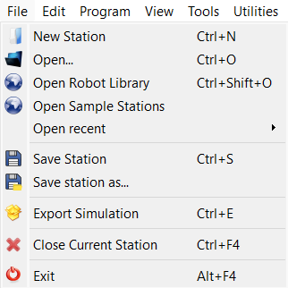
File Menu
The File menu of RoboDK allows you to open and save RoboDK projects. You can also load any type of file supported by RoboDK or export your project using different formats or methods.
New Station will add a new station in the tree. One station can be loaded or saved as one RDK file. The RDK file (RDK extension) holds all the information about the robots and objects so it is not required to keep a separate copy of the imported items.
Tip: It is possible to have more than one Station open at the same time. Double clicking the station icon in the tree will display that station.
Open will load a new RoboDK file (RDK Station) or import any other recognized file formats, such as .robot for robot files, STEP/IGES/STL for objects, .tool for tool files, etc.
Open online library will show a new window with the library available online.
Save Station will save the RDK file. Select Save Station as… to provide the file location.
Export Simulation will export a specific program or simulation as a shareable RoboDK for Web link, a 3D PDF, 3D HTML file. This example shows the export of a 3D HTML simulation.
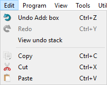
Edit Menu
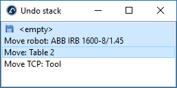
Undo (Ctrl+Z) and Redo (Ctrl+Y) actions are accessible from the Edit menu. The history of undo actions is also available and allows reverting changes, backwards or forward, to a specific state by selecting the action.
It is also possible to cut (Ctrl+X), copy (Ctrl+C) or paste (Ctrl+V) one item or a group of items from the station tree. If an item is copied, all the items attached to it are also copied.
Tip: It is possible to group similar actions in one. For example, if the robot is moved manually, every small step is recorded (by default). To group all the small steps in one: select Tools➔Options➔check Bundle similar actions together.
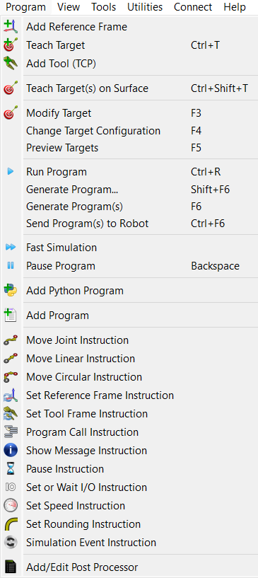
Program Menu
The program menu contains all the components related to Offline Programming (OLP) and program generation. It is possible to add new programs, reference frames, targets or tools to robots. These Offline Programming components (reference frames, tools, targets, etc.) appear on all programs generated offline.
Add Reference Frame will add a new reference frame attached to the station root or attached to another reference frame if that reference frame was selected.
Add empty tool will add a new TCP to a robot. No geometry is required to add a new tool. Multiple Tools allow referencing different parts of the same geometry linked to one tool.
Teach Target (Ctrl+T) will add a new target to the Active reference frame for the Active robot tool. The active reference frame and active tool can be selected in the robot panel. It is also possible to right click a reference frame or a tool to make them active.
Teach Targets on Surface (Ctrl+Shift+T) will allow the user to select points of an object to easily create targets. An example is available in this section.
Add Program will add a new program that can be created using the RoboDK Graphical User Interface (GUI). No programming experience is required to create or modify this type of robot program. The robot program can be simulated and generated for a specific robot, automatically and easily.
The Program Instructions section of the Offline Programming document provides more information about available program instructions through the GUI.
Add Python Program option will include a sample Python program/macro/script/module in the station that links to the RoboDK API. A Python program using the RoboDK API allows creating robot programs from generic programming code (Python). It is possible to deploy these programs for any specific robot controller. It is also possible to simulate specific tasks to extend the GUI programs. These tasks can be robot subprograms for offline programming, online programming or simply simulate specific events such as making objects appear automatically at random spots for a pick and place simulations. A Python program is like a text file embedded in the station and contains Python code to automate specific tasks in RoboDK. The RoboDK API is deployed using Python by default but other programming languages can be used to interface with RoboDK.
Note: The difference between a normal program (using Add Program) generated using the Graphical User Interface (GUI) and a Python program (using Add Python Program) is that the first does not require programming experience. On the other hand, a Python macro using the RoboDK API allows extending the limits of a program generated using the graphical user interface.
Finally, it is possible to Add or Edit Post Processors. Post Processors define the way programs are generated for a specific robot controller, allowing to accommodate vendor-specific syntax. Post Processors are final component of the offline Programming Process.
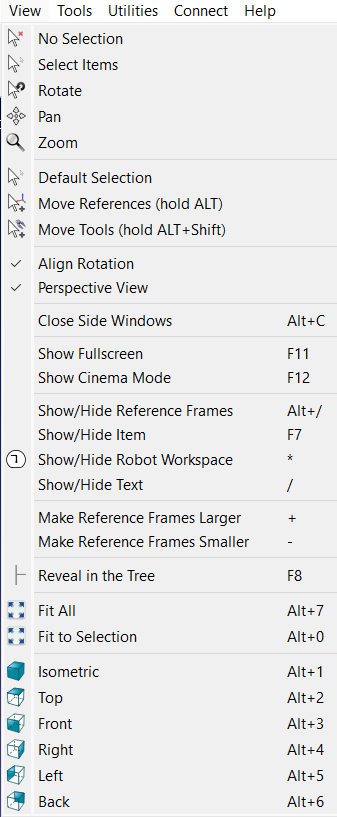
View Menu
Most options required to navigate in 3D are available from the View menu. It is possible to Rotate, Pan and Zoom from this menu (as well as by right clicking the 3D view). This is useful for navigating in 3D using a laptop touchpad (instead of a mouse).
To allow a free rotation in any direction uncheck the option: View➔Align rotation. Otherwise, RoboDK locks the station reference to keep the XY plane horizontal by default.
It is possible to show or hide the robot workspace by selecting the asterisk key (*). It is also possible to switch between visible and invisible items by selecting the F7 key.
Tip: It is possible to make the reference frames bigger or smaller by pressing the + or – key multiple times. If a lot of items are visible this is useful to adjust the size of the reference frames and properly grab them if they need to be moved from the 3D view (by holding the ALT key for example).
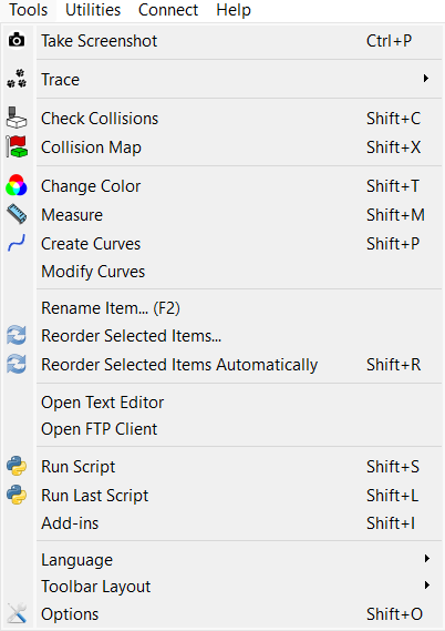
Tools Menu
You can access generic tools in the Tools menu, such as taking 3D measurements, activate collision checking or activating the robot trace.
Activating the Trace will show the trace of all robots as they move.
Check Collisions will activate or deactivate collision checking. When collision checking is activated, objects that are in a collision state will be displayed in red.The Collision Map allows specifying what object interactions are being checked.
Note: More information available regarding collision detection in the Collisions section.
Change Color Tool will display a small window that allows changing the color of robots and objects. It is also possible to flip the normal vectors of surfaces.
Measure will display a window that allows measuring points in 3D with respect to a local reference frame or the station reference frame (absolute measurements).
It is possible to specify the language of the RoboDK application by selecting Tools➔Language and select the preferred language. RoboDK will be displayed in the selected language immediately.
Toolbar Layout allows setting up the default toolbar. Alternatively, it is possible to specify a toolbar for a more basic or more advanced usage.
Select Options to open the main options menu. More information available in the Options Menu section.
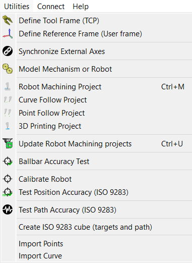
Utilities Menu
The utilities menu allows performing specific tasks to setup your robot and perform specific manufacturing operations such as robot machining, drilling or 3D printing.
Calibrate Tool frame (TCP) allows calibrating a robot TCP by providing data from the real setup, such as the joint configurations to reach a point using different orientations. This procedure is usually available from most robot teach pendants. RoboDK allows calibrating a TCP with as many configurations as desired. Using more configurations allows obtaining a more accurate TCP value. Read more about TCP calibration.
Calibrate Reference Frame allows identifying a reference frame with respect to a robot base frame. This allows accurately matching the part from the real setup to the virtual environment. Read more about Reference Frame calibration.
Synchronize External Axes allows setting up one or more external axes and a robot as one robot mechanism. More information available in the External Axes section.
Robot Machining Project allows you to convert machining toolpaths to robot simulations and robot programs. RoboDK can import programs made for 5-axis CNC using CAM software, such as generic G-code or APT files. These programs/toolpaths can be easily simulated and converted to robot programs with RoboDK. More information available in this section.
The Curve Follow Project is like a Robot Milling project but it allows selecting curves extracted from 3D geometry as toolpaths. It is also possible to select Import Curve to import 3D curves from CSV or TXT files. These curves must be provided as a list of XYZ points and, optionally, IJK vector. More information available in the curve follow project section.
The Point Follow Project is like a Robot Milling project but it allows selecting points extracted from 3D geometry and easily create a robot toolpath. It is also possible to select Import Points to import 3D points from CSV or TXT files. These points must be provided as a list of XYZ points and, optionally, IJK vector. More information available in the point follow project section.
Select 3D print project to generate a robot 3D printing program for a specific object. The object must be available in the RoboDK station. The 3D printing toolpath is converted to G-code behind the scenes using a Slicer and then treated like a 3-axis machining toolpath. More information available in the robot 3D printing section.
The Ballbar Accuracy test allows checking the robot performance using a Telescoping Double Ballbar device. More information about robot ballbar testing available here: https://robodk.com/ballbar-test.
Calibrate Robot allows setting up a robot calibration project to improve robot accuracy and find robot error parameters. A calibrated robot can be used in any RoboDK Offline Programming project. Robot calibration usually improves robot accuracy by a factor of 5 or better, depending on the robot model. Robot calibration requires using measurement systems to take robot measurements. Robot accuracy and repeatability can be tested with ISO9283 before and/or after calibration. More information about robot calibration and performance testing here: https://robodk.com/robot-calibration.
Note: Some of these tools might require a specific license that extends the default offline programming license.
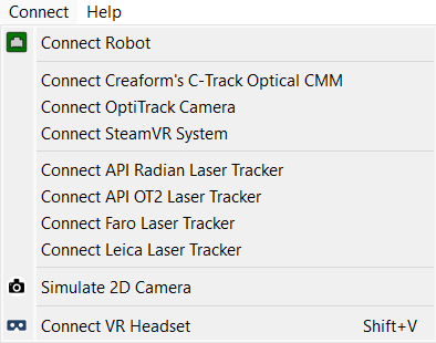
Connect Menu
It is possible to connect to a robot and enter the connections parameters, such as the robot IP, FTP username and FTP password. Setting up a robot connection allows transferring programs through FTP or running programs directly from the PC.
New robot drivers can be developed by end users, more information available in the robot drivers section.
It is also possible to connect to measurement systems such as laser trackers or the Creaform Optical CMM. This allows to fully automate robot calibration and performance testing.
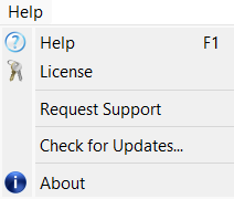
Help Menu
Selecting help in RoboDK opens this documentation online. Also, when you press F1, RoboDK displays the Help topic related to the item currently selected.
Select Check for Updates… to check if an update is available. A message will pop up with a recommended update or just notifying that the current version is already up to date. If no message pops up it means that a firewall is blocking communication between RoboDK and the internet.