Robot Panel
Double click a robot to open the robot panel (you can double click it in the tree or the 3D view). It is possible to jog the robot axes using the Joint axis jog section and enter specific joint axis values in the text boxes. The joint values and the robot coordinates should match with the values displayed by your robot controller.
You can double click the joint limits to modify the robot axis limits. By default, RoboDK uses the same joint limits used by the robot controller (physical hardware limits). Some applications may require more constrained joint limits (software limits). The joint values can be copied 

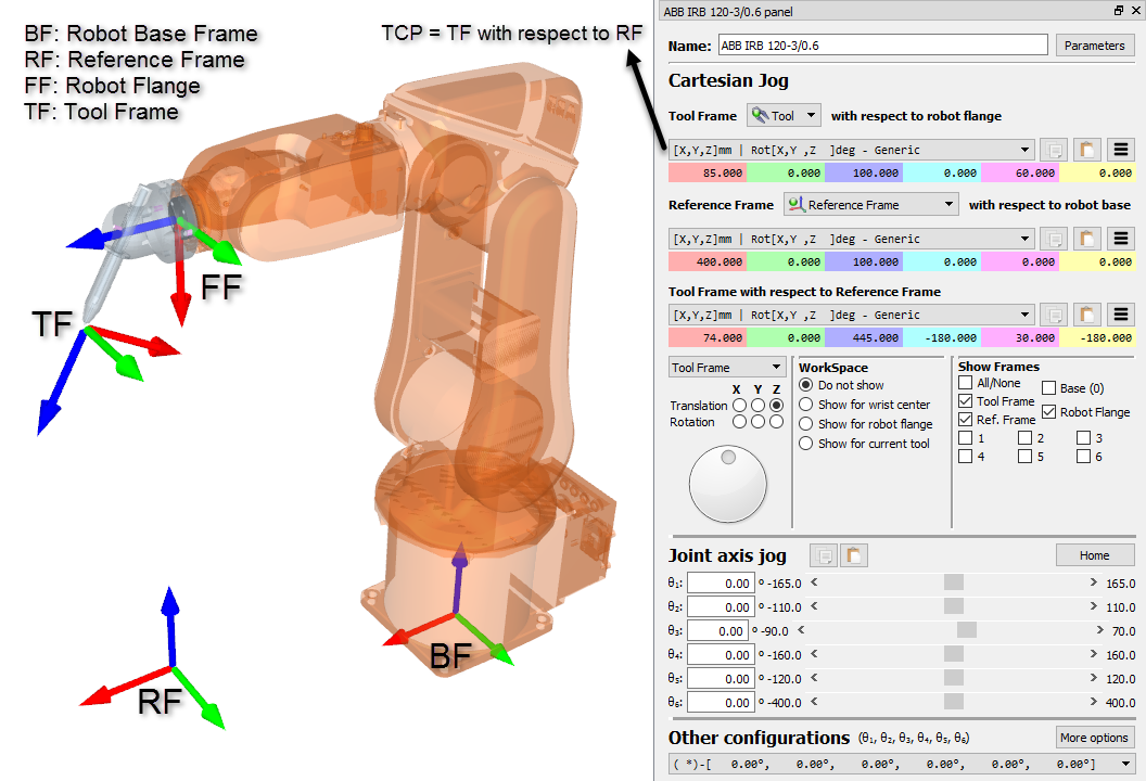
The Cartesian Jog section displays all the information related to the robot kinematics:
●The Tool Frame (TF) with respect to the Robot Flange (FF) defines where the selected Tool Frame is located with respect to the Robot Flange. The Robot Flange is always the same, however, the Tool Frame changes depending on the tool that is mounted on the robot. This relationship is also known as UTOOL, ToolData or just Tool in most robot controllers. The Robot Tool is also known as the TCP (Tool Center Point). The Selected Tool becomes the “Active” tool. The active tool is used when creating new targets and programs. The selected tool displays a green mark in its icon: 
●The Reference Frame (RF) with respect to the Robot Base (BF) defines where the Reference frame is located with respect to Robot Base Frame. The Robot Base Frame never moves, however, different Reference Frames can be used to position any objects with respect to the same Robot Base Frame. This relationship is also known as UFRAME, WorkObject MFRAME or Reference in most robot controllers. The selected reference frame in the robot panel becomes the “Active” reference frame. The active reference frame is used as a reference for new targets and robot programs. The selected reference frame displays a green mark in its icon: 
●The Tool Frame (TF) with respect to the Reference Frame (RF) shows the position of the active TCP with respect to the active reference frame for the current position of the robot. Modify this value to move the robot. The joint axes are recalculated automatically. These Cartesian coordinates are recorded when a new target is created (Program➔Teach Target), together with the robot axes. The target is also attached to the Active reference frame.
A list of possible configurations is available in the Other configurations section. The robot configuration defines a specific state of the robot without crossing any singularities. Changing the configuration requires crossing a singularity. More information available in the Robot Configurations section.
Finally, the Parameters button at the top right allows making some kinematic adjustments, selecting the preferred post processor or extract accurate parameters after a robot calibration project. Modifying these values should only be required in specific circumstances.