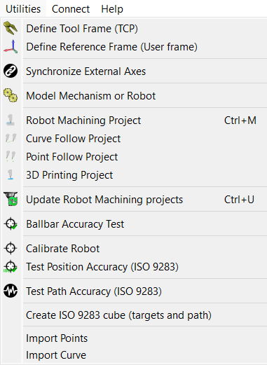
The utilities menu allows performing specific tasks to setup your robot and perform specific manufacturing operations such as robot machining, drilling or 3D printing.
Calibrate Tool frame (TCP) allows calibrating a robot TCP by providing data from the real setup, such as the joint configurations to reach a point using different orientations. This procedure is usually available from most robot teach pendants. RoboDK allows calibrating a TCP with as many configurations as desired. Using more configurations allows obtaining a more accurate TCP value. Read more about TCP calibration.
Calibrate Reference Frame allows identifying a reference frame with respect to a robot base frame. This allows accurately matching the part from the real setup to the virtual environment. Read more about Reference Frame calibration.
Synchronize External Axes allows setting up one or more external axes and a robot as one robot mechanism. More information available in the External Axes section.
Robot Machining Project allows you to convert machining toolpaths to robot simulations and robot programs. RoboDK can import programs made for 5-axis CNC using CAM software, such as generic G-code or APT files. These programs/toolpaths can be easily simulated and converted to robot programs with RoboDK. More information available in this section.
The Curve Follow Project is like a Robot Milling project but it allows selecting curves extracted from 3D geometry as toolpaths. It is also possible to select Import Curve to import 3D curves from CSV or TXT files. These curves must be provided as a list of XYZ points and, optionally, IJK vector. More information available in the curve follow project section.
The Point Follow Project is like a Robot Milling project but it allows selecting points extracted from 3D geometry and easily create a robot toolpath. It is also possible to select Import Points to import 3D points from CSV or TXT files. These points must be provided as a list of XYZ points and, optionally, IJK vector. More information available in the point follow project section.
Select 3D print project to generate a robot 3D printing program for a specific object. The object must be available in the RoboDK station. The 3D printing toolpath is converted to G-code behind the scenes using a Slicer and then treated like a 3-axis machining toolpath. More information available in the robot 3D printing section.
The Ballbar Accuracy test allows checking the robot performance using a Telescoping Double Ballbar device. More information about robot ballbar testing available here: https://robodk.com/ballbar-test.
Calibrate Robot allows setting up a robot calibration project to improve robot accuracy and find robot error parameters. A calibrated robot can be used in any RoboDK Offline Programming project. Robot calibration usually improves robot accuracy by a factor of 5 or better, depending on the robot model. Robot calibration requires using measurement systems to take robot measurements. Robot accuracy and repeatability can be tested with ISO9283 before and/or after calibration. More information about robot calibration and performance testing here: https://robodk.com/robot-calibration.
Note: Some of these tools might require a specific license that extends the default offline programming license.