Display tab
The display tab allows you to customize settings related to the appearance of the 3D view.
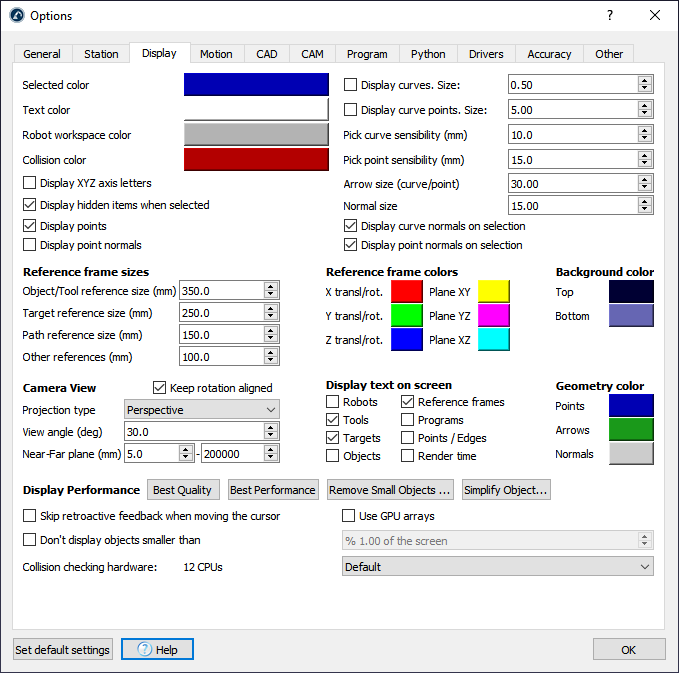
Select the colored button beside the Selected color, Text color, Workspace or Collision color to change the default colors used in the 3D view.
Select Display XYZ axes letters to display the reference frames with the corresponding X, Y, Z letters. By default, they are not displayed and the Red (X), Green (Y) and Blue (Z) colors are used respectively.
Increase the Pick curve/point sensibility to make it easier to select curves and points respectively. Alternatively, if curves or points are too close to each other and it is not easy to select them it is better to reduce these values.
Arrow size (curve/point) is the size of the green arrows displayed in curve or point follow projects (available from the Utilities menu).
Object/Target/Path/Other reference size will define the size of the frames on the screen for specific items. It is recommended to use the keys + and – instead to grow or shrink the sizes proportionally.
The reference frame colors can be updated as well as the gradient background colors manually (the plane colors are displayed when moving reference frames with the mouse).
The Camera view is set to Perspective by default. It is possible to change it to Orthographic and update some camera settings such as the View angle and the Near/Far planes.
Uncheck Keep rotation aligned to freely rotate in any direction.
By default, the display settings are set to obtain the Best Quality results. Set the Display Performance to Best Performance if RoboDK slows down because there are too many objects being displayed. This will force using the GUP and not display small objects in the screen.
It is also possible to display RoboDK on a 3D screen (use 3D view for Virtual Reality). The Stereo camera distance will define how close or far the objects feel.