Examples
This section shows basic examples to load a Rhino project in RoboDK for robot simulation and offline programming purposes.
Engraving a dome
Dome stripes
This example shows how to load a sample RoboDK station (default setup) and follow a set of curves defined in Rhino with the robot.
1.Load the Dome example in Rhino.
2.Select the RoboDK tab and select 
3.Select Load Project…
4.Select Default Setup. RoboDK will start and load a sample project with a KUKA robot, one tool (a spindle as Tool 1) and one reference frame (Reference 1).
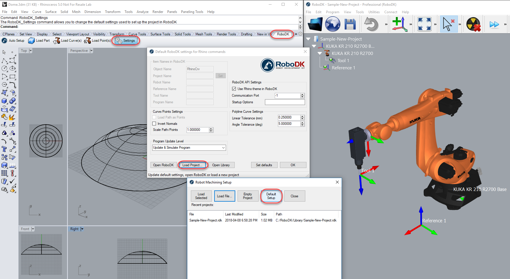
5.Close the Settings window or select OK.
6.Select the 
7.Select all the curves and surfaces and press Enter (or right mouse click). The project will be loaded in RoboDK as shown in the following image.
You should see the part loaded on the active reference frame (Reference 1) and a new Curve follow project in RoboDK that follows the curves with the active robot tool (Tool 1).
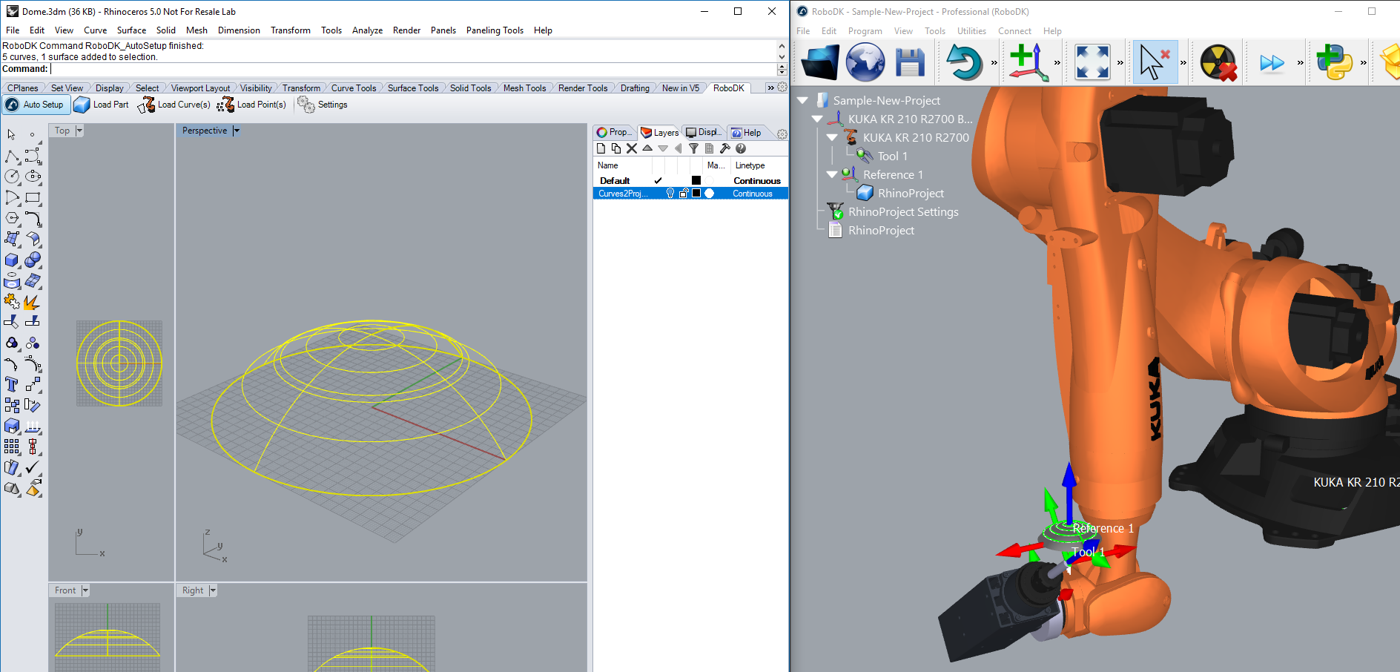
You can also see that the surface normals have been extracted in the opposite direction. Follow these steps to solve this issue:
8.Select
9.Check the option Invert Normals.
10.Select OK.
11.Repeat steps 6 and 7.
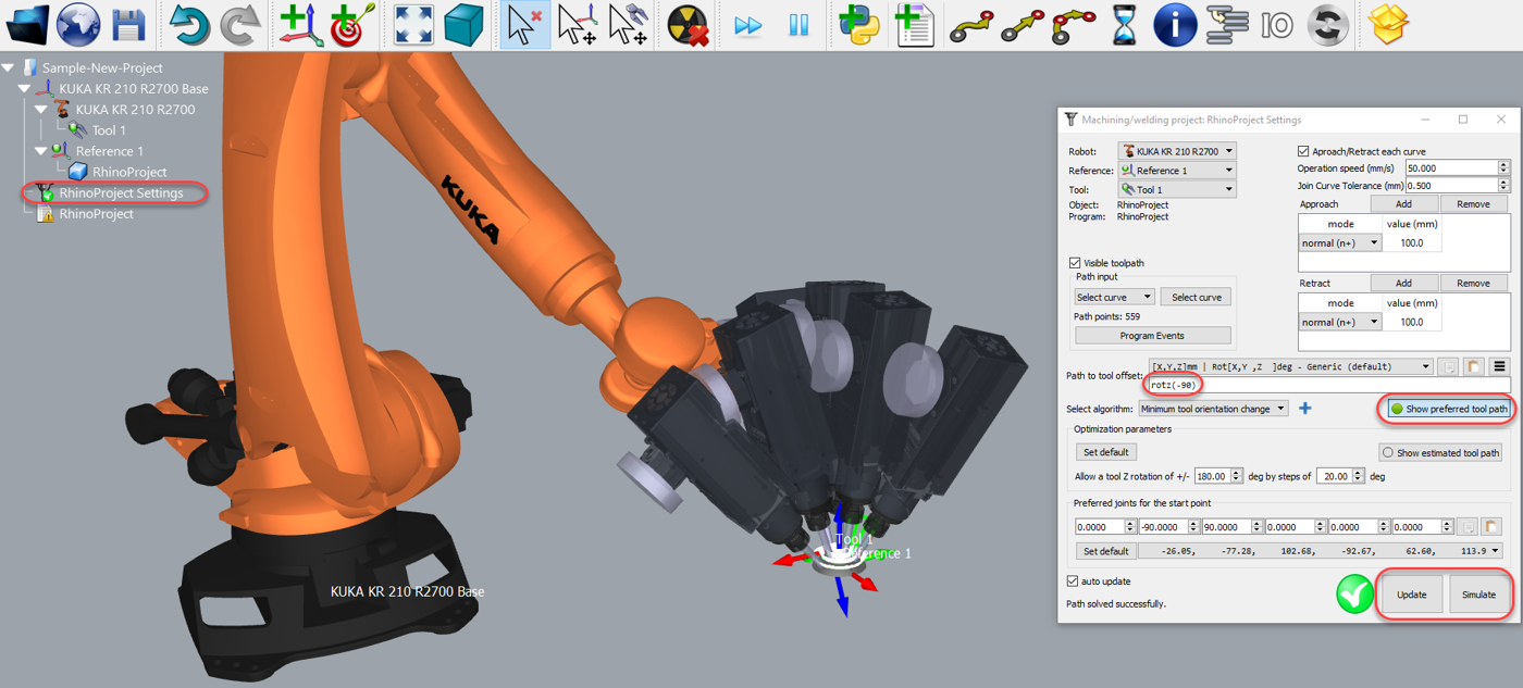
You should now see the surface normals flipped and the approach movement comes from the top of the part. The robot should be able to move along the toolpath without any issues.
Double click the 
For example, you can select Show preferred tool path to see and modify the default orientation of the tool with respect to the part. Change the Path to tool offset value to define an additional rotation. To do so, you can enter a new value or just use the mouse wheel to see a quick preview of the result.
More information to change these settings is available in the robot machining section.
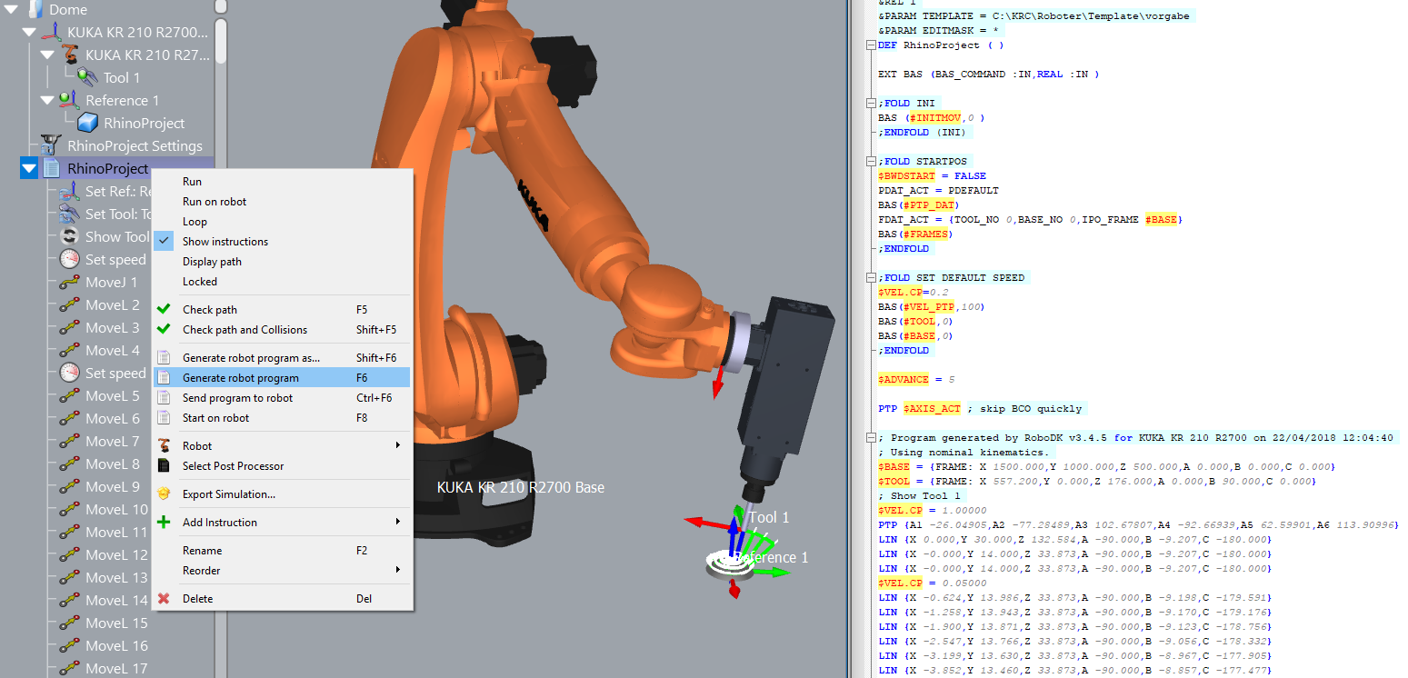
Finally, when the simulation produces the desired result you can generate the program or export the simulation:
12.Right click the program RhinoProject
13.Select Generate robot program (F6). The robot program will be generated and displayed.
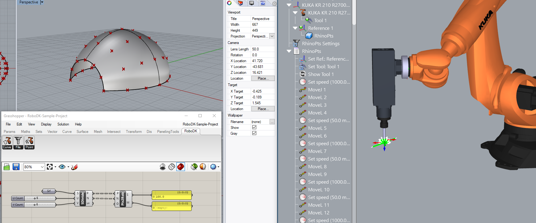
Grasshopper Example
This example shows how to use the RoboDK plug-in for Grasshopper by dividing a surface as a grid of points and following them with a robot for a drilling operation in RoboDK:
1.Load the Grasshopper example provided with the RoboDK plug-in (3dm file and gh file).
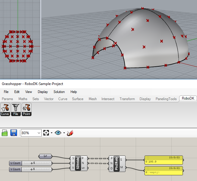
2.Right click the Pts2Rob component and select Robot Setup Options (RoboDK). Select Load Project… and select Default Setup to load a sample RoboDK station (same sample project shown in the previous section).
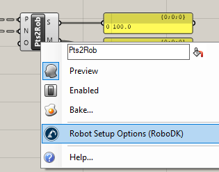
You can optionally provide the object name as a component input (O). You can also specify a project in the component options so that the desired RoboDK project is used with each component.
3.In Grasshopper, select Solution➔Recompute (F5) to update the part and the program in RoboDK.