Settings
You can change the default settings that apply to the RoboDK plug-in by selecting the Settings button.
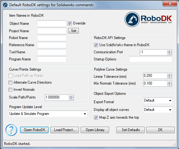
●Object Name – Set the name of the curve/points object that will be loaded in RoboDK. If this case is left blank, the name of the part or the assembly file will be used.
●Override – Override the object loaded previously in RoboDK if there is a name match.
●Project Name – Set the name/path of the RoboDK project/station (.RDK file) to use. If the file is already loaded it will use the existing project. If the open project in RoboDK does not match with the file name, it will open the project if the full path is specified.
●Robot Name – Set the name of the robot that will be used in RoboDK (if you have more than 1 robot in your project). The robot name must match the name visible in the RoboDK station tree. Leave this value empty (default) to use the first or only robot available.
●Reference Name – Set the name of the reference frame to place the path with respect to the robot. The name should match the visible name in the RoboDK station tree. If a name is not provided, the active Reference Frame
●Tool Name – Set the name of the tool (TCP) to use with the robot to follow the path. The name should match the visible name in the RoboDK station tree. If a name is not provided, the active Tool Frame
●Program Name – Set the name of the program file that will be generated.
●Load Path as Points – Check this option to convert a curve into points, so a Point follow projectwill be created in RoboDK. This is useful for manufacturing operations such as drilling. Uncheck this option to load the path as a Curve follow project.
●Alternate Curve Directions - Check this option to alternate the direction of movement with each pass (Zig-Zag pattern).
●Invert Normals – Check this option to invert the calculated surface normals. This will flip the robot’s tool orientation.
●Use SolidWorks Theme in RoboDK – Start RoboDK with a SolidWorks theme. This includes changing the behavior of the mouse for 3D navigation and the background color. These settings can be changed in the RoboDK menu Tools-Options.
●Communication Port – Set the communication port to communicate with RoboDK. Multiple instances of RoboDK can be running at the same time and use different setups if a different port is used. When this value is set to -1 (default), the default port is used (20500).
●Startup Options – Set the arguments to pass to RoboDK the first time it starts. For example, to start RoboDK quietly you can set '/NOSPLASH /NOSHOW /HIDDEN'. Programs can still be generated even if RoboDK is not displayed. More information in the Command Line section of the RoboDK API.
●Linear Tolerance (mm) – Set the linear accuracy to split curves as a set of points.
●Mix Normals Tolerance (mm) – Set the distance tolerance used to mix normal calculations among multiple surfaces.
●Export Format – Select the export format to load the part in RoboDK.
●Display all object curves – Display the curves loaded in RoboDK even if they are not selected. You can change this setting in RoboDK (Tools-Options-Display-Display Curves).
●Map Z axis towards the top – Apply a rotation to the part or the assembly to match the Z axis in RoboDK. This makes sure that the isometric view in RoboDK is the same as in SolidWorks.
Buttons:
●Open RoboDK – Open a project in RoboDK... A new window will open with additional options.
●Load Project … – Load the RoboDK project (RDK file) that you want to use for your current project.
●Open Library – Open RoboDK's online library.
●Set Defaults – Set the default settings for the component.
●OK – Apply these settings and close this window. Not selecting OK will not apply any settings you changed.