RoboDK Add-In for SolidWorks
The RoboDK add-in for SolidWorks allows you to combine SolidWork’s 3D CAD modeling features with RoboDK for robot simulation and offline programming.
With the RoboDK plug-in for SolidWorks you can easily load 3D models created in SolidWorks to RoboDK. This plug-in allows you to program any robot supported by RoboDK directly from SolidWorks.
Robot programs can be generated directly from a group of curves or points. You can also create an NC program such as G-code or an APT file and load it in RoboDK.
Robots can be easily programmed as 5-axis machines for a wide variety of manufacturing applications such as drilling, welding, trimming, 3D printing or robot machining. More information available in the robot machining section.
The robot post processors section shows a list of the robot brands and controllers supported. It is also possible to modify or create new post processors to customize program generation.
The RoboDK plug-in for SolidWorks works for SolidWorks 2016 and later. The RoboDK SolidWorks plug-in is free, however, certain options in RoboDK require purchasing a license.
Install
If you have already installed SolidWorks and RoboDK you should have the RoboDK plug-in for SolidWorks available from Solidworks.
The RoboDK plug-in for SolidWorks contains a Toolbar. Each button of the toolbar is linked to a RoboDK command.
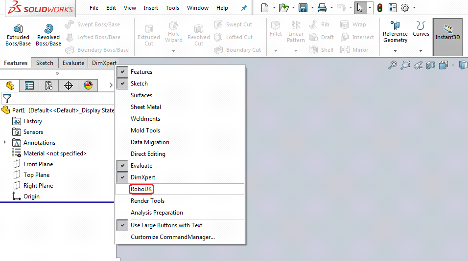
If the RoboDK plug-in is not available, you can follow the manual installation steps to install the RoboDK plug-in for SolidWorks.
SolidWorks Toolbar
The default RoboDK toolbar includes 5 buttons:
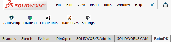
●
●
●
●
●
The main difference between Auto Setup and Load Curve(s) or Load Point(s) is that Auto Setup loads the part and creates a new Curve/Point follow project. Using Load Curve(s) or Load Point(s) is faster and will just update the existing geometry features in RoboDK, keeping previously defined settings.
Settings
You can change the default settings that apply to the RoboDK plug-in by selecting the Settings button.
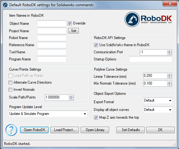
●Object Name – Set the name of the curve/points object that will be loaded in RoboDK. If this case is left blank, the name of the part or the assembly file will be used.
●Override – Override the object loaded previously in RoboDK if there is a name match.
●Project Name – Set the name/path of the RoboDK project/station (.RDK file) to use. If the file is already loaded it will use the existing project. If the open project in RoboDK does not match with the file name, it will open the project if the full path is specified.
●Robot Name – Set the name of the robot that will be used in RoboDK (if you have more than 1 robot in your project). The robot name must match the name visible in the RoboDK station tree. Leave this value empty (default) to use the first or only robot available.
●Reference Name – Set the name of the reference frame to place the path with respect to the robot. The name should match the visible name in the RoboDK station tree. If a name is not provided, the active Reference Frame
●Tool Name – Set the name of the tool (TCP) to use with the robot to follow the path. The name should match the visible name in the RoboDK station tree. If a name is not provided, the active Tool Frame
●Program Name – Set the name of the program file that will be generated.
●Load Path as Points – Check this option to convert a curve into points, so a Point follow projectwill be created in RoboDK. This is useful for manufacturing operations such as drilling. Uncheck this option to load the path as a Curve follow project.
●Alternate Curve Directions - Check this option to alternate the direction of movement with each pass (Zig-Zag pattern).
●Invert Normals – Check this option to invert the calculated surface normals. This will flip the robot’s tool orientation.
●Use SolidWorks Theme in RoboDK – Start RoboDK with a SolidWorks theme. This includes changing the behavior of the mouse for 3D navigation and the background color. These settings can be changed in the RoboDK menu Tools-Options.
●Communication Port – Set the communication port to communicate with RoboDK. Multiple instances of RoboDK can be running at the same time and use different setups if a different port is used. When this value is set to -1 (default), the default port is used (20500).
●Startup Options – Set the arguments to pass to RoboDK the first time it starts. For example, to start RoboDK quietly you can set '/NOSPLASH /NOSHOW /HIDDEN'. Programs can still be generated even if RoboDK is not displayed. More information in the Command Line section of the RoboDK API.
●Linear Tolerance (mm) – Set the linear accuracy to split curves as a set of points.
●Mix Normals Tolerance (mm) – Set the distance tolerance used to mix normal calculations among multiple surfaces.
●Export Format – Select the export format to load the part in RoboDK.
●Display all object curves – Display the curves loaded in RoboDK even if they are not selected. You can change this setting in RoboDK (Tools-Options-Display-Display Curves).
●Map Z axis towards the top – Apply a rotation to the part or the assembly to match the Z axis in RoboDK. This makes sure that the isometric view in RoboDK is the same as in SolidWorks.
Buttons:
●Open RoboDK – Open a project in RoboDK... A new window will open with additional options.
●Load Project … – Load the RoboDK project (RDK file) that you want to use for your current project.
●Open Library – Open RoboDK's online library.
●Set Defaults – Set the default settings for the component.
●OK – Apply these settings and close this window. Not selecting OK will not apply any settings you changed.
Examples
This section shows basic examples to load a SolidWorks project in RoboDK for robot simulation and offline programming purposes.
Robot Welding
The following example shows how you can create a simple toolpath for robot welding from SolidWorks.
Liquid dispensing
The following example shows how you can program a robot for a liquid dispensing application using SolidWorks and RoboDK.
Propeller Example
This example shows how to load a sample RoboDK station (default setup) and follow a set of curves defined in SolidWorks with the robot.
1.Load the 3 bladed Propellers example in SolidWorks.
2.Select the RoboDK tab and select
3.Select Load Project…
4.Select Default Setup. RoboDK will start and load a sample project with a KUKA robot, one tool (a spindle as Tool 1) and one reference frame (Reference 1).
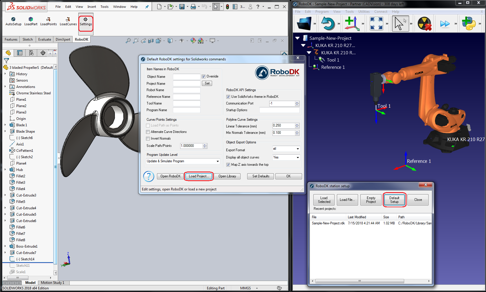
5.Close the Settings window or select OK.
6.Select the
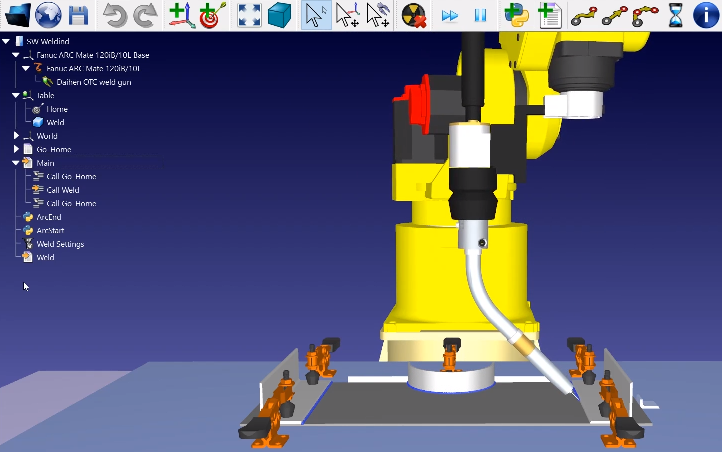
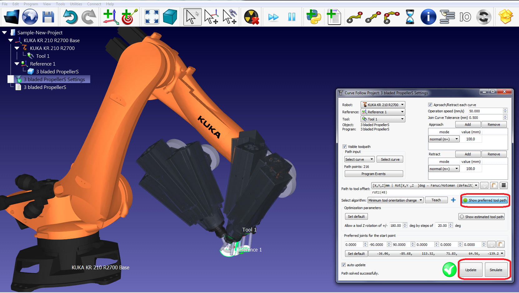
7.Select all the curves and surfaces and press OK in Property Manager Page. The project will be loaded in RoboDK as shown in the following image.
You should see the part loaded on the active reference frame (Reference 1) and a new Curve follow project in RoboDK that follows the toolpath.
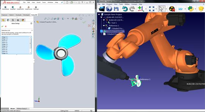
You can see the approach movement is normal to the toolpath. The robot should be able to move along the toolpath without any issues.
Double click the 
For example, you can select Show preferred tool path to see and modify the default orientation of the tool with respect to the part. Change the Path to tool offset value to define an additional rotation. To do so, you can enter a new value or just use the mouse wheel to see a quick preview of the result.
More information to change these settings is available in the robot machining section.
Finally, when the simulation produces the desired result, you can generate the program or export the simulation:
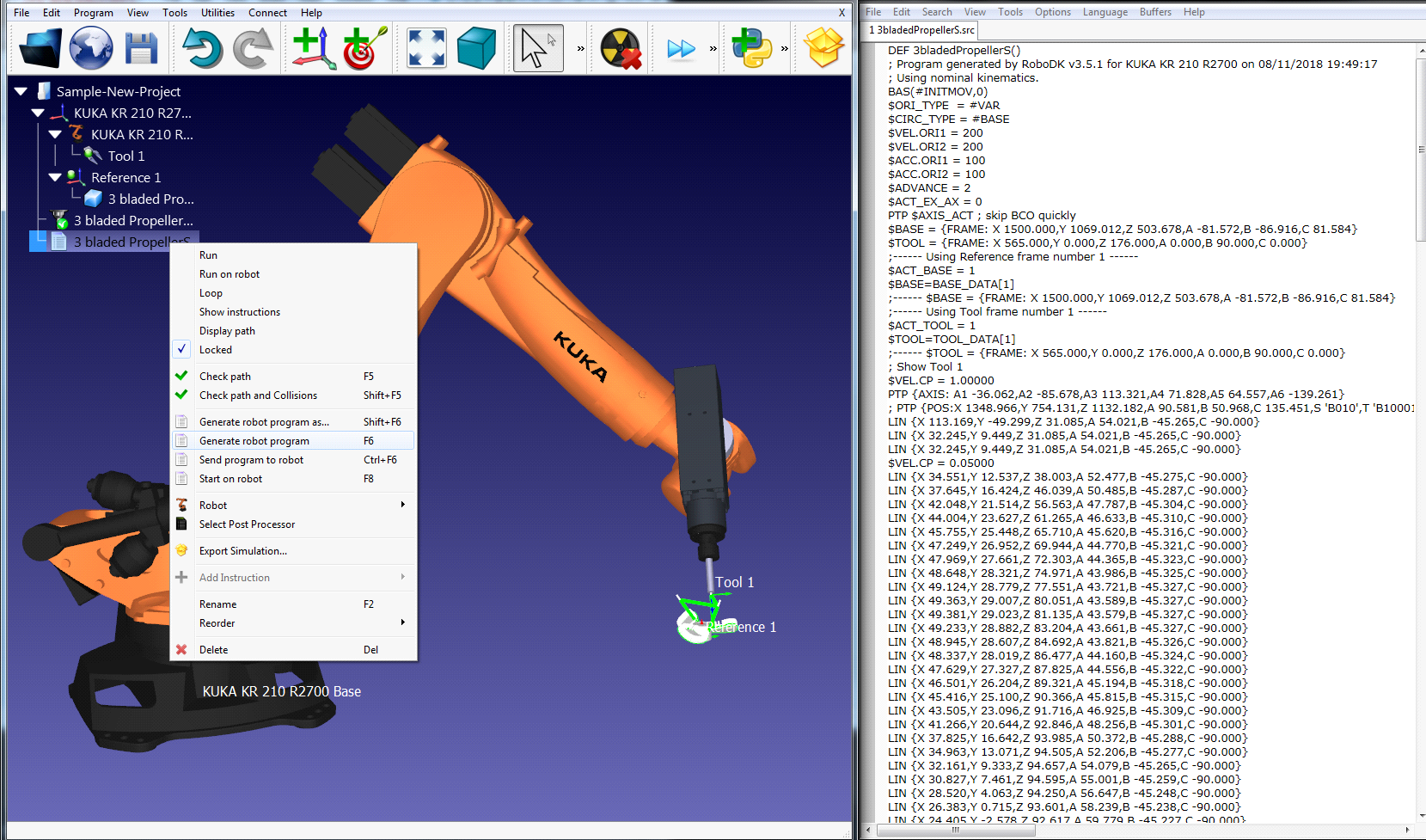
8.Right click the program
9.Select Generate robot program (F6). The robot program will be generated and displayed.
Manual Install
These are manual steps to setup the RoboDK plug-in for SolidWorks. You should follow these steps if the RoboDK plug-in for SolidWorks was not automatically installed by default using the RoboDK installer:
1.Install SolidWorks.
2.Download and install RoboDK.
3.Download the RoboDK plugin for SolidWorks.
4.Unzip the RoboDK plug-in for SolidWorks folder in C:\RoboDK\Other\Plugin-SolidWorks\
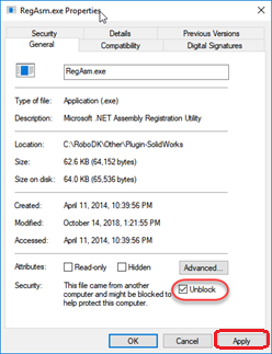
Unblock the EXE and DLL binaries:
5.Right click the file RegAsm.exe and select Properties.
6.Select Unblock and Apply.
7.Repeat steps 5 and 6 for the other two DLL files.
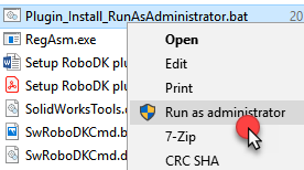
Load the RoboDK plug-in in SolidWorks:
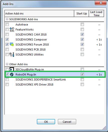
8.Run the Plugin_Install_RunAsAdministrator.bat file as Administrator: Right click the BAT file and select Run as Administrator.
9.Start SolidWorks and go to Tools➔Add-Ins (in SolidWorks). You’ll find find the RoboDK Plug-In Addin.