6. Examples
This section shows some examples in Python that use the RoboDK API. Most of these examples can be easily ported to other programming languages (such as C#, C++, .Net or Matlab). These examples were tested using Python 3 and might require some adjustments to work on Python 2.
Additional RoboDK API examples are included in the following folders:
C:/RoboDK/Library/Scripts/
C:/RoboDK/Library/Macros/
Any Python files available in the Scripts folder can be run as a standalone script by selecting:
Tools-Run Script
Select the script to run it
Many RoboDK Add-ins have been created using Python and they are not compiled so you can also use them as examples: https://robodk.com/addins.
Some examples are used in sample RoboDK projects (RDK files) provided in the RoboDK library. Some examples are also available on GitHub: https://github.com/RoboDK/RoboDK-API/tree/master/Python/Examples.
6.1. Offline Programming
This example shows how to generate a hexagonal path given one target. This macro draws a polygon of radius R and n_sides vertices using the RoboDK API for Python.
- More information here:
Offline Programming with RoboDK: https://robodk.com/offline-programming
Simulation using the RoboDK API for Python: https://robodk.com/doc/en/RoboDK-API.html#PythonAPIOLP
Post processors: https://robodk.com/doc/en/Post-Processors.html#PostProcessor
Offline programming overview: https://www.youtube.com/watch?list=PLjiA6TvRACQc5E_3c5f3TFXEa56XNR1-m&v=Ic-iKGSc7dk
# This macro shows an example to draw a polygon of radius R and n_sides vertices using the RoboDK API for Python
# More information about the RoboDK API here:
# https://robodk.com/doc/en/RoboDK-API.html
from robodk.robolink import *  # API to communicate with RoboDK
from robodk.robomath import *  # basic matrix operations

# Any interaction with RoboDK must be done through RDK:
RDK = Robolink()

# Select a robot (popup is displayed if more than one robot is available)
robot = RDK.ItemUserPick('Select a robot', ITEM_TYPE_ROBOT)
if not robot.Valid():
    raise Exception('No robot selected or available')

# get the current position of the TCP with respect to the reference frame:
# (4x4 matrix representing position and orientation)
target_ref = robot.Pose()
pos_ref = target_ref.Pos()
print("Drawing a polygon around the target: ")
print(Pose_2_TxyzRxyz(target_ref))

# move the robot to the first point:
robot.MoveJ(target_ref)

# It is important to provide the reference frame and the tool frames when generating programs offline
robot.setPoseFrame(robot.PoseFrame())
robot.setPoseTool(robot.PoseTool())
robot.setRounding(10)  # Set the rounding parameter (Also known as: CNT, APO/C_DIS, ZoneData, Blending radius, cornering, ...)
robot.setSpeed(200)  # Set linear speed in mm/s

# Set the number of sides of the polygon:
n_sides = 6
R = 100

# make a hexagon around reference target:
for i in range(n_sides + 1):
    ang = i * 2 * pi / n_sides  #angle: 0, 60, 120, ...

    #-----------------------------
    # Movement relative to the reference frame
    # Create a copy of the target
    target_i = Mat(target_ref)
    pos_i = target_i.Pos()
    pos_i[0] = pos_i[0] + R * cos(ang)
    pos_i[1] = pos_i[1] + R * sin(ang)
    target_i.setPos(pos_i)
    print("Moving to target %i: angle %.1f" % (i, ang * 180 / pi))
    print(str(Pose_2_TxyzRxyz(target_i)))
    robot.MoveL(target_i)

    #-----------------------------
    # Post multiply: relative to the tool
    #target_i = target_ref * rotz(ang) * transl(R,0,0) * rotz(-ang)
    #robot.MoveL(target_i)

# move back to the center, then home:
robot.MoveL(target_ref)

print('Done')
6.2. Offline Programming (GUI)
This example is an improved version of the previous example. It prompts the user for some input before simulating or generating a program. This example shows how RoboDK and the Python GUI tkinter can display graphical user interface to customize program generation according to certain parameters.
- More information here:
Simulation using the RoboDK API for Python: https://robodk.com/doc/en/RoboDK-API.html#PythonAPIOLP
Post processors: https://robodk.com/doc/en/Post-Processors.html#PostProcessor
# This example shows how RoboDK and the Python GUI tkinter can display graphical user interface to customize program generation according to certain parameters
# This example is an improvement of the weld Hexagon
# More information about the RoboDK API here:
# https://robodk.com/doc/en/RoboDK-API.html
from robodk.robolink import *  # API to communicate with RoboDK
from robodk.robomath import *  # robodk robotics toolbox

# Set up default parameters
PROGRAM_NAME = "DoWeld"  # Name of the program
APPROACH = 300  # Approach distance
RADIUS = 200  # Radius of the polygon
SPEED_WELD = 50  # Speed in mn/s of the welding path
SPEED_MOVE = 200  # Speed in mm/s of the approach/retract movements
SIDES = 8  # Number of sides for the polygon
DRY_RUN = 1  # If 0, it will generate SprayOn/SprayOff program calls, otherwise it will not activate the tool
RUN_MODE = RUNMODE_SIMULATE  # Simulation behavior (simulate, generate program or generate the program and send it to the robot)

# use RUNMODE_SIMULATE to simulate only
# use RUNMODE_MAKE_ROBOTPROG to generate the program
# use RUNMODE_MAKE_ROBOTPROG_AND_UPLOAD to generate the program and send it to the robot


# Main program
def RunProgram():
    # Use default global variables
    global PROGRAM_NAME
    global APPROACH
    global RADIUS
    global SPEED_WELD
    global SPEED_MOVE
    global SIDES
    global DRY_RUN
    global RUN_MODE

    # Any interaction with RoboDK must be done through RDK:
    RDK = Robolink()

    # get the home target and the welding targets:
    home = RDK.Item('Home')
    target = RDK.Item('Target Reference')

    # get the robot as an item:
    robot = RDK.Item('', ITEM_TYPE_ROBOT)

    # impose the run mode
    RDK.setRunMode(RUN_MODE)
    # set the name of the generated program
    RDK.ProgramStart(PROGRAM_NAME, "", "", robot)

    # get the pose of the reference target (4x4 matrix representing position and orientation):
    poseref = target.Pose()

    # move the robot to home, then to an approach position
    robot.MoveJ(home)
    robot.setSpeed(SPEED_MOVE)
    robot.MoveJ(transl(0, 0, APPROACH) * poseref)

    # make an polygon of n SIDES around the reference target
    for i in range(SIDES + 1):
        ang = i * 2 * pi / SIDES  #angle: 0, 60, 120, ...
        # Calculate next position
        posei = poseref * rotz(ang) * transl(RADIUS, 0, 0) * rotz(-ang)
        robot.MoveL(posei)

        # Impose weld speed only for the first point
        if i == 0:
            # Set weld speed and activate the gun after reaching the first point
            robot.setSpeed(SPEED_WELD)
            if not DRY_RUN:
                # Activate the spray right after we reached the first point
                robot.RunCodeCustom("SprayOn", INSTRUCTION_CALL_PROGRAM)

    # Stop the tool if we are not doing a dry run
    if not DRY_RUN:
        robot.RunCodeCustom("SprayOff", INSTRUCTION_CALL_PROGRAM)
    robot.setSpeed(SPEED_MOVE)

    # move back to the approach point, then home:
    robot.MoveL(transl(0, 0, APPROACH) * poseref)
    robot.MoveJ(home)

    # Provoke program generation (automatic when RDK is finished)
    RDK.Finish()


# Use tkinter to display GUI menus
from tkinter import *

# Generate the main window
root = Tk()
root.title("Program settings")

# Use variables linked to the global variables
runmode = IntVar()
runmode.set(RUN_MODE)  # setting up default value

dryrun = IntVar()
dryrun.set(DRY_RUN)  # setting up default value

entry_name = StringVar()
entry_name.set(PROGRAM_NAME)

entry_speed = StringVar()
entry_speed.set(str(SPEED_WELD))


# Define feedback call
def ShowRunMode():
    print("Selected run mode: " + str(runmode.get()))


# Define a label and entry text for the program name
Label(root, text="Program name").pack()
Entry(root, textvariable=entry_name).pack()

# Define a label and entry text for the weld speed
Label(root, text="Weld speed (mm/s)").pack()
Entry(root, textvariable=entry_speed).pack()

# Define a check box to do a dry run
Checkbutton(root, text="Dry run", variable=dryrun, onvalue=1, offvalue=0, height=5, width=20).pack()

# Add a display label for the run mode
Label(root, text="Run mode", justify=LEFT, padx=20).pack()

# Set up the run modes (radio buttons)
runmodes = [("Simulate", RUNMODE_SIMULATE), ("Generate program", RUNMODE_MAKE_ROBOTPROG), ("Send program to robot", RUNMODE_MAKE_ROBOTPROG_AND_START)]
for txt, val in runmodes:
    Radiobutton(root, text=txt, padx=20, variable=runmode, command=ShowRunMode, value=val).pack(anchor=W)


# Add a button and default action to execute the current choice of the user
def ExecuteChoice():
    global DRY_RUN
    global RUN_MODE
    global SPEED_WELD
    global PROGRAM_NAME
    DRY_RUN = dryrun.get()
    RUN_MODE = runmode.get()
    SPEED_WELD = float(entry_speed.get())
    PROGRAM_NAME = entry_name.get()
    # Run the main program once all the global variables have been set
    RunProgram()


Button(root, text='Simulate/Generate', command=ExecuteChoice).pack()

# Important to display the graphical user interface
root.mainloop()
6.3. Online Programming
This example is a modified version of the previous two examples which supports running the program on the robot directly from the script. This example will run a Python program on the robot from the Python API (online programming). If a robot is connected to the PC, the simulation and the real robot will move at the same time as the Python program is executed. The same program can also be used for simulation or offline programming.
- More information here:
Online programming using the RoboDK API for Python: https://robodk.com/doc/en/RoboDK-API.html#PythonAPIOnline
Robot drivers: https://robodk.com/doc/en/Robot-Drivers.html#RobotDrivers
# This macro shows an example to run a program on the robot from the Python API (online programming)
#
# Important: By default, right clicking a program on the RoboDK API and selecting "Run On Robot" has the same effect as running this example.
# Use the Example_OnlineProgramming.py instead if the program is run from the RoboDK Station Tree
#
# This example forces the connection to the robot by using:
# robot.Connect()
# and
# RDK.setRunMode(RUNMODE_RUN_ROBOT)

# In this script, if the variable RUN_ON_ROBOT is set to True, an attempt will be made to connect to the robot
# Alternatively, if the RUN_ON_ROBOT variable is set to False, the program will be simulated (offline programming)
#
# More information about the RoboDK API here:
# https://robodk.com/doc/en/RoboDK-API.html

from robodk.robolink import *  # API to communicate with RoboDK
from robodk.robomath import *  # basic matrix operations

# Any interaction with RoboDK must be done through RDK:
RDK = Robolink()

# Select a robot (popup is displayed if more than one robot is available)
robot = RDK.ItemUserPick('Select a robot', ITEM_TYPE_ROBOT)
if not robot.Valid():
    raise Exception('No robot selected or available')

RUN_ON_ROBOT = True

# Important: by default, the run mode is RUNMODE_SIMULATE
# If the program is generated offline manually the runmode will be RUNMODE_MAKE_ROBOTPROG,
# Therefore, we should not run the program on the robot
if RDK.RunMode() != RUNMODE_SIMULATE:
    RUN_ON_ROBOT = False

if RUN_ON_ROBOT:
    # Update connection parameters if required:
    # robot.setConnectionParams('192.168.2.35',30000,'/', 'anonymous','')

    # Connect to the robot using default IP
    success = robot.Connect()  # Try to connect once
    #success robot.ConnectSafe() # Try to connect multiple times
    status, status_msg = robot.ConnectedState()
    if status != ROBOTCOM_READY:
        # Stop if the connection did not succeed
        print(status_msg)
        raise Exception("Failed to connect: " + status_msg)

    # This will set to run the API programs on the robot and the simulator (online programming)
    RDK.setRunMode(RUNMODE_RUN_ROBOT)
    # Note: This is set automatically when we Connect() to the robot through the API

#else:
# This will run the API program on the simulator (offline programming)
# RDK.setRunMode(RUNMODE_SIMULATE)
# Note: This is the default setting if we do not execute robot.Connect()
# We should not set the RUNMODE_SIMULATE if we want to be able to generate the robot programm offline

# Get the current joint position of the robot
# (updates the position on the robot simulator)
joints_ref = robot.Joints()

# get the current position of the TCP with respect to the reference frame:
# (4x4 matrix representing position and orientation)
target_ref = robot.Pose()
pos_ref = target_ref.Pos()
print("Drawing a polygon around the target: ")
print(Pose_2_TxyzRxyz(target_ref))

# move the robot to the first point:
robot.MoveJ(target_ref)

# It is important to provide the reference frame and the tool frames when generating programs offline
# It is important to update the TCP on the robot mostly when using the driver
robot.setPoseFrame(robot.PoseFrame())
robot.setPoseTool(robot.PoseTool())
robot.setRounding(10)  # Set the rounding parameter (Also known as: CNT, APO/C_DIS, ZoneData, Blending radius, cornering, ...)
robot.setSpeed(200)  # Set linear speed in mm/s

# Set the number of sides of the polygon:
n_sides = 6
R = 100

# make a hexagon around reference target:
for i in range(n_sides + 1):
    ang = i * 2 * pi / n_sides  #angle: 0, 60, 120, ...

    #-----------------------------
    # Movement relative to the reference frame
    # Create a copy of the target
    target_i = Mat(target_ref)
    pos_i = target_i.Pos()
    pos_i[0] = pos_i[0] + R * cos(ang)
    pos_i[1] = pos_i[1] + R * sin(ang)
    target_i.setPos(pos_i)
    print("Moving to target %i: angle %.1f" % (i, ang * 180 / pi))
    print(str(Pose_2_TxyzRxyz(target_i)))
    robot.MoveL(target_i)

    #-----------------------------
    # Post multiply: relative to the tool
    #target_i = target_ref * rotz(ang) * transl(R,0,0) * rotz(-ang)
    #robot.MoveL(target_i)

# move back to the center, then home:
robot.MoveL(target_ref)

print('Done')

## Example to run a program created using the GUI from the API
#prog = RDK.Item('MainProgram', ITEM_TYPE_PROGRAM)
## prog.setRunType(PROGRAM_RUN_ON_ROBOT) # Run on robot option
## prog.setRunType(PROGRAM_RUN_ON_SIMULATOR) # Run on simulator (default on startup)
#prog.RunProgram()
#while prog.Busy() == 1:
#    pause(0.1)
#print("Program done")
6.4. Points to Program
This example shows different ways of moving a robot along a list of points.
# Move a robot along a line given a start and end point by steps
# This macro shows three different ways of programming a robot using a Python script and the RoboDK API

# More information about the RoboDK API here:
# https://robodk.com/doc/en/RoboDK-API.html
# For more information visit:
# https://robodk.com/doc/en/PythonAPI/robodk.html#robolink-py

# Default parameters:
P_START = [1755, -500, 2155]  # Start point with respect to the robot base frame
P_END = [1755, 600, 2155]  # End point with respect to the robot base frame
NUM_POINTS = 10  # Number of points to interpolate


# Function definition to create a list of points (line)
def MakePoints(xStart, xEnd, numPoints):
    """Generates a list of points"""
    if len(xStart) != 3 or len(xEnd) != 3:
        raise Exception("Start and end point must be 3-dimensional vectors")
    if numPoints < 2:
        raise Exception("At least two points are required")

    # Starting Points
    pt_list = []
    x = xStart[0]
    y = xStart[1]
    z = xStart[2]

    # How much we add/subtract between each interpolated point
    x_steps = (xEnd[0] - xStart[0]) / (numPoints - 1)
    y_steps = (xEnd[1] - xStart[1]) / (numPoints - 1)
    z_steps = (xEnd[2] - xStart[2]) / (numPoints - 1)

    # Incrementally add to each point until the end point is reached
    for i in range(numPoints):
        point_i = [x, y, z]  # create a point
        #append the point to the list
        pt_list.append(point_i)
        x = x + x_steps
        y = y + y_steps
        z = z + z_steps
    return pt_list


#---------------------------------------------------
#--------------- PROGRAM START ---------------------
from robodk.robolink import *  # API to communicate with RoboDK
from robodk.robomath import *  # basic matrix operations

# Generate the points curve path
POINTS = MakePoints(P_START, P_END, NUM_POINTS)

# Initialize the RoboDK API
RDK = Robolink()

# turn off auto rendering (faster)
RDK.Render(False)

# Automatically delete previously generated items (Auto tag)
list_names = RDK.ItemList()  # list all names
for item_name in list_names:
    if item_name.startswith('Auto'):
        RDK.Item(item_name).Delete()

# Promt the user to select a robot (if only one robot is available it will select that robot automatically)
robot = RDK.ItemUserPick('Select a robot', ITEM_TYPE_ROBOT)

# Turn rendering ON before starting the simulation
RDK.Render(True)

# Abort if the user hits Cancel
if not robot.Valid():
    quit()

# Retrieve the robot reference frame
reference = robot.Parent()

# Use the robot base frame as the active reference
robot.setPoseFrame(reference)

# get the current orientation of the robot (with respect to the active reference frame and tool frame)
pose_ref = robot.Pose()
print(Pose_2_TxyzRxyz(pose_ref))
# a pose can also be defined as xyzwpr / xyzABC
#pose_ref = TxyzRxyz_2_Pose([100,200,300,0,0,pi])

#-------------------------------------------------------------
# Option 1: Move the robot using the Python script

# We can automatically force the "Create robot program" action using a RUNMODE state
# RDK.setRunMode(RUNMODE_MAKE_ROBOTPROG)

# Iterate through all the points
for i in range(NUM_POINTS):
    # update the reference target with the desired XYZ coordinates
    pose_i = pose_ref
    pose_i.setPos(POINTS[i])

    # Move the robot to that target:
    robot.MoveJ(pose_i)

# Done, stop program execution
quit()

#-------------------------------------------------------------
# Option 2: Create the program on the graphical user interface
# Turn off rendering
RDK.Render(False)
prog = RDK.AddProgram('AutoProgram')

# Iterate through all the points
for i in range(NUM_POINTS):
    # add a new target and keep the reference to it
    ti = RDK.AddTarget('Auto Target %i' % (i + 1))
    # use the reference pose and update the XYZ position
    pose_i = pose_ref
    pose_i.setPos(POINTS[i])
    ti.setPose(pose_i)
    # force to use the target as a Cartesian target
    ti.setAsCartesianTarget()

    # Optionally, add the target as a Linear/Joint move in the new program
    prog.MoveL(ti)

# Turn rendering ON before starting the simulation
RDK.Render(True)

# Run the program on the simulator (simulate the program):
prog.RunProgram()
# prog.WaitFinished() # wait for the program to finish

# We can create the program automatically
# prog.MakeProgram()

# Also, if we have the robot driver we could use the following call to provoke a "Run on robot" action (simulation and the robot move simultaneously)
# prog.setRunType(PROGRAM_RUN_ON_ROBOT)

# Done, stop program execution
quit()

#-------------------------------------------------------------
# Option 3: Move the robot using the Python script and detect if movements can be linear
# This is an improved version of option 1
#
# We can automatically force the "Create robot program" action using a RUNMODE state
# RDK.setRunMode(RUNMODE_MAKE_ROBOTPROG)

# Iterate through all the points
ROBOT_JOINTS = None
for i in range(NUM_POINTS):
    # update the reference target with the desired XYZ coordinates
    pose_i = pose_ref
    pose_i.setPos(POINTS[i])

    # Move the robot to that target:
    if i == 0:
        # important: make the first movement a joint move!
        robot.MoveJ(pose_i)
        ROBOT_JOINTS = robot.Joints()
    else:
        # test if we can do a linear movement from the current position to the next point
        if robot.MoveL_Collision(ROBOT_JOINTS, pose_i) == 0:
            robot.MoveL(pose_i)
        else:
            robot.MoveJ(pose_i)
        ROBOT_JOINTS = robot.Joints()

# Done, stop program execution
quit()

#-------------------------------------------------------------
# Option 4: Create a follow curve project

# First we need to create an object from the provided points or add the points to an existing object and optionally project them on the surface

# Create a new object given the list of points (the 3xN vector can be extended to 6xN to provide the normal)
object_points = RDK.AddPoints(POINTS)

# Alternatively, we can project the points on the object surface
# object = RDK.Item('Object', ITEM_TYPE_OBJECT)
# object_points = object.AddPoints(POINTS, PROJECTION_ALONG_NORMAL_RECALC)
# Place the points at the same location as the reference frame of the object
# object_points.setParent(object.Parent())

# Set the name of the object containing points
object_points.setName('AutoPoints n%i' % NUM_POINTS)

path_settings = RDK.AddMillingProject("AutoPointFollow settings")
prog, status = path_settings.setMillingParameters(part=object_points)
# At this point, we may have to manually adjust the tool object or the reference frame

# Run the create program if success
prog.RunProgram()

# Done
quit()

#-------------------------------------------------------------
# Option 5: Create a follow points project (similar to Option 4)

# First we need to create an object from the provided points or add the points to an existing object and optionally project them on the surface

# Create a new object given the list of points:
object_curve = RDK.AddCurve(POINTS)

# Alternatively, we can project the points on the object surface
# object = RDK.Item('Object', ITEM_TYPE_OBJECT)
# object_curve = object.AddCurve(POINTS, PROJECTION_ALONG_NORMAL_RECALC)
# Place the curve at the same location as the reference frame of the object
# object_curve.setParent(object.Parent())

# Set the name of the object containing points
object_curve.setName('AutoPoints n%i' % NUM_POINTS)

# Create a new "Curve follow project" to automatically follow the curve
path_settings = RDK.AddMillingProject("AutoCurveFollow settings")
prog, status = path_settings.setMillingParameters(part=object_curve)
# At this point, we may have to manually adjust the tool object or the reference frame

# Run the create program if success
prog.RunProgram()

# Done
quit()

#-------------------------------------------------------------
# Option 6: Move the robot using the Python script and measure using an external measurement system
# This example is meant to help validating robot accuracy through distance measurements and using a laser tracker or a stereo camera

if robot.ConnectSafe() <= 0:
    raise Exception("Can't connect to robot")

RDK.setRunMode(RUNMODE_RUN_ROBOT)  # It is redundant if connection worked successfully

POINTS_NOMINAL = []
POINTS_ACCURATE = []
STABILIZATION_TIME = 2  # stabilization time in seconds before taking a measurement
for i in range(NUM_POINTS):
    # build a target using the reference orientation and the XYZ coordinates
    pose_i = pose_ref
    pose_i.setPos(LINE[i])

    # Move to the target with the nomrinal kinematics
    RDK.RunMessage('Moving to point %i (Nominal kinematics)' % (i + 1))
    RDK.RunMessage(str(Pose_2_KUKA(pose_i)))
    # Solve nominal inverse kinematics
    robot.setAccuracyActive(False)
    ji = robot.SolveIK(pose_i)
    robot.MoveL(ji)
    robot.Pause(STABILIZATION_TIME)

    # Take the measurement
    while True:
        pose1, pose2, npoints1, npoints2, time, errors = RDK.StereoCamera_Measure()
        if errors != 0 or npoints1 < 4 or npoints2 < 4:
            print('Invalid measurement. Retrying in 2 seconds...')
            pause(2)
        else:
            # calculate the pose of the tool with respect to the reference frame
            measured = invH(pose1) * pose2
            # retrieve XYZ value of the measurement
            POINTS_NOMINAL = measured.Pos()
            break

    # Move to the target with the accurate kinematics
    RDK.RunMessage('Moving to point %i (Accurate kinematics)' % (i + 1))
    robot.setAccuracyActive(True)
    ji = robot.SolveIK(pose_i)
    robot.MoveL(ji)
    robot.Pause(STABILIZATION_TIME)
    while True:
        pose1, pose2, npoints1, npoints2, time, errors = RDK.StereoCamera_Measure()
        if errors != 0 or npoints1 < 4 or npoints2 < 4:
            print('Invalid measurement. Retrying in 2 seconds...')
            pause(2)
        else:
            # calculate the pose of the tool with respect to the reference frame
            measured = invH(pose1) * pose2
            # retrieve XYZ value of the measurement
            POINTS_ACCURATE = measured.Pos()
            break

# At this point we can check the accurate vs the nominal kinematics and create the following table:
print('pa\tpb\tdist\tdist nom\tdist acc\terror nom\terror acc')
for i in range(numPoints):
    for j in range(numPoints + 1, numPoints):
        dist_program = distance(LINE[i], LINE[j])
        dist_nominal = distance(POINTS_NOMINAL[i], POINTS_NOMINAL[j])
        dist_accurate = distance(POINTS_ACCURATE[i], POINTS_ACCURATE[j])
        error_nominal = abs(dist_nominal - dist_program)
        error_accurate = abs(dist_accurate - dist_program)
        print('%i\t%i\t%.3f\t%.3f\t%.3f\t%.3f\t%.3f' % (i + 1, j + 1, dist_program, dist_nominal, dist_accurate, error_nominal, error_accurate))

quit()
6.5. Points to Curve
This example shows how to automatically setup a curve follow project from the API. This example achieves the same goal as the previous example in a different way by setting up a curve follow project or a point follow project.
# Type help("robolink") or help("robodk") for more information
# Press F5 to run the script
# Documentation: https://robodk.com/doc/en/RoboDK-API.html
# Reference:     https://robodk.com/doc/en/PythonAPI/index.html
#
# Move a robot along a line given a start and end point by steps
# This macro shows different ways of programming a robot using a Python script and the RoboDK API

# Default parameters:
P_START = [1755, -500, 2155]  # Start point with respect to the robot base frame
P_END = [1755, 600, 2155]  # End point with respect to the robot base frame
NUM_POINTS = 10  # Number of points to interpolate


# Function definition to create a list of points (line)
def MakePoints(xStart, xEnd, numPoints):
    """Generates a list of points"""
    if len(xStart) != 3 or len(xEnd) != 3:
        raise Exception("Start and end point must be 3-dimensional vectors")
    if numPoints < 2:
        raise Exception("At least two points are required")

    # Starting Points
    pt_list = []
    x = xStart[0]
    y = xStart[1]
    z = xStart[2]

    # How much we add/subtract between each interpolated point
    x_steps = (xEnd[0] - xStart[0]) / (numPoints - 1)
    y_steps = (xEnd[1] - xStart[1]) / (numPoints - 1)
    z_steps = (xEnd[2] - xStart[2]) / (numPoints - 1)

    # Incrementally add to each point until the end point is reached
    for i in range(numPoints):
        point_i = [x, y, z]  # create a point
        #append the point to the list
        pt_list.append(point_i)
        x = x + x_steps
        y = y + y_steps
        z = z + z_steps
    return pt_list


#---------------------------------------------------
#--------------- PROGRAM START ---------------------
from robodk.robolink import *  # API to communicate with RoboDK for simulation and offline/online programming
from robodk.robomath import *  # Robotics toolbox for industrial robots

# Generate the points curve path
POINTS = MakePoints(P_START, P_END, NUM_POINTS)

# Initialize the RoboDK API
RDK = Robolink()

# turn off auto rendering (faster)
RDK.Render(False)

# Automatically delete previously generated items (Auto tag)
list_items = RDK.ItemList()  # list all names
for item in list_items:
    if item.Name().startswith('Auto'):
        item.Delete()

# Promt the user to select a robot (if only one robot is available it will select that robot automatically)
robot = RDK.ItemUserPick('Select a robot', ITEM_TYPE_ROBOT)

# Turn rendering ON before starting the simulation
RDK.Render(True)

# Abort if the user hits Cancel
if not robot.Valid():
    quit()

# Retrieve the robot reference frame
reference = robot.Parent()

# Use the robot base frame as the active reference
robot.setPoseFrame(reference)

# get the current orientation of the robot (with respect to the active reference frame and tool frame)
pose_ref = robot.Pose()
print(Pose_2_TxyzRxyz(pose_ref))
# a pose can also be defined as xyzwpr / xyzABC
#pose_ref = TxyzRxyz_2_Pose([100,200,300,0,0,pi])

#-------------------------------------------------------------
# Option 1: Create a curve follow project

# First we need to create an object from the provided points or add the points to an existing object and optionally project them on the surface

# Create a new object given the list of points (the 3xN vector can be extended to 6xN to provide the normal)
object_points = RDK.AddPoints(POINTS)

# Alternatively, we can project the points on the object surface
# object = RDK.Item('Object', ITEM_TYPE_OBJECT)
# object_points = object.AddPoints(POINTS, PROJECTION_ALONG_NORMAL_RECALC)
# Place the points at the same location as the reference frame of the object
# object_points.setParent(object.Parent())

# Set the name of the object containing points
object_points.setName('AutoPoints n%i' % NUM_POINTS)

path_settings = RDK.AddMillingProject("AutoPointFollow settings")
prog, status = path_settings.setMillingParameters(part=object_points)
# At this point, we may have to manually adjust the tool object or the reference frame

# Run the create program if success
prog.RunProgram()

# Done
quit()

#-------------------------------------------------------------
# Option 2: Create a point follow project (similar to Option 4)

# First we need to create an object from the provided points or add the points to an existing object and optionally project them on the surface

# Create a new object given the list of points:
object_curve = RDK.AddCurve(POINTS)

# Alternatively, we can project the points on the object surface
# object = RDK.Item('Object', ITEM_TYPE_OBJECT)
# object_curve = object.AddCurve(POINTS, PROJECTION_ALONG_NORMAL_RECALC)
# Place the curve at the same location as the reference frame of the object
# object_curve.setParent(object.Parent())

# Set the name of the object containing points
object_curve.setName('AutoPoints n%i' % NUM_POINTS)

# Create a new "Curve follow project" to automatically follow the curve
path_settings = RDK.AddMillingProject("AutoCurveFollow settings")
prog, status = path_settings.setMillingParameters(part=object_curve)
# At this point, we may have to manually adjust the tool object or the reference frame

# Run the create program if success
prog.RunProgram()

# Done
quit()
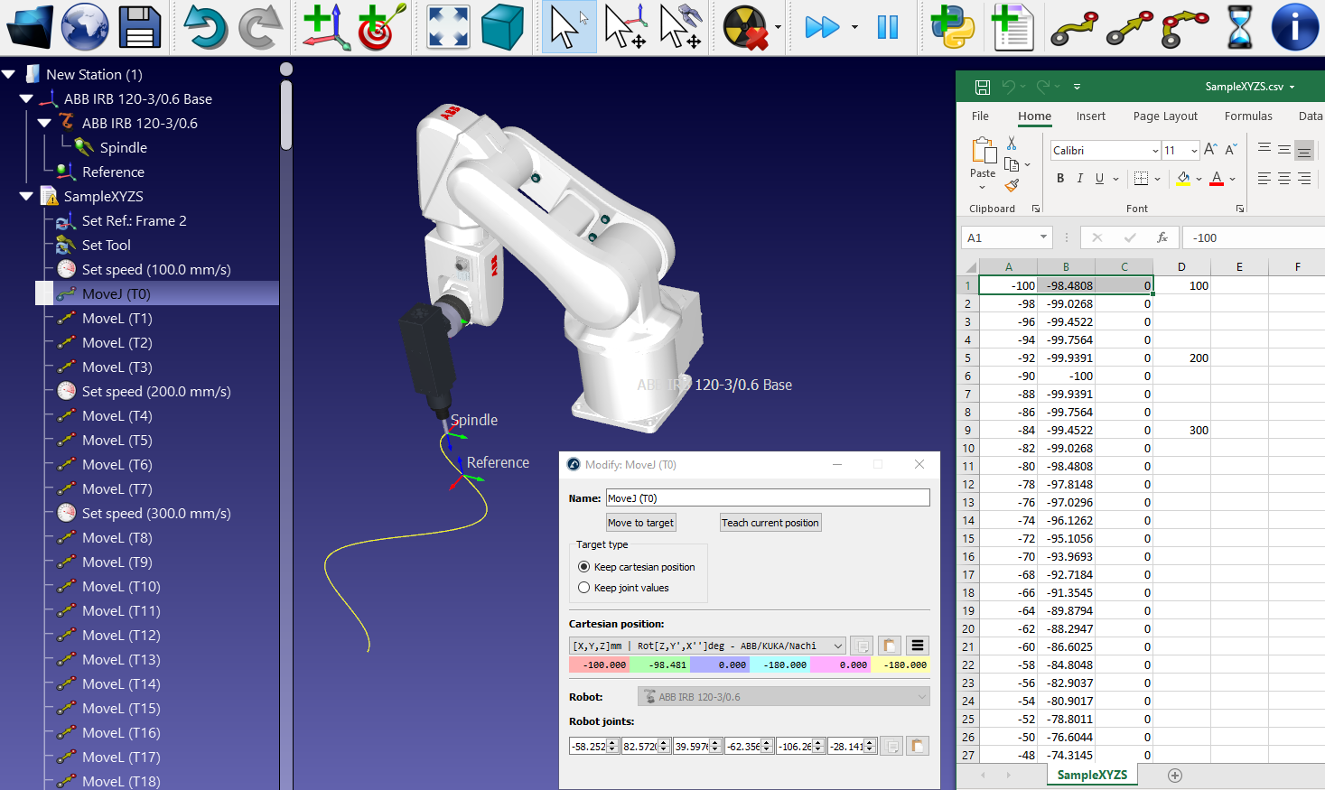
6.6. CSV file to Program (XYZ)
This example shows how to import targets from a CSV file given a list of XYZ coordinates. Optionally, the 4th column will update the speed in the program.
This example is available as a RoboDK script by default:
Select Tools-Run Script
Select ImportCSV_XYZ
Select a CSV file (Example: C:/RoboDK/Library/Scripts/SampleXYZS.csv)
- Notes:
The tool orientation of the robot is used as a reference when creating the targets.
XYZ values must be provided in millimeters, the speed must be provided in mm/s.
The active tool and reference frame will be used in the program.
The program will have instructions hidden, you can right click a program and select “Show instructions” to display the instructions.
You can select one or more movement instructions and select “Select targets” to see the targets.
# This macro shows how to load a list of XYZ points including speed
# The list must be provided as X,Y,Z,Speed. Units must be mm and mm/s respectively
from robodk.robolink import *
from robodk.robodialogs import *
from robodk.robofileio import *

#----------------------------
# Global variables:

# LOAD_AS_PROGRAM flag:
# Set to True to generate a program in the UI: we can modify targets manually and properly see the program
# Set to False, it will simulate or generate the robot program directly when running the macro
LOAD_AS_PROGRAM = True

# Set the name of the reference frame to place the targets:
REFERENCE_NAME = 'Reference CSV'

# Set the name of the reference target
# (orientation will be kept constant with respect to this target)
TARGET_NAME = 'Home'

#---------------------------
# Start the RoboDK API
RDK = Robolink()

# Ask the user to pick a file:
rdk_file_path = RDK.getParam("PATH_OPENSTATION")
path_file = getOpenFileName(rdk_file_path + "/")
if not path_file:
    print("Nothing selected")
    quit()

# Get the program name from the file path
program_name = getFileName(path_file)

# Load the CSV file as a list of list [[x,y,z,speed],[x,y,z,speed],...]
data = LoadList(path_file)

# Delete previously generated programs that follow a specific naming
#list_names = RDK.ItemList(False)
#for item_name in list_names:
#    if item_name.startswith('Auto'):
#        RDK.Item(item_name).Delete()

# Select the robot (the popup is diplayed only if there are 2 or more robots)
robot = RDK.ItemUserPick('Select a robot', ITEM_TYPE_ROBOT)
if not robot.Valid():
    raise Exception("Robot not selected or not valid")
    quit()

# Get the reference frame to generate the path
frame = RDK.Item(REFERENCE_NAME, ITEM_TYPE_FRAME)
if not frame.Valid():
    raise Exception("Reference frame not found. Use name: %s" % REFERENCE_NAME)

# Use the home target as a reference
target = RDK.Item(TARGET_NAME, ITEM_TYPE_TARGET)
if not target.Valid():
    raise Exception("Home target is not valid. Set a home target named: %s" % TARGET_NAME)

# Set the robot to the home position
robot.setJoints(target.Joints())

# Get the pose reference from the home target
pose_ref = robot.Pose()

if LOAD_AS_PROGRAM:
    # Add a new program
    program = RDK.AddProgram(program_name, robot)

    # Turn off rendering (faster)
    RDK.Render(False)

    # Speed up by not showing the instruction:
    program.ShowInstructions(False)

    # Remember the speed so that we don't set it with every instruction
    current_speed = None
    target = None

    # Very important: Make sure we set the reference frame and tool frame so that the robot is aware of it
    program.setPoseFrame(frame)
    program.setPoseTool(robot.PoseTool())

    # Iterate through all the points
    for i in range(len(data)):
        pi = pose_ref
        pi.setPos(data[i])

        # Update speed if there is a 4th column
        if len(data[i]) >= 3:
            speed = data[i][3]
            # Update the program if the speed is different than the previously set speed
            if type(speed) != str and speed != current_speed:
                program.setSpeed(speed)
                current_speed = speed

        target = RDK.AddTarget('T%i' % i, frame)
        target.setPose(pi)
        pi = target

        # Add a linear movement (with the exception of the first point which will be a joint movement)
        if i == 0:
            program.MoveJ(pi)
        else:
            program.MoveL(pi)

        # Update from time to time to notify the user about progress
        if i % 100 == 0:
            program.ShowTargets(False)
            RDK.ShowMessage("Loading %s: %.1f %%" % (program_name, 100 * i / len(data)), False)
            RDK.Render()

    program.ShowTargets(False)

else:
    # Very important: Make sure we set the reference frame and tool frame so that the robot is aware of it
    robot.setPoseFrame(frame)
    robot.setPoseTool(robot.PoseTool())

    # Remember the speed so that we don't set it with every instruction
    current_speed = None

    # Iterate through all the points
    for i in range(len(data)):
        pi = pose_ref
        pi.setPos(data[i][0:3])

        # Update speed if there is a 4th column
        if len(data[i]) >= 3:
            speed = data[i][3]
            # Update the program if the speed is different than the previously set speed
            if type(speed) != str and speed != current_speed:
                robot.setSpeed(speed)
                current_speed = speed

        # Add a linear movement (with the exception of the first point which will be a joint movement)
        if i == 0:
            robot.MoveJ(pi)
        else:
            robot.MoveL(pi)

        # Update from time to time to notify the user about progress
        #if i % 200 == 0:
        RDK.ShowMessage("Program %s: %.1f %%" % (program_name, 100 * i / len(data)), False)

RDK.ShowMessage("Done", False)
print("Done")
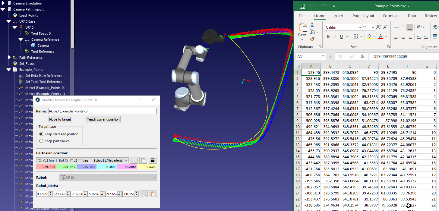
6.7. CSV file to Program (XYZWPR)
This example shows how to import targets from a CSV file given a list of XYZWPR coordinates (poses).
- This example is available as a RoboDK script by default:
Select Tools-Run Script
Select ImportCSV_XYZWPR
Select a CSV file (Example: C:/RoboDK/Library/Scripts/ImportCSV_XYZWPR.csv)
- Notes:
The Euler format Z->Y’->X’’ for target orientation is used in this example (it can be easily changed using rotx, roty and rotz functions)
XYZ values must be provided in millimeters, Rx, Ry, Rz values must be provided in degrees.
The active tool and reference frame will be used in the program.
The program will have instructions hidden, you can right click a program and select Show instructions to display the instructions.
You can select one or more movement instructions and select “Select targets” to see the targets.
# This macro can load CSV files from Denso programs in RoboDK.
# Supported types of files are:
#  1-Tool data : Tool.csv
#  2-Work object data: Work.csv
#  3-Target data: P_Var.csv
# This macro can also filter a given targets file

# Type help("robodk.robolink") or help("robodk.robomath") for more information
# Press F5 to run the script
# Visit: http://www.robodk.com/doc/PythonAPI/
# For RoboDK API documentation

from robodk.robolink import *  # API to communicate with RoboDK
from robodk.robomath import *  # Robot toolbox
from robodk.robodialogs import *
from robodk.robofileio import *

# Start communication with RoboDK
RDK = Robolink()

# Ask the user to select the robot (ignores the popup if only
ROBOT = RDK.ItemUserPick('Select a robot', ITEM_TYPE_ROBOT)

# Check if the user selected a robot
if not ROBOT.Valid():
    quit()

# Automatically retrieve active reference and tool
FRAME = ROBOT.getLink(ITEM_TYPE_FRAME)
TOOL = ROBOT.getLink(ITEM_TYPE_TOOL)

#FRAME = RDK.ItemUserPick('Select a reference frame', ITEM_TYPE_FRAME)
#TOOL = RDK.ItemUserPick('Select a tool', ITEM_TYPE_TOOL)

if not FRAME.Valid() or not TOOL.Valid():
    raise Exception("Select appropriate FRAME and TOOL references")


# Function to convert XYZWPR to a pose
# Important! Specify the order of rotation
def xyzwpr_to_pose(xyzwpr):
    x, y, z, rx, ry, rz = xyzwpr
    return transl(x, y, z) * rotz(rz * pi / 180) * roty(ry * pi / 180) * rotx(rx * pi / 180)
    #return transl(x,y,z)*rotx(rx*pi/180)*roty(ry*pi/180)*rotz(rz*pi/180)
    #return KUKA_2_Pose(xyzwpr)


# csv_file = 'C:/Users/Albert/Desktop/Var_P.csv'
csv_file = getOpenFileName(RDK.getParam('PATH_OPENSTATION'))

# Specify file codec
codec = 'utf-8'  #'ISO-8859-1'


# Load P_Var.CSV data as a list of poses, including links to reference and tool frames
def load_targets(strfile):
    csvdata = LoadList(strfile, ',', codec)
    poses = []
    idxs = []
    for i in range(0, len(csvdata)):
        x, y, z, rx, ry, rz = csvdata[i][0:6]
        poses.append(xyzwpr_to_pose([x, y, z, rx, ry, rz]))
        #idxs.append(csvdata[i][6])
        idxs.append(i)

    return poses, idxs


# Load and display Targets from P_Var.CSV in RoboDK
def load_targets_GUI(strfile):
    poses, idxs = load_targets(strfile)
    program_name = getFileName(strfile)
    program_name = program_name.replace('-', '_').replace(' ', '_')
    program = RDK.Item(program_name, ITEM_TYPE_PROGRAM)
    if program.Valid():
        program.Delete()
    program = RDK.AddProgram(program_name, ROBOT)
    program.setFrame(FRAME)
    program.setTool(TOOL)
    ROBOT.MoveJ(ROBOT.JointsHome())

    for pose, idx in zip(poses, idxs):
        name = '%s-%i' % (program_name, idx)
        target = RDK.Item(name, ITEM_TYPE_TARGET)
        if target.Valid():
            target.Delete()
        target = RDK.AddTarget(name, FRAME, ROBOT)
        target.setPose(pose)

        try:
            program.MoveJ(target)
        except Exception:
            print('Warning: %s can not be reached. It will not be added to the program' % name)


def load_targets_move(strfile):
    poses, idxs = load_targets(strfile)

    ROBOT.setFrame(FRAME)
    ROBOT.setTool(TOOL)

    ROBOT.MoveJ(ROBOT.JointsHome())

    for pose, idx in zip(poses, idxs):
        try:
            ROBOT.MoveJ(pose)
        except Exception:
            RDK.ShowMessage('Target %i can not be reached' % idx, False)


# Force just moving the robot after double clicking
#load_targets_move(csv_file)
#quit()

# Recommended mode of operation:
# 1-Double click the python file creates a program in RoboDK station
# 2-Generate program generates the program directly

MAKE_GUI_PROGRAM = False

ROBOT.setFrame(FRAME)
ROBOT.setTool(TOOL)

if RDK.RunMode() == RUNMODE_SIMULATE:
    MAKE_GUI_PROGRAM = True
    # MAKE_GUI_PROGRAM = mbox('Do you want to create a new program? If not, the robot will just move along the tagets', 'Yes', 'No')
else:
    # if we run in program generation mode just move the robot
    MAKE_GUI_PROGRAM = False

if MAKE_GUI_PROGRAM:
    RDK.Render(False)  # Faster if we turn render off
    load_targets_GUI(csv_file)
else:
    load_targets_move(csv_file)
6.8. Load a KUKA SRC file
This example shows how to import a KUKA SRC file as a robot program. Make sure to first load your KUKA robot in RoboDK (the one used for the SRC program), then, run this script using Tools -> Run-Script.
# This macro shows how to load a KUKA SRC file
# PTP movements with joint coordinates and LIN movements with Cartesian information (XYZABC) will be imported as a program.
# This macro also supports defining the tool and the base inline and changing the speed using the VEL.CP global variable

## Example program:
# DEF Milling ( )
#
# $BASE = {FRAME: X 0.000,Y -1000.000,Z 0.000,A 0.000,B 0.000,C 0.000}
# $TOOL = {FRAME: X 466.604,Y -4.165,Z 109.636,A -0.000,B 90.000,C 0.000}
#
# $VEL.CP = 1.00000
#
# PTP {A1 107.78457,A2 -44.95260,A3 141.64681,A4 107.66839,A5 -87.93467,A6 6.37710}
# LIN {X -0.000,Y -0.000,Z 6.350,A -180.000,B 0.000,C -180.000}
#
# $VEL.CP = 0.02117
# LIN {X 276.225,Y 0.000,Z 6.350,A 180.000,B 0.000,C -180.000}
# LIN {X 276.225,Y 323.850,Z 6.350,A -160.000,B 0.000,C 180.000}
# LIN {X -0.000,Y 323.850,Z 6.350,A -180.000,B -0.000,C -180.000}
# LIN {X -0.000,Y -0.000,Z 6.350,A -180.000,B 0.000,C -180.000}
# $VEL.CP = 1.00000
# LIN {X -0.000,Y -0.000,Z 106.350,A -180.000,B 0.000,C -180.000}
#
# END

from robodk.robomath import *  # Robot toolbox
from robodk.robodialogs import *
from robodk.robofileio import *
from robodk.robolink import *

#---------------------------
# Start the RoboDK API
RDK = Robolink()

# Ask the user to pick an SRC file:
rdk_file_path = RDK.getParam("PATH_OPENSTATION")
src_file_path = getOpenFileName(rdk_file_path + "/")
if not src_file_path:
    print("Nothing selected")
    quit()

# Get the program name from the file path
program_name = getFileName(src_file_path)
print("Loading program: " + program_name)

if not src_file_path.lower().endswith(".src"):
    raise Exception("Invalid file selected. Select an SRC file.")


def GetValues(line):
    """Get all the numeric values from a line"""
    # LIN {X 1671.189,Y -562.497,Z -243.070,A 173.363,B -8.525,C -113.306} C_DIS
    line = line.replace(",", " ")
    line = line.replace("}", " ")
    values = line.split(" ")

    list_values = []
    for value in values:
        try:
            value = float(value)
        except ValueError:
            continue

        list_values.append(value)

    return list_values


# Ask the user to select a robot (if more than a robot is available)
robot = RDK.ItemUserPick('Select a robot', ITEM_TYPE_ROBOT)
if not robot.Valid():
    raise Exception("Robot not selected or not valid")

# Get the active reference frame
frame = robot.getLink(ITEM_TYPE_FRAME)
if not frame.Valid():
    # If there is no active reference frame, use the robot base
    frame = robot.Parent()

# Get the active tool frame
tool = robot.getLink(ITEM_TYPE_TOOL)

# Add a new program
program = RDK.AddProgram(program_name, robot)

# Turn off rendering (faster)
RDK.Render(False)

# Speed up by not showing the instruction:
program.ShowInstructions(False)

# Open the file and iterate through each line
with open(src_file_path) as f:
    count = 0
    for line in f:
        # Remove empty characters:
        line = line.strip()
        print("Loading line: " + line)

        # Get all the numeric values in order
        values = GetValues(line)

        # Increase the counter
        count = count + 1

        # Update TCP speed (KUKA works in m/s, RoboDK works in mm/s)
        if line.startswith("$VEL.CP"):
            program.setSpeed(values[0]*1000)
            continue

        # Check operations that involve a pose
        if len(values) < 6:
            print("Warning! Invalid line: " + line)
            continue

        # Check what instruction we need to add:
        if line.startswith("LIN"):
            target = RDK.AddTarget('T%i'% count, frame)

            # Check if we have external axes information, if so, provided it to joints E1 to En
            if len(values) > 6:
                target.setJoints([0,0,0,0,0,0] + values[6:])

            target.setPose(KUKA_2_Pose(values[:6]))
            program.MoveL(target)

        # Check PTP move
        elif line.startswith("PTP"):
            target = RDK.AddTarget('T%i'% count, frame)
            target.setAsJointTarget()
            target.setJoints(values)
            program.MoveJ(target)

        # Set the tool
        elif line.startswith("$TOOL"):
            pose = KUKA_2_Pose(values[:6])
            tool = robot.AddTool(pose, "SRC TOOL")
            program.setTool(tool)

        # Set the reference frame
        elif line.startswith("$BASE"):
            frame = RDK.AddFrame("SRC BASE", robot.Parent())
            frame.setPose(KUKA_2_Pose(values[:6]))
            program.setFrame(frame)

# Hide the targets
program.ShowTargets(False)

# Show the instructions
program.ShowInstructions(True)

RDK.ShowMessage("Done", False)
print("Done")
6.9. Test Move Feasibility
This example creates a program that safely moves the robot through a set of points checking that linear movements can be achieved (including collision checking or not). The points are automatically created as a cube grid around a reference target. If a linear movement can’t be achieved from one point to the next the robot will try a joint movement if a joint movement is also not possible the point will be skipped.
# This macro shows how you can create a program that moves the robot through a set of points
# The points are automatically created as a cube grid around a reference target
# If a linear movement can't be done from one point to the next one the robot will follow a joint movement
from robodk.robolink import *  # API to communicate with RoboDK
from robodk.robomath import *  # basic matrix operations
from random import uniform  # to randomly calculate rz (rotation around the Z axis)

# Name of the reference target
REFERENCE_TARGET = 'RefTarget'

# Check for collisions
CHECK_COLLISIONS = False

#Start the RoboDK API
RDK = Robolink()

# Set collision checking ON or OFF
RDK.setCollisionActive(COLLISION_ON if CHECK_COLLISIONS else COLLISION_OFF)

# Run on robot: Force the program to run on the connected robot (same behavior as right clicking the program, then, selecting "Run on Robot")
# RDK.setRunMode(RUNMODE_RUN_ROBOT)

# Get the main/only robot in the station
robot = RDK.Item('', ITEM_TYPE_ROBOT)
if not robot.Valid():
    raise Exception("Robot not valid or not available")

# Get the active reference frame
frame = robot.getLink(ITEM_TYPE_FRAME)
if not frame.Valid():
    frame = robot.Parent()
    robot.setPoseFrame(frame)

# Get the reference pose with respect to the robot
frame_pose = robot.PoseFrame()

# Get the active tool
tool = robot.getLink(ITEM_TYPE_TOOL)
if not tool.Valid():
    tool = robot.AddTool(transl(0, 0, 75), "Tool Grid")
    robot.setPoseTool(tool)

# Get the target reference RefTarget
target_ref = RDK.Item(REFERENCE_TARGET, ITEM_TYPE_TARGET)
if not target_ref.Valid():
    target_ref = RDK.AddTarget(REFERENCE_TARGET, frame, robot)

# Get the reference position (pose=4x4 matrix of the target with respect to the reference frame)
pose_ref = target_ref.Pose()
startpoint = target_ref.Joints()
config_ref = robot.JointsConfig(startpoint)

# Retrieve the tool pose
tool_pose = tool.PoseTool()

# Retrieve the degrees of freedom or axes (num_dofs = 6 for a 6 axis robot)
num_dofs = len(robot.JointsHome().list())

# Get the reference frame of the target reference
ref_frame = target_ref.Parent()


# Function definition to check if 2 robot configurations are the same
# Configurations are set as [Rear/Front,LowerArm/UpperArm,Flip/NonFlip] bits (int values)
def config_equal(config1, config2):
    if config1[0] != config2[0] or config1[1] != config2[1] or config1[2] != config2[2]:
        return False
    return True


# Create a new program
prog = RDK.AddProgram('AutoCreated')

# This should make program generation slightly faster
#prog.ShowInstructions(False)

# Start creating the program or moving the robot:
program_or_robot = prog
program_or_robot.setPoseTool(tool_pose)

program_or_robot.MoveJ(target_ref)
lastjoints = startpoint
rz = 0
ntargets = 0
for tz in range(-100, 101, 100):
    for ty in range(0, 401, 200):
        for tx in range(100, -5001, -250):
            ntargets = ntargets + 1
            # calculate a random rotation around the Z axis of the tool
            #rz = uniform(-20*pi/180, 20*pi/180)

            # Calculate the position of the new target: translate with respect to the robot base and rotate around the tool
            newtarget_pose = transl(tx, ty, tz) * pose_ref * rotz(rz)

            # First, make sure the target is reachable:
            newtarget_joints = robot.SolveIK(newtarget_pose, lastjoints, tool_pose, frame_pose)
            if len(newtarget_joints.list()) < num_dofs:
                print('...target not reachable!! Skipping target')
                continue

            # Create a new target:
            newtarget_name = 'Auto T%.0f,%.0f,%.0f Rz=%.1f' % (tx, ty, tz, rz)
            print('Creating target %i: %s' % (ntargets, newtarget_name))
            newtarget = RDK.AddTarget(newtarget_name, ref_frame, robot)

            # At this point, the target is reachable.
            # We have to check if we can do a linear move or not. We have 2 methods:
            can_move_linear = True

            # ------------------------------
            # Validation method 1: check the joints at the destination target
            # and make sure we have the same configuration
            # A quick way to validate (it may not be perfect if robot joints can move more than 1 turn)
            # To improve this method we would have to check configurations on all possible solutions
            # from the inverse kinematics, using SolveIK_All()
            if False:
                target_joints_config = robot.JointsConfig(newtarget_joints)
                if not config_equal(config_ref, target_joints_config):
                    # We can't do a linear movement
                    can_move_linear = False
                    print("Warning! configuration is not the same as the reference target! Linear move will not be possible")

                    # update the reference configuration to the new one
                    config_ref = target_joints_config
            # -------------------------------

            # -------------------------------
            # Validation method 2: use the robot.MoveL_Test option to check if the robot can make a linear movement
            # This method is more robust and should provide a 100% accurate result but it may take more time
            # robot.MoveL_Test can also take collisions into account if collision checking is activated
            issues = robot.MoveL_Test(lastjoints, newtarget_pose)
            can_move_linear = (issues == 0)
            # We can retrieve the final joint position by retrieving the robot joints
            if can_move_linear:
                newtarget_joints = robot.Joints()

            # ---------------------------------

            if can_move_linear:
                # All good, we don't need to modify the target.
                # However, we could set the joints in the target as this may allow us to retrieve the robot configuration if we ever need it
                newtarget.setAsCartesianTarget()  # default behavior
                newtarget.setJoints(newtarget_joints)
                # It is important to have setPose after setJoints as it may recalculate the joints to match the target
                newtarget.setPose(newtarget_pose)

                # Add the linear movement
                program_or_robot.MoveL(newtarget)

            else:
                #print(newtarget_joints)
                # Check if we can do a joint movement (check for collisions)
                issues = robot.MoveJ_Test(lastjoints, newtarget_joints)
                can_move_joints = (issues == 0)
                if not can_move_joints:
                    # Skip this point
                    print("Skipping movement to: " + str(newtarget_joints))
                    continue

                # Make sure we have a joint target and a joint movement
                newtarget.setAsJointTarget()  # default behavior

                # Setting the pose for a joint target is not important unless we want to retrieve the pose later
                # or we want to use the Cartesian coordinates for post processing
                newtarget.setPose(newtarget_pose)

                # Make sure we set the joints after the pose for a joint taget as it may recalculate the pose
                newtarget.setJoints(newtarget_joints)

                # Add the joint movement
                program_or_robot.MoveJ(newtarget)

            # Remember the joint poisition of the last movement
            lastjoints = newtarget_joints

# Showing the instructions at the end is faster:
prog.ShowInstructions(True)

# Hiding the targets is cleaner and more difficult to accidentaly move a target
#prog.ShowTargets(False)

print('Program done with %i targets' % ntargets)
6.10. Docked UI
This example shows how to embed a window in RoboDK. In this case a GUI window created with TKInter is added as a docked window in RoboDK.
from tkinter import *
from robodk.robolink import *
import tkinter
import threading

# Create a new window
window = Tk()


# Close the window
def onClose():
    window.destroy()
    quit(0)


# Trigger Select button
# IMPORTANT: We need to run the action on a separate thread because
# (otherwise, if we want to interact with RoboDK window it will freeze)
def on_btnSelect():

    def thread_btnSelect():
        # Run button action (example to select an item and display its name)
        RDK = Robolink()
        item = RDK.ItemUserPick('Select an item')
        if item.Valid():
            RDK.ShowMessage("You selected the item: " + item.Name())

    threading.Thread(target=thread_btnSelect).start()


# Set the window title (must be unique for the docking to work, try to be creative)
window_title = 'RoboDK API Docked Window'
window.title(window_title)

# Delete the window when we close it
window.protocol("WM_DELETE_WINDOW", onClose)

# Add a button (Select action)
btnSelect = Button(window, text='Trigger on_btnSelect', height=5, width=60, command=on_btnSelect)
btnSelect.pack(fill=X)

# Embed the window
EmbedWindow(window_title)

# Run the window event loop. This is like an app and will block until we close the window
window.mainloop()
6.11. Estimated cycle time
This example shows how to calculate estimated cycle times.
- More information about how RoboDK estimates cycle times here:
# This example shows how to quickly calculate the cycle time of a program
# as a function of the linear and joint speeds
#
# Important notes and tips for accurate cycle time calculation:
# https://robodk.com/doc/en/General.html#CycleTime

# Start the RoboDK API
from robodk.robolink import *  # RoboDK API

RDK = Robolink()

# Ask the user to select a program
program = RDK.ItemUserPick('Select a program (make sure the program does not change the robot speed)', ITEM_TYPE_PROGRAM)

# Retrieve the robot linked to the selected program
robot = program.getLink(ITEM_TYPE_ROBOT)

# Output the linear speed, joint speed and time (separated by tabs)
writeline = "Linear Speed (mm/s)\tJoint Speed (deg/s)\tCycle Time(s)"
print(writeline)
# Prepare an HTML message we can show to the user through the RoboDK API:
msg_html = "<table border=1><tr><td>" + writeline.replace('\t', '</td><td>') + "</td></tr>"

for speed_lin in [1, 5, 10, 20, 50, 100, 200, 500]:
    for speed_joints in [1, 5, 10, 20, 50, 100, 200, 500]:
        # Set the robot speed
        robot.setSpeed(speed_lin, speed_joints)

        # Update the program and retrieve updated information:
        # https://robodk.com/doc/en/PythonAPI/robodk.html#robodk.robolink.Item.Update
        result = program.Update()
        instructions, time, travel, ok, error = result

        # Print the information
        newline = "%.1f\t%.1f\t%.1f" % (speed_lin, speed_joints, time)
        print(newline)
        msg_html = msg_html + '<tr><td>' + newline.replace('\t', '</td><td>') + '</td></tr>'

msg_html = msg_html + '</table>'

RDK.ShowMessage(msg_html)
6.12. Change tool
This macro allows updating the tool given an ID that is passed as an argument for robot machining purposes. If no ID is passed as argument it will pop up a message. This macro can be used together with a robot machining project to change the tool as it simulates. Double click your robot machining project, select Program Events, and enter SetTool(%1) for a tool change event.
# This macro allows updating the tool given an ID that is passed as an argument
# If no ID is passed as argument it will pop up a message
# This macro can be used together with a robot machining project to change the tool as it simulates
# Double click your robot machining project, select Program Events, and enter SetTool(%1) on change tool event
# https://robodk.com/doc/en/RoboDK-API.html
import sys  # allows getting the passed argument parameters
from robodk.robolink import *
from robodk.robodialogs import *

RDK = Robolink()

TOOL_ID = 0
if len(sys.argv) >= 2:
    TOOL_ID = int(sys.argv[1])
else:
    tool_str = mbox("Enter the tool number:\n(for example, for Tool 1 set 1)", entry='1')
    if not tool_str:
        # No input
        quit()
    TOOL_ID = int(tool_str)

# Select a robot
robot = RDK.Item('', ITEM_TYPE_ROBOT)
if not robot.Valid():
    raise Exception("Robot not available")

# Create the tool name
tool_name = 'Tool ' + str(TOOL_ID)
print("Using robot: " + robot.Name())
print("Setting tool: " + tool_name)

# Select the tool
tool = RDK.Item(tool_name, ITEM_TYPE_TOOL)
if not tool.Valid():
    raise Exception("Tool %s does not exist!" % tool_name)

# Update the robot to use the tool
robot.setTool(tool)

print("Done!")
6.13. Project curve to surface
This example projects the features (points/curves) to a surface and calculates the normals to the surface. This example takes 2 objects: (1) an object with curves and/or points and (2) an object with one or more surfaces.
# This example takes 2 objects:
# 1 - Object with features (curves and/or points)
# 2 - Object with surface (additional features are ignored)
# This example projects the features (points/curves) to the reference surface and calculates the normals to the surface

from robodk.robolink import *  # RoboDK API

RDK = Robolink()

# Set to True to invert the normals (flip the normals)
FlipNormals = False

# Set the type of projection
ProjectionType = PROJECTION_ALONG_NORMAL_RECALC
# Available values include:
#PROJECTION_NONE                = 0 # No curve projection
#PROJECTION_CLOSEST             = 1 # The projection will be the closest point on the surface
#PROJECTION_ALONG_NORMAL        = 2 # The projection will be done along the normal.
#PROJECTION_ALONG_NORMAL_RECALC = 3 # The projection will be done along the normal. Furthermore, the normal will be recalculated according to the surface normal.
#PROJECTION_CLOSEST_RECALC      = 4 # The projection will be the closest point on the surface and the normals will be recalculated
#PROJECTION_RECALC              = 5 # The normals are recalculated according to the surface normal of the closest projection

#-------------------------------------------------------------
# Ask the user to provide the object with the features
object_features = RDK.ItemUserPick("Select object with the features to project (curves and/or points)", ITEM_TYPE_OBJECT)
if not object_features.Valid():
    quit()

# Ask the user to provide the object with the surface used as a reference
object_surface = RDK.ItemUserPick("Select Surface Object to project features", ITEM_TYPE_OBJECT)
if not object_surface.Valid():
    quit()

# Create a duplicate copy of the surface object
object_surface.Copy()
new_object = RDK.Paste(object_surface.Parent())
new_object.setName("Recalculated Normals")
new_object.setVisible(True)

# Hide the objects used to build the new object with the desired curves
object_features.setVisible(False)
object_surface.setVisible(False)

# Turn Off rendering (faster)
RDK.Render(False)

# Add all curves, projected as desired (iterate through all curves until no more curves are found)
curve_id = 0
while True:
    # Retrieve the curve points
    curve_points, name_feature = object_features.GetPoints(FEATURE_CURVE, curve_id)
    print(name_feature)
    curve_id = curve_id + 1
    npoints = len(curve_points)
    if npoints == 0:
        break

    print("Adding curve %s with %i points" % (name_feature, npoints))
    curve_points_proj = RDK.ProjectPoints(curve_points, object_surface, ProjectionType)

    # Optionally flip the normals (ijk vector)
    if FlipNormals:
        for ci in range(len(curve_points_proj)):
            x, y, z, i, j, k = curve_points_proj[ci]
            curve_points_proj[ci] = [x, y, z, -i, -j, -k]

    RDK.AddCurve(curve_points_proj, new_object, True, PROJECTION_NONE)

# Add all points projected
point_list, name_feature = object_features.GetPoints(FEATURE_POINT)
npoints = len(point_list)
print("Adding %i points" % npoints)
if npoints > 0:
    #RDK.AddPoints(point_list, new_object, True, PROJECTION_ALONG_NORMAL_RECALC)
    point_list_proj = RDK.ProjectPoints(point_list, object_surface, ProjectionType)
    RDK.AddPoints(point_list_proj, new_object, True, PROJECTION_NONE)
    #RDK.AddCurve(curve_points, new_object, True, PROJECTION_NONE)

# Set the curve width
new_object.setValue('DISPLAY', 'LINEW=2')
# Set the curve color
new_object.setColorCurve([0.0, 0.5, 0.5])

# Turn On rendering (Optional)
RDK.Render(True)
print("Done")
6.14. Filter curve normals
This macro shows how to average the normals of an object containing curves. This macro can also filter points that are too close to each other. The user must select an object, then, a copy of this object is created with the averaged normals.
# This macro shows how to average the normals of an object containing curves.
# This macro can also filter points that are too close to each other.
# The use must select an object, then, a copy of this object is created with the normals averaged.

# For more information about the RoboDK API:
# Documentation: https://robodk.com/doc/en/RoboDK-API.html
# Reference:     https://robodk.com/doc/en/PythonAPI/index.html
#-------------------------------------------------------

# Enter the size of the average filter, in number of samples.
# If this value is set to -1 it will popup a message asking the user to enter a value
FilterNormalSamples = -1  # in samples

# Enter the distance, in mm, to filter close points.
# For example, if we want one point each 2 mm at most, we should enter 2.
# Set to -1 to not filter the number of points.
FilterPointDistance = -1  # in mm

# ------------------------------------------------------
# Start the RoboDK API
from robodk.robolink import *  # RoboDK API
from robodk.robomath import *  # Robot toolbox
from robodk.robodialogs import *

RDK = Robolink()

# Ask the user to select the object
obj = RDK.ItemUserPick("Select the object or the tool to filter curves")  # we can optionally filter by ITEM_TYPE_OBJECT or ITEM_TYPE_TOOL (not both)
# Exit if the user selects cancel
if not obj.Valid():
    quit()

# Ask the user to enter the filter size
if FilterNormalSamples <= 0:
    str_avg_filter = mbox("Enter the filter size (the number of points/normals used for the average filter).\nFor example, if the filter size is 10 units, the 10 closest normals are used to average each individual normal.", entry="10")
    if not str_avg_filter:
        # The user selected cancel
        quit()
    # Convert the user input to an integer
    FilterNormalSamples = int(str_avg_filter)
    if FilterNormalSamples <= 0:
        RDK.ShowMessage("Invalid Filter value. Enter a value >= 1", False)
        raise Exception(msg)

# Iterate through all object curves, extract the curve points and average the normals
curve_id = 0
obj_filtered = None
while True:
    points, name_feature = obj.GetPoints(FEATURE_CURVE, curve_id)
    # points is a double array of float with np points and xyzijk data for each point
    # point[np] = [x,y,z,i,j,k] # where xyz is the position and ijk is the tool orientation (Z axis, usually the normal to the surface)
    np = len(points)
    # when curve_id is out of bounds, an empty double array is returned
    if np == 0 or len(points[0]) < 6:
        break

    msg = "Filtering: " + name_feature
    print(msg)
    RDK.ShowMessage(msg, False)
    curve_id = curve_id + 1

    # For each point, average the normals in the range of points [-FilterNormalSamples/2 ; +FilterNormalSamples/2]
    new_normals = []
    for i in range(np):
        id_avg_from = round(max(0, i - 0.5 * FilterNormalSamples))
        id_avg_to = round(min(np - 1, i + 0.5 * FilterNormalSamples))

        # Make sure we account for the start and end sections (navg is usually FilterNormalSamples, except near the borders)
        n_avg = id_avg_to - id_avg_from
        normal_i = [0, 0, 0]
        for j in range(id_avg_from, id_avg_to):
            ni = points[j][3:6]
            normal_i = add3(normal_i, ni)

        # Normalize
        normal_i = normalize3(normal_i)
        #this would not be correct: normal_i = mult3(normal_i, 1.0/n_avg)

        # Add the new normal to the list
        new_normals.append(normal_i)

    # Combine the normals with the list of points
    for i in range(np):
        points[i][3:6] = new_normals[i][0:3]

    # Filter points, if desired
    if FilterPointDistance > 0:
        lastp = None
        points_filtered = []
        points_filtered.append(points[0])
        lastp = points[0]

        for i in range(1, np):
            if distance(lastp, points[i]) > FilterPointDistance:
                points_filtered.append(points[i])
                lastp = points[i]

        points = points_filtered

    # For the first curve: create a new object, rename it and place it in the same location of the original object
    if obj_filtered is None:
        obj_filtered = RDK.AddCurve(points, 0, False, PROJECTION_NONE)
        obj_filtered.setName(obj.Name() + " Filtered")
        obj_filtered.setParent(obj.Parent())
        obj_filtered.setGeometryPose(obj_filtered.GeometryPose())

    else:
        # After the first curve has been added, add following curves to the same object
        RDK.AddCurve(points, obj_filtered, True, PROJECTION_NONE)

# Set the curve display width
obj_filtered.setValue('DISPLAY', 'LINEW=2')
# Set the curve color as RGBA values [0-1.0]
obj_filtered.setColorCurve([0.0, 0.5, 1.0, 0.8])
6.15. Change curve normals
This example shows how to change the curve normal of an object to point in the +Z direction by changing the i, j and k vectors to (0,0,1).
#This Script changes the normals of the curve to point in +Z direction by changing the i,j,k vectors to (0,0,1)

#----------------------------------------
# Start the RoboDK API
from robodk.robolink import *  # RoboDK API

RDK = Robolink()

# Ask the user to select the object
obj = RDK.ItemUserPick("Select the object or the tool to filter curves")  # we can optionally filter by ITEM_TYPE_OBJECT or ITEM_TYPE_TOOL (not both)
# Exit if the user selects cancel
if not obj.Valid():
    quit()

curve_list = []
i = 0

# Iterate through all object curves, extract the curve points and retrieve the curves in a list
while True:
    curve_points, name_feature = obj.GetPoints(FEATURE_CURVE, i)
    if len(curve_points) == 0:
        break
    i = i + 1
    curve_list.append(curve_points)
# Retrieved list contains each points as [x,y,z,i,j,k]
# Change the i,j,k vectors to 0,0,1
for curve in curve_list:
    for idx in range(len(curve)):
        i, j, k = curve[idx][3:6]
        curve[idx][3:6] = [0, 0, 1]
    #print(new_curve)

#Add all maniplated curves as a new object
obj_new = None
for curve in curve_list:
    obj_new = RDK.AddCurve(curve, obj_new, True, PROJECTION_NONE)

# Set the new object name and parent
obj_new.setName(obj.Name() + " New")
obj_new.setParent(obj.Parent())
obj_new.setGeometryPose(obj_new.GeometryPose())

# Set the curve display width
obj_new.setValue('Display', 'LINEW=4')

# Set the curve color as RGBA values [0-1.0]
obj_new.setColorCurve([0.0, 0.5, 1.0, 0.8])

#Delete all curves on the object first retrieved
obj.setParam("DeleteCurves")
6.16. Attach object to a robot link
This example shows how to attach an object to a robot link. Once you place the object at the preferred position, you can run the script in your RoboDK station.
# This script allows you to attach an object to a robot link

from robodk.robolink import *  # API to communicate with RoboDK
from robodk.robodialogs import *

RDK = Robolink()  # Initialize the RoboDK API

# Select the robot
# Add the shape to a robot link
robot = RDK.ItemUserPick('Select a robot to add an object', ITEM_TYPE_ROBOT)
if not robot.Valid():
    raise Exception('No robot selected. Add a robot to attach this geometry to a link')

while True:
    value = mbox('Enter the joint to attach the object to:\n' + robot.Name() + '\nExample: 0 is the base, 3 is joint 3', entry='3')
    if not value:
        quit(0)

    link_id = int(value)
    robotlink = robot.ObjectLink(link_id)
    if robotlink.Valid():
        break

    RDK.ShowMessage("Invalid link. Select a valid robot link")

object = RDK.ItemUserPick('Select the object to add', ITEM_TYPE_OBJECT)
if not object.Valid():
    raise Exception('Object not selected')

# List of objects to merge (first one must be the robot link)
merge = [robotlink, object]

# Merge the object
RDK.MergeItems(merge)

# Set original object invisible (or delete)
object.setVisible(False)
# object.Delete()
6.17. Move robot using a keyboard
This example shows how to move the robot using the keyboard. This macro needs to be executed as a separate process to properly intercept the keyboard (not within RoboDK). This example could be extended to move the robot using an Xbox controller, a Wii Remote or any other input device. You can find the Game Controller Add-in in the Add-in Marketplace.
# This macro allows moving a robot using the keyboard
# More information about the RoboDK API here:
# https://robodk.com/doc/en/RoboDK-API.html
# Type help("robodk.robolink") or help("robodk.robomath") for more information
# Press F5 to run the script
# Note: you do not need to keep a copy of this file, your python script is saved with the station
from robodk.robolink import *  # API to communicate with RoboDK
from robodk.robomath import *  # basic matrix operations

RDK = Robolink()

# Arrow keys program example

# get a robot
robot = RDK.Item('', ITEM_TYPE_ROBOT)
if not robot.Valid():
    print("No robot in the station. Load a robot first, then run this program.")
    pause(5)
    raise Exception("No robot in the station!")

print('Using robot: %s' % robot.Name())
print('Use the arrows (left, right, up, down), Q and A keys to move the robot')
print('Note: This works on console mode only, you must run the PY file separately')

# define the move increment
move_speed = 10

from msvcrt import getch
while True:
    key = (ord(getch()))
    move_direction = [0, 0, 0]
    # print(key)
    if key == 75:
        print('arrow left (Y-)')
        move_direction = [0, -1, 0]
    elif key == 77:
        print('arrow right (Y+)')
        move_direction = [0, 1, 0]
    elif key == 72:
        print('arrow up (X-)')
        move_direction = [-1, 0, 0]
    elif key == 80:
        print('arrow down (X+)')
        move_direction = [1, 0, 0]
    elif key == 113:
        print('Q (Z+)')
        move_direction = [0, 0, 1]
    elif key == 97:
        print('A (Z-)')
        move_direction = [0, 0, -1]

    # make sure that a movement direction is specified
    if norm(move_direction) <= 0:
        continue

    # calculate the movement in mm according to the movement speed
    xyz_move = mult3(move_direction, move_speed)

    # get the robot joints
    robot_joints = robot.Joints()

    # get the robot position from the joints (calculate forward kinematics)
    robot_position = robot.SolveFK(robot_joints)

    # get the robot configuration (robot joint state)
    robot_config = robot.JointsConfig(robot_joints)

    # calculate the new robot position
    new_robot_position = transl(xyz_move) * robot_position

    # calculate the new robot joints
    new_robot_joints = robot.SolveIK(new_robot_position)
    if len(new_robot_joints.tolist()) < 6:
        print("No robot solution!! The new position is too far, out of reach or close to a singularity")
        continue

    # calculate the robot configuration for the new joints
    new_robot_config = robot.JointsConfig(new_robot_joints)

    if robot_config[0] != new_robot_config[0] or robot_config[1] != new_robot_config[1] or robot_config[2] != new_robot_config[2]:
        print("Warning!! Robot configuration changed!! This will lead to unextected movements!")
        print(robot_config)
        print(new_robot_config)
    else:

        # move the robot joints to the new position
        robot.MoveJ(new_robot_joints)
        #robot.MoveL(new_robot_joints)
6.18. Connect to Robots
This example shows how to connect to all robots available in the RoboDK station using robot drivers and move the robot to the positions set in RoboDK. This example shows how to communicate with more than one robot at the same time.
- More information here:
Online programming using the RoboDK API for Python: https://robodk.com/doc/en/RoboDK-API.html#PythonAPIOnline
Robot drivers: https://robodk.com/doc/en/Robot-Drivers.html#RobotDrivers
# Type help("robodk.robolink") or help("robodk.robomath") for more information
# Press F5 to run the script
# More information about the RoboDK API here:
# https://robodk.com/doc/en/RoboDK-API.html
# Note: you do not need to keep a copy of this file, your python script is saved with the station
from robodk.robolink import *  # API to communicate with RoboDK

# Start RoboDK API
RDK = Robolink()

# gather all robots as item objects
robots = RDK.ItemList(ITEM_TYPE_ROBOT, False)

# loop through all the robots and connect to the robot
errors = ''
count = 0
for robot in robots:
    count = count + 1

    # force disconnect from all robots by simulating a double click
    #if count == 0:
    #    robot.Disconnect()
    #    robot.Disconnect()
    #    pause(1)

    # Important, each robot needs a new API connection to allow moving them separately in different threads (if required)
    rdk = Robolink()
    robot.link = rdk

    # Force simulation mode in case we are already connected to the robot.
    # Then, gather the joint position of the robots.
    # This will gather the position of the simulated robot instead of the real robot.
    rdk.setRunMode(RUNMODE_SIMULATE)
    jnts = robot.Joints()

    # connect to the robot:
    # rdk.setRunMode(RUNMODE_RUN_ROBOT) # not needed because connect will automatically do it
    # state = robot.ConnectSafe()
    state = robot.Connect()
    print(state)

    # Check the connection status and message
    state, msg = robot.ConnectedState()
    print(state)
    print(msg)
    if state != ROBOTCOM_READY:
        errors = errors + 'Problems connecting: ' + robot.Name() + ': ' + msg + '\n'
    else:
        # move to the joint position in the simulator:
        robot.MoveJ(jnts, False)

# Display connection errors, if any
if len(errors) > 0:
    print(errors)
    raise Exception(errors)
else:
    quit(0)
6.19. Monitor Joints
This example shows how to save the simulated position of a robot to a text or CSV file.
# This macro will record the robot joints (in degrees) in a CSV file (including a time stamp in seconds). This file avoids recording the same joints twice.
# Tip: Use the script JointsPlayback.py to move along the recorded joints

from robodk.robolink import *  # API to communicate with RoboDK
from robodk.robomath import *  # basic matrix operations
from time import gmtime, strftime

RDK = Robolink()

# Ask the user to select a robot arm (mechanisms are ignored)
robot = RDK.ItemUserPick('Select a robot', ITEM_TYPE_ROBOT_ARM)
if not robot.Valid():
    raise Exception("Robot is not available")

# Generate a file in the same folder where we have the RDK file
file_path = RDK.getParam('PATH_OPENSTATION') + '/joints-' + strftime("%Y-%m-%d %H-%M-%S", gmtime()) + '.csv'


def joints_changed(j1, j2, tolerance=0.0001):
    """Returns True if joints 1 and joints 2 are different"""
    if j1 is None or j2 is None:
        return True

    for j1, j2 in zip(j1, j2):
        if abs(j1 - j2) > tolerance:
            return True

    return False


# Infinite loop to record robot joints
joints_last = None
print("Recording robot joints to file: " + file_path)
with open(file_path, 'a') as fid:
    tic()
    while True:
        time = toc()
        joints = robot.Joints().list()
        if joints_changed(joints, joints_last):
            print('Time (s): ' + str(time))
            fid.write(str(joints)[1:-1] + (", %.3f" % time) + '\n')
            joints_last = joints
            pause(0.01)
6.20. Monitor a Real UR robot
This example shows how to monitor a Universal Robot connected to a PC. Among other things, the position of the robot, speed and acceleration can be monitored at 125 Hz.
- More information here:
Robot drivers: https://robodk.com/doc/en/Robot-Drivers.html#RobotDrivers
Tips for using Universal Robots: https://robodk.com/doc/en/Robots-Universal-Robots.html#UR
# This script creates a thread to monitor the position and other variables from a real UR robot
# With this script active, RoboDK will create a new target when the robot is moved a certain tolerance
#
# More information about the RoboDK API here:
# https://robodk.com/doc/en/RoboDK-API.html
# Press F5 to run the script
# Or visit: https://robodk.com/doc/en/PythonAPI/index.html
from robodk.robolink import *  # API to communicate with RoboDK
from robodk.robomath import *  # Robot toolbox
import threading
import socket
import struct
import os
import time

# Refresh the screen every time the robot position changes
TOLERANCE_JOINTS_REFRESH = 0.1
RETRIEVE_JOINTS_ONCE = False  # If True, the current robot position will be retrieved once only

# Create targets given a tolerance in degrees
CREATE_TARGETS = False
TOLERANCE_JOINTS_NEWTARGET = 10  # in degrees

REFRESH_RATE = 0.01

# Make current robot joints accessible in case we run it on a separate thread
global ROBOT_JOINTS


# Procedure to check if robot joint positions are different according to a certain tolerance
def Robot_Joints_Check(jA, jB, tolerance_deg=1):
    if jA is None:
        return True

    for i in range(6):
        if abs(jA[i] - jB[i]) > tolerance_deg * pi / 180:
            return True
    return False


#########################################################################
# Byte shifts to point to the right byte data inside a packet
UR_GET_TIME = 1
UR_GET_JOINT_POSITIONS = 252
UR_GET_JOINT_SPEEDS = 300
UR_GET_JOINT_CURRENTS = 348
UR_GET_TCP_FORCES = 540


# Get packet size according to the byte array
def packet_size(buf):
    if len(buf) < 4:
        return 0
    return struct.unpack_from("!i", buf, 0)[0]


# Check if a packet is complete
def packet_check(buf):
    msg_sz = packet_size(buf)
    if len(buf) < msg_sz:
        print("Incorrect packet size %i vs %i" % (msg_sz, len(buf)))
        return False

    return True


# Get specific information from a packet
def packet_value(buf, offset, nval=6):
    if len(buf) < offset + nval:
        print("Not available offset (maybe older Polyscope version?): %i - %i" % (len(buf), offset))
        return None
    format = '!'
    for i in range(nval):
        format += 'd'
    return list(struct.unpack_from(format, buf, offset))  #return list(struct.unpack_from("!dddddd", buf, offset))


# Action to take when a new packet arrives
def on_packet(packet):
    global ROBOT_JOINTS
    # Retrieve desired information from a packet
    rob_joints_RAD = packet_value(packet, UR_GET_JOINT_POSITIONS)
    ROBOT_JOINTS = [ji * 180.0 / pi for ji in rob_joints_RAD]
    #ROBOT_SPEED = packet_value(packet, UR_GET_JOINT_SPEEDS)
    #ROBOT_CURRENT = packet_value(packet, UR_GET_JOINT_CURRENTS)
    #print(ROBOT_JOINTS)


# Monitor thread to retrieve information from the robot
def UR_Monitor():
    while True:
        rt_socket = socket.create_connection((ROBOT_IP, ROBOT_PORT))
        buf = b''
        packet_count = 0
        packet_time_last = time.time()
        while True:
            more = rt_socket.recv(4096)
            if more:
                buf = buf + more
                if packet_check(buf):
                    packet_len = packet_size(buf)
                    packet, buf = buf[:packet_len], buf[packet_len:]
                    on_packet(packet)
                    packet_count += 1
                    if packet_count % 125 == 0:
                        t_now = time.time()
                        print("Monitoring at %.1f packets per second" % (packet_count / (t_now - packet_time_last)))
                        packet_count = 0
                        packet_time_last = t_now

        rt_socket.close()


#########################################################################

# Enter RoboDK IP and Port
ROBOT_IP = None  #'192.168.2.31'
ROBOT_PORT = 30003

# Start RoboDK API
RDK = Robolink()

# Retrieve a robot
robot = RDK.ItemUserPick('Select a UR robot to retrieve current position', ITEM_TYPE_ROBOT)
if not robot.Valid():
    quit()

# Retrieve Robot's IP:
if ROBOT_IP is None:
    ip, port, path, ftpuser, ftppass = robot.ConnectionParams()
    ROBOT_IP = ip

ROBOT_JOINTS = None
last_joints_target = None
last_joints_refresh = None

# Start the Robot Monitor thread
#q = queue.Queue()
t = threading.Thread(target=UR_Monitor)
t.daemon = True
t.start()
#UR_Monitor()

# Start the main loop to refresh RoboDK and create targets/programs automatically
target_count = 0
while True:
    # Wait for a valid robot joints reading
    if ROBOT_JOINTS is None:
        continue

    # Set the robot to that position
    if Robot_Joints_Check(last_joints_refresh, ROBOT_JOINTS, TOLERANCE_JOINTS_REFRESH):
        last_joints_refresh = ROBOT_JOINTS
        robot.setJoints(ROBOT_JOINTS)

    # Stop here if we need only the current position
    if RETRIEVE_JOINTS_ONCE:
        quit(0)

    # Check if the robot has moved enough to create a new target
    if CREATE_TARGETS and Robot_Joints_Check(last_joints_target, ROBOT_JOINTS, TOLERANCE_JOINTS_NEWTARGET):
        last_joints_target = ROBOT_JOINTS
        target_count = target_count + 1
        newtarget = RDK.AddTarget('T %i' % target_count, 0, robot)

    # Take a short break
    pause(REFRESH_RATE)
6.21. Pick and Place
This example shows an advanced pick and place application using a Fanuc M-710iC/50 robot (Example 2 from the RoboDK library).
In this example all the robot movements of the Fanuc robot are managed by the Python program. Using the Python API it is possible to create, move, modify and delete any object, reference frame, robot or other items in the station.
# Type help("robolink") or help("robodk") for more information
# Press F5 to run the script
# Documentation: https://robodk.com/doc/en/RoboDK-API.html
# Reference:     https://robodk.com/doc/en/PythonAPI/index.html
#
# This example shows an advanced pick and place application using a Fanuc M-710iC/50 robot (Example 2 from the RoboDK library)

from robodk.robolink import *  # API to communicate with RoboDK for simulation and offline/online programming
from robodk.robomath import *  # Robot toolbox

# Setup global parameters
BALL_DIAMETER = 100  # diameter of one ball
APPROACH = 100  # approach distance to grab each part, in mm
nTCPs = 6  # number of TCP's in the tool

#----------------------------------------------
# Function definitions


def box_calc(BALLS_SIDE=4, BALLS_MAX=None):
    """Calculate a list of points (ball center) as if the balls were stored in a box"""
    if BALLS_MAX is None:
        BALLS_MAX = BALLS_SIDE**3
    xyz_list = []
    for h in range(BALLS_SIDE):
        for i in range(BALLS_SIDE):
            for j in range(BALLS_SIDE):
                xyz_list = xyz_list + [[(i + 0.5) * BALL_DIAMETER, (j + 0.5) * BALL_DIAMETER, (h + 0.5) * BALL_DIAMETER]]
                if len(xyz_list) >= BALLS_MAX:
                    return xyz_list
    return xyz_list


def pyramid_calc(BALLS_SIDE=4):
    """Calculate a list of points (ball center) as if the balls were place in a pyramid"""
    #the number of balls can be calculated as: int(BALLS_SIDE*(BALLS_SIDE+1)*(2*BALLS_SIDE+1)/6)
    BALL_DIAMETER = 100
    xyz_list = []
    sqrt2 = 2**(0.5)
    for h in range(BALLS_SIDE):
        for i in range(BALLS_SIDE - h):
            for j in range(BALLS_SIDE - h):
                height = h * BALL_DIAMETER / sqrt2 + BALL_DIAMETER / 2
                xyz_list = xyz_list + [[i * BALL_DIAMETER + (h + 1) * BALL_DIAMETER * 0.5, j * BALL_DIAMETER + (h + 1) * BALL_DIAMETER * 0.5, height]]
    return xyz_list


def balls_setup(frame, positions):
    """Place a list of balls in a reference frame. The reference object (ball) must have been previously copied to the clipboard."""
    nballs = len(positions)
    step = 1.0 / (nballs - 1)
    for i in range(nballs):
        newball = frame.Paste()
        newball.setName('ball ' + str(i))  #set item name
        newball.setPose(transl(positions[i]))  #set item position with respect to parent
        newball.setVisible(True, False)  #make item visible but hide the reference frame
        newball.Recolor([1 - step * i, step * i, 0.2, 1])  #set RGBA color


def cleanup_balls(parentnodes):
    """Delete all child items whose name starts with \"ball\", from the provided list of parent items."""
    todelete = []
    for item in parentnodes:
        todelete = todelete + item.Childs()

    for item in todelete:
        if item.Name().startswith('ball'):
            item.Delete()


def TCP_On(toolitem, tcp_id):
    """Attach the closest object to the toolitem tool pose,
    furthermore, it will output appropriate function calls on the generated robot program (call to TCP_On)"""
    toolitem.AttachClosest()
    toolitem.RDK().RunMessage('Set air valve %i on' % (tcp_id + 1))
    toolitem.RDK().RunProgram('TCP_On(%i)' % (tcp_id + 1))


def TCP_Off(toolitem, tcp_id, itemleave=0):
    """Detaches the closest object attached to the toolitem tool pose,
    furthermore, it will output appropriate function calls on the generated robot program (call to TCP_Off)"""
    toolitem.DetachAll(itemleave)
    toolitem.RDK().RunMessage('Set air valve %i off' % (tcp_id + 1))
    toolitem.RDK().RunProgram('TCP_Off(%i)' % (tcp_id + 1))


#----------------------------------------------------------
# The program starts here:

# Any interaction with RoboDK must be done through RDK:
RDK = Robolink()

# Turn off automatic rendering (faster)
RDK.Render(False)

#RDK.Set_Simulation_Speed(500); # set the simulation speed

# Gather required items from the station tree
robot = RDK.Item('Fanuc M-710iC/50')
robot_tools = robot.Childs()
#robottool = RDK.Item('MainTool')
frame1 = RDK.Item('Table 1')
frame2 = RDK.Item('Table 2')

# Copy a ball as an object (same as CTRL+C)
ballref = RDK.Item('reference ball')
ballref.Copy()

# Run a pre-defined station program (in RoboDK) to replace the two tables
prog_reset = RDK.Item('Replace objects')
prog_reset.RunProgram()

# Call custom procedure to remove old objects
cleanup_balls([frame1, frame2])

# Make a list of positions to place the objects
frame1_list = pyramid_calc(4)
frame2_list = pyramid_calc(4)

# Programmatically place the objects with a custom-made procedure
balls_setup(frame1, frame1_list)

# Delete previously generated tools
for tool in robot_tools:
    if tool.Name().startswith('TCP'):
        tool.Delete()

# Calculate tool frames for the suction cup tool of 6 suction cups
TCP_list = []
for i in range(nTCPs):
    TCPi_pose = transl(0, 0, 100) * rotz((360 / nTCPs) * i * pi / 180) * transl(125, 0, 0) * roty(pi / 2)
    TCPi = robot.AddTool(TCPi_pose, 'TCP %i' % (i + 1))
    TCP_list.append(TCPi)

TCP_0 = TCP_list[0]

# Turn on automatic rendering
RDK.Render(True)

# Move balls
robot.setPoseTool(TCP_list[0])
nballs_frame1 = len(frame1_list)
nballs_frame2 = len(frame2_list)
idTake = nballs_frame1 - 1
idLeave = 0
idTCP = 0
target_app_frame = transl(2 * BALL_DIAMETER, 2 * BALL_DIAMETER, 4 * BALL_DIAMETER) * roty(pi) * transl(0, 0, -APPROACH)

while idTake >= 0:
    # ------------------------------------------------------------------
    # first priority: grab as many balls as possible
    # the tool is empty at this point, so take as many balls as possible (up to a maximum of 6 -> nTCPs)
    ntake = min(nTCPs, idTake + 1)

    # approach to frame 1
    robot.setPoseFrame(frame1)
    robot.setPoseTool(TCP_0)
    robot.MoveJ([0, 0, 0, 0, 10, -200])
    robot.MoveJ(target_app_frame)

    # grab ntake balls from frame 1
    for i in range(ntake):
        TCPi = TCP_list[i]
        robot.setPoseTool(TCPi)
        # calculate target wrt frame1: rotation about Y is needed since Z and X axis are inverted
        target = transl(frame1_list[idTake]) * roty(pi) * rotx(30 * pi / 180)
        target_app = target * transl(0, 0, -APPROACH)
        idTake = idTake - 1
        robot.MoveL(target_app)
        robot.MoveL(target)
        TCP_On(TCPi, i)
        robot.MoveL(target_app)

    # ------------------------------------------------------------------
    # second priority: unload the tool
    # approach to frame 2 and place the tool balls into table 2
    robot.setPoseTool(TCP_0)
    robot.MoveJ(target_app_frame)
    robot.MoveJ([0, 0, 0, 0, 10, -200])
    robot.setPoseFrame(frame2)
    robot.MoveJ(target_app_frame)
    for i in range(ntake):
        TCPi = TCP_list[i]
        robot.setPoseTool(TCPi)
        if idLeave > nballs_frame2 - 1:
            raise Exception("No room left to place objects in Table 2")

        # calculate target wrt frame1: rotation of 180 about Y is needed since Z and X axis are inverted
        target = transl(frame2_list[idLeave]) * roty(pi) * rotx(30 * pi / 180)
        target_app = target * transl(0, 0, -APPROACH)
        idLeave = idLeave + 1
        robot.MoveL(target_app)
        robot.MoveL(target)
        TCP_Off(TCPi, i, frame2)
        robot.MoveL(target_app)

    robot.MoveJ(target_app_frame)

# Move home when the robot finishes
robot.MoveJ([0, 0, 0, 0, 10, -200])
6.22. Update Machining Tools
This script will update all tools that have a Length flag in the tool name (Example: Tool L220.551) with respect to a reference tool. The reference tool must have a reference Length (example: Calib Point L164.033). This is useful to specify a standoff or define a specific milling tool with respect to a reference tool.
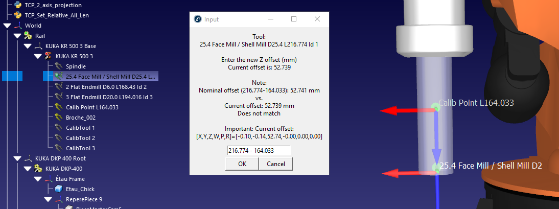
# This macro will update all tools that have a Length flag in the tool name (Tool L220.551) with respect to a reference tool.
# The reference tool must have a reference Length (example: Calib Point L164.033).
# This is useful to specify a standoff or define a specific milling tool with respect to a reference tool.
# Tip: Define the first tool with a length of 0 Example: Spindle L0 and it will be placed at the root of the tool holder
#
# More information about the RoboDK API here:
# https://robodk.com/doc/en/RoboDK-API.html
# For more information visit:
# https://robodk.com/doc/en/PythonAPI/robodk.html#robolink-py

from robodk.robolink import *  # RoboDK API
from robodk.robomath import *  # Robot toolbox
from robodk.robodialogs import *

# Name of the reference tool (name in the RoboDK tree)
# The name must contain the length in mm
TOOL_NAME_REF = 'Calib Point L164.033'


# Get the nominal tool length based on the tool name and the L keyword
def get_len_tool(toolname):
    toolnamelist = toolname.split(" ")
    for w in toolnamelist:
        if w.startswith("L"):
            try:
                len_tcp_definition = float(w[1:])
                return len_tcp_definition
            except ValueError:
                print("Unable to convert word: " + str(w))
                continue

    print("Warning! Unknown length")
    return None


# Start the API
RDK = Robolink()

# Retrieve the reference tool and make sure it exists
tcpref1 = RDK.Item(TOOL_NAME_REF, ITEM_TYPE_TOOL)
if not tcpref1.Valid():
    raise Exception('The reference TCP does not exist')

# Get the reference length
len_ref = get_len_tool(tcpref1.Name())
if len_ref is None:
    print("Reference length not specified, 0 assumed")
    len_ref = 0

# Retrieve the pose of both tools
pose1 = tcpref1.PoseTool()

# Iterate through all tools
for tcpref2 in tcpref1.Parent().Childs():

    if tcpref2.Type() != ITEM_TYPE_TOOL:
        # Not a tool item, skip
        continue

    if tcpref1 == tcpref2:
        # this is the same tool, skip
        continue

    # Get the tool pose
    pose2 = tcpref2.PoseTool()

    # Retrieve the current relationship:
    pose_shift = invH(pose1) * pose2
    x, y, z, w, p, r = Pose_2_TxyzRxyz(pose_shift)

    # Variable that holds the new offset along Z axis
    newZ = None

    toolname = tcpref2.Name()
    len_tcp_definition = get_len_tool(toolname)
    if len_tcp_definition is None:
        print("Skipping tool without L length: " + toolname)
        continue

    # Calculate the offset according to "L" naming:
    nominal_offset = len_tcp_definition - len_ref

    while True:
        message = 'Tool:\n%s\n\nEnter the new Z offset (mm)\nCurrent offset is: %.3f' % (toolname, z)

        if abs(nominal_offset - z) > 0.001:
            message += '\n\nNote:\nNominal offset (%.3f-%.3f): %.3f mm\nvs.\nCurrent offset: %.3f mm\nDoes not match' % (len_tcp_definition, len_ref, nominal_offset, z)
        else:
            message += '\nOffset currently matches'

        if abs(x) > 0.001 or abs(y) > 0.001 or abs(w) > 0.001 or abs(p) > 0.001 or abs(r) > 0.001:
            message += '\n\nImportant: Current offset:\n[X,Y,Z,W,P,R]=[%.2f,%.2f,%.2f,%.2f,%.2f,%.2f]' % (x, y, z, w, p, r)

        value = mbox(message, entry=('%.3f - %.3f' % (len_tcp_definition, len_ref)))

        if value is False:
            print("Cancelled by the user")
            #quit()# stop
            break  # go to next

        try:
            newZ = eval(value)  #float(value)
            break
        except ValueError:
            print("This is not a number, try again")

    # Update the tool if an offset has been calculated
    if newZ is not None:
        pose_newtool = pose1 * transl(0, 0, newZ)
        tcpref2.setPoseTool(pose_newtool)
        print("Done. Pose set to:")
        print(pose_newtool)
6.23. Project TCP to Axis
This script projects a tool (TCP) to an axis defined by two other calibrated tools (two TCP that define an axis). This script also aligns the tool orientation (axis Z) to match the calibrated axis. A popup will be displayed to provide the tool errors before you update the TCP.
This script is useful if the point and axis of a spindle needs to be accurately calculated (for example, for robot machining or cutting).
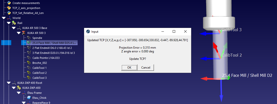
# This script projects a TCP to an axis defined by two other TCPs,
# adjusting the position of the TCP and the Z axis along the line defined by the two calibration TCPs
#
# More information about the RoboDK API here:
# https://robodk.com/doc/en/RoboDK-API.html
# For more information visit:
# https://robodk.com/doc/en/PythonAPI/robodk.html#robolink-py

# Enter the calibrated reference tools (Z+ defined as Point1 to Point2)
AXIS_POINT_1 = 'CalibTool 1'
AXIS_POINT_2 = 'CalibTool 2'

# Set the following variable to False to not move the TCP
# (only a reorientation of the Z axis will be done)
PROJECT_POINT = True

#-----------------------------------------------------------------
#-----------------------------------------------------------------
#-----------------------------------------------------------------
#-----------------------------------------------------------------
#-----------------------------------------------------------------

from robodk.robolink import *  # API to communicate with RoboDK
from robodk.robomath import *  # basic matrix operations
from robodk.robodialogs import *

RDK = Robolink()

# Get TCP to project
tcpitem = RDK.ItemUserPick('Select a tool to calibrate Z axis', ITEM_TYPE_TOOL)

if not tcpitem.Valid():
    quit()

H_TCP = tcpitem.PoseTool()
P_TCP = H_TCP.Pos()

# Get spindle axis
tcp_item_1 = RDK.Item(AXIS_POINT_1, ITEM_TYPE_TOOL)
tcp_item_2 = RDK.Item(AXIS_POINT_2, ITEM_TYPE_TOOL)

if not tcp_item_1.Valid():
    raise Exception("Define the first calibration TCP as: %s" % AXIS_POINT_1)

if not tcp_item_2.Valid():
    raise Exception("Define the second calibration TCP as: %s" % AXIS_POINT_2)

axis_p1 = tcp_item_1.PoseTool().Pos()
axis_p2 = tcp_item_2.PoseTool().Pos()

# Alternative Manual input for P_TCP:
# P_TCP = [ -51.240000,   -94.004000,   266.281000,    60.150000,     0.000000,   -26.760000  ] # [2,0,10]
# H_TCP = Motoman_2_Pose(P_TCP)

# Alternative manual input for spindle axis
# axis_p1 = [-43.74331, -83.59345, 259.19644]  #[0,0,0]
# axis_p2 = [-56.48556, -107.99492, 274.96115] #[0,0,1]
axis_v12 = normalize3(subs3(axis_p2, axis_p1))

# TCP calculation
TCP_OK = proj_pt_2_line(P_TCP, axis_p1, axis_v12)

TCP_verror = subs3(P_TCP, TCP_OK)

print('Projected TCP to Spindle axis:\n[X,Y,Z] = [%.3f,%.3f,%.3f] mm' % (TCP_OK[0], TCP_OK[1], TCP_OK[2]))
msg_proj_error = 'Projection Error = %.3f mm' % norm(TCP_verror)
print(msg_proj_error)

# TCP reference frame adjustment (correct Z axis)
TCP_Yvect = H_TCP.VY()
TCP_Zvect = H_TCP.VZ()

angle_error = angle3(axis_v12, TCP_Zvect) * 180 / pi
msg_angle_error = 'Z angle error = %.3f deg' % angle_error
print(msg_angle_error)
H_TCP_OK = eye(4)
if PROJECT_POINT:
    H_TCP_OK[0:3, 3] = TCP_OK
else:
    H_TCP_OK[0:3, 3] = P_TCP

H_TCP_OK[0:3, 2] = axis_v12
x_axis = normalize3(cross(TCP_Yvect, axis_v12))
y_axis = normalize3(cross(axis_v12, x_axis))
H_TCP_OK[0:3, 0] = x_axis
H_TCP_OK[0:3, 1] = y_axis

TCP_OK = Pose_2_Motoman(H_TCP_OK)
msg_newtcp = 'Updated TCP [X,Y,Z,w,p,r] = [%.3f,%.3f,%.3f,%.3f,%.3f,%.3f]' % (TCP_OK[0], TCP_OK[1], TCP_OK[2], TCP_OK[3], TCP_OK[4], TCP_OK[5])
print(msg_newtcp)

# Ask user to update TCP
answer = mbox(msg_newtcp + '\n\n' + msg_proj_error + '\n' + msg_angle_error + '\n\nUpdate TCP?')
if answer == True:
    tcpitem.setPoseTool(H_TCP_OK)
6.24. Robot Machining Settings
This example shows how to modify settings related to robot machining and program events using the RoboDK API.
Double click a robot machining project, curve follow project, point follow project or 3D printing project to see the settings.
Select Program Events to see the events.
Next section shows how to change the axes optimization settings (may be needed when a robot is combined with external axes).
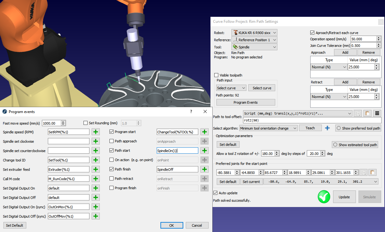
The variables can be retrieved or set as a dict or JSON string using the parameter/command Machining and ProgEvents as shown in the following example.
# This example shows how to modify settings related to robot machining and program events using the RoboDK API.
# Double click a robot machining project, curve follow project, point follow project or 3D printing project to see the settings.
# Select *Program Events* to see the events.
# More information here:
# https://robodk.com/doc/en/PythonAPI/examples.html#robot-machining-settings

from robodk.robolink import *  # RoboDK API

# JSON tools
import json

# Ask the user to select a robot machining project
RDK = Robolink()
m = RDK.ItemUserPick('Select a robot machining project to change approach/retract', ITEM_TYPE_MACHINING)
if not m.Valid():
    raise Exception("Add a robot machining project, curve follow or point follow")

# Get the robot used by this robot machining project:
robot = m.getLink(ITEM_TYPE_ROBOT)
if not robot.Valid():
    print("Robot not selected: select a robot for this robot machining project")
    quit()

#--------------------------------------------
# Get or set preferred start joints:
joints = m.Joints()
joints = robot.JointsHome()
print("Preferred start joints:")
print(joints.list())
m.setJoints(joints)

# Get or set the path to tool pose:
path2tool = m.Pose()
print("Path to tool pose:")
print(path2tool)
m.setPose(path2tool)

# Get or set the tool / reference frame:
tool = m.getLink(ITEM_TYPE_TOOL)
print("Using tool: " + tool.Name())
frame = m.getLink(ITEM_TYPE_FRAME)
print("Using reference: " + frame.Name())
#m.setPoseFrame(frame)
#m.setPoseTool(tool)

#--------------------------------------------
# Get or set robot machining parameters
# Read Program Events settings for selected machining project
machiningsettings = m.setParam("Machining")
print("Robot machining settings:")
print(json.dumps(machiningsettings, indent=4))

#--------------------------------------------
# Read Program Events settings for selected machining project
progevents = m.setParam("ProgEvents")
print("Program events:")
print(json.dumps(progevents, indent=4))

# Read Program Events settings used by default
#station = RDK.ActiveStation()
#json_data = station.setParam("ProgEvents")
#json_object = json.loads(json_data)
#print(json.dumps(json_object, indent=4))

# Sample dict for robot machining settings
MachiningSettings = {
    "Algorithm": 0,  # 0: minimum tool orientation change, 1: tool orientation follows path
    "ApproachRetractAll": 1,
    "AutoUpdate": 0,
    "AvoidCollisions": 0,
    "FollowAngle": 45,
    "FollowAngleOn": 1,
    "FollowRealign": 10,
    "FollowRealignOn": 0,
    "FollowStep": 90,
    "FollowStepOn": 0,
    "JoinCurvesTol": 0.5,
    "OrientXaxis2_X": -2,
    "OrientXaxis2_Y": 0,
    "OrientXaxis2_Z": 2,
    "OrientXaxis_X": 0,
    "OrientXaxis_Y": 0,
    "OrientXaxis_Z": 1,
    "PointApproach": 20,
    "RapidApproachRetract": 1,
    "RotZ_Range": 180,
    "RotZ_Step": 20,
    "SpeedOperation": 50,
    "SpeedRapid": 1000,
    "TrackActive": 0,
    "TrackOffset": 0,
    "TrackVector_X": -2,
    "TrackVector_Y": -2,
    "TrackVector_Z": -2,
    "TurntableActive": 1,
    "TurntableOffset": 0,
    "TurntableRZcomp": 1,
    "VisibleNormals": 0
}

# Sample dict for program events
MachiningProgEvents = {
    "CallAction": "onPoint",
    "CallActionOn": 0,
    "CallApproach": "onApproach",
    "CallApproachOn": 0,
    "CallPathFinish": "SpindleOff",
    "CallPathFinishOn": 1,
    "CallPathStart": "SpindleOn",
    "CallPathStartOn": 1,
    "CallProgFinish": "onFinish",
    "CallProgFinishOn": 0,
    "CallProgStart": "ChangeTool(%TOOL%)",
    "CallProgStartOn": 1,
    "CallRetract": "onRetract",
    "CallRetractOn": 0,
    "Extruder": "Extruder(%1)",
    "IO_Off": "default",
    "IO_OffMotion": "OutOffMov(%1)",
    "IO_On": "default",
    "IO_OnMotion": "OutOnMov(%1)",
    "Mcode": "M_RunCode(%1)",
    "RapidSpeed": 1000,  # rapid speed to move to/from the path
    "Rounding": 1,  # blending radius
    "RoundingOn": 0,
    "SpindleCCW": "",
    "SpindleCW": "",
    "SpindleRPM": "SetRPM(%1)",
    "ToolChange": "SetTool(%1)"
}

# Update one value, for example, make the normals not visible
MachiningUpdate = {}
MachiningUpdate["VisibleNormals"] = 0
MachiningUpdate["AutoUpdate"] = 0
MachiningUpdate["RotZ_Range"] = 0
print("Updating robot machining settings")
status = m.setParam("Machining", MachiningUpdate)
print(status)

# Update some values, for example, set custom tool change and set arc start and arc end commands
ProgEventsUpdate = {}
ProgEventsUpdate["ToolChange"] = "ChangeTool(%1)"
ProgEventsUpdate["CallPathStart"] = "ArcStart(1)"
ProgEventsUpdate["CallPathStartOn"] = 1
ProgEventsUpdate["CallPathFinish"] = "ArcEnd()"
ProgEventsUpdate["CallPathFinishOn"] = 1
print("Updating program events")
status = m.setParam("ProgEvents", ProgEventsUpdate)
print(status)

#---------------------------------------------------------------------------
# This section shows how to change the approach/retract settings for a robot machining project
# Units are in mm and degrees
# More examples here: C:/RoboDK/Library/Macros/SampleApproachRetract.py

# Apply a tangency approach and retract (in mm)
m.setParam("ApproachRetract", "Tangent 50")
#m.setParam("Approach", "Tangent 50")
#m.setParam("Retract", "Tangent 50")
#m.setParam("Retract", "Side 100") # side approach
#m.setParam("Approach", "XYZ 50 60 70") # XYZ offset
#m.setParam("Approach", "NTS 50 60 70") #Normal/Tangent/Side Coordinates
#m.setParam("ApproachRetract", "ArcN 50 100") # Normal arc (diameter/angle)
m.setParam("UpdatePath")  # recalculate toolpath

# Update machining project (validates robot feasibility)
status = m.Update()

# Get the generated robot program
prog = m.getLink(ITEM_TYPE_PROGRAM)

# Run the program simulation
prog.RunProgram()

# Save program file to specific folder
#program.MakeProgram("""C:/Path-to-Folder/""")
6.25. Axes Optimization Settings
This example shows how to read or modify the Axes Optimization settings using the RoboDK API and a JSON string. You can select “Axes optimization” in a robot machining menu or the robot parameters to view the axes optimization settings. It is possible to update the axes optimization settings attached to a robot or a robot machining project manually or using the API.
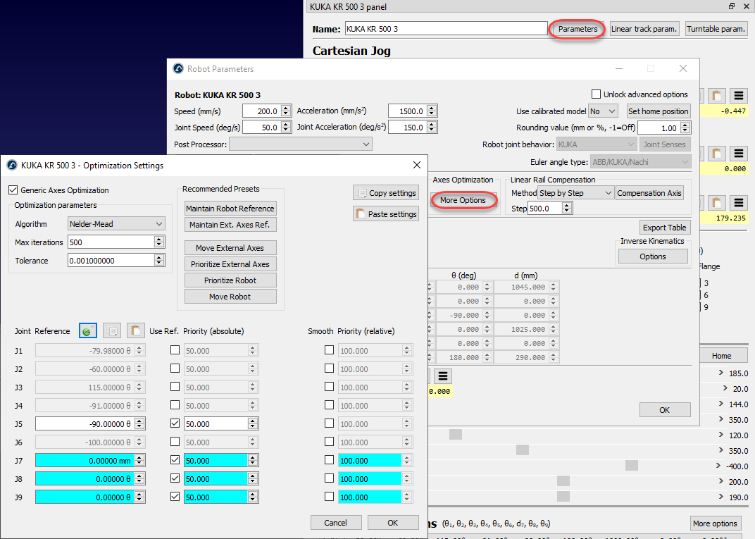
The variables can be retrieved or set as a dict or JSON string using the parameter/command OptimAxes as shown in the following example.
# This example shows how to read or modify the Axes Optimization settings using the RoboDK API and a JSON string.
# You can select "Axes optimization" in a robot machining menu or the robot parameters to view the axes optimization settings.
# It is possible to update the axes optimization settings attached to a robot or a robot machining project manually or using the API.
#
# More information about the RoboDK API here:
# https://robodk.com/doc/en/RoboDK-API.html
# For more information visit:
# https://robodk.com/doc/en/PythonAPI/robodk.html#robolink-py

from robodk.robolink import *  # RoboDK API
from robodk.robomath import *

# JSON tools
import json

# Start the RoboDK API
RDK = Robolink()

# Ask the user to select a robot arm (6 axis robot wich can have external axes)
robot = RDK.ItemUserPick("Select a robot arm", ITEM_TYPE_ROBOT_ARM)

# Default optimization settings test template
AxesOptimSettings = {
    # Optimization parameters:
    "Active": 1,  # Use generic axes optimization: 0=Disabled or 1=Enabled
    "Algorithm": 2,  # Optimization algorithm to use: 1=Nelder Mead, 2=Samples, 3=Samples+Nelder Mead
    "MaxIter": 650,  # Max. number of iterations
    "Tol": 0.0016,  # Tolerance to stop iterations

    # Absolute Reference joints (double):
    "AbsJnt_1": 104.17,
    "AbsJnt_2": 11.22,
    "AbsJnt_3": 15.97,
    "AbsJnt_4": -87.48,
    "AbsJnt_5": -75.36,
    "AbsJnt_6": 63.03,
    "AbsJnt_7": 174.13,
    "AbsJnt_8": 173.60,
    "AbsJnt_9": 0,

    # Using Absolute reference joints (0: No, 1: Yes):
    "AbsOn_1": 1,
    "AbsOn_2": 1,
    "AbsOn_3": 1,
    "AbsOn_4": 1,
    "AbsOn_5": 1,
    "AbsOn_6": 1,
    "AbsOn_7": 1,
    "AbsOn_8": 1,
    "AbsOn_9": 1,

    # Weight for absolute reference joints (double):
    "AbsW_1": 100,
    "AbsW_2": 100,
    "AbsW_3": 100,
    "AbsW_4": 89,
    "AbsW_5": 90,
    "AbsW_6": 92,
    "AbsW_7": 92,
    "AbsW_8": 96,
    "AbsW_9": 50,

    # Using for relative joint motion smoothing (0: No, 1: Yes):
    "RelOn_1": 1,
    "RelOn_2": 1,
    "RelOn_3": 1,
    "RelOn_4": 1,
    "RelOn_5": 1,
    "RelOn_6": 1,
    "RelOn_7": 1,
    "RelOn_8": 1,
    "RelOn_9": 1,

    # Weight for relative joint motion (double):
    "RelW_1": 5,
    "RelW_2": 47,
    "RelW_3": 44,
    "RelW_4": 43,
    "RelW_5": 36,
    "RelW_6": 47,
    "RelW_7": 53,
    "RelW_8": 59,
    "RelW_9": 0,
}

# Update one value, for example, make it active:
ToUpdate = {}
ToUpdate["Active"] = 1
json_str = json.dumps(ToUpdate)
status = robot.setParam("OptimAxes", json_str)
print(status)

# Example to make a partial or full update
count = 1
while True:
    for i in range(7):
        # Partial update
        ToUpdate = {}
        ToUpdate["AbsJnt_" + str(i + 1)] = (count + i) * 4
        ToUpdate["AbsOn_" + str(i + 1)] = count % 2
        ToUpdate["AbsW_" + str(i + 1)] = (count + i)

        json_str = json.dumps(ToUpdate)
        status = robot.setParam("OptimAxes", json_str)
        print(status)

        # Full update
        #OptimAxes_TEST["RefJoint_" + str(i+1)] = (count+i)*4
        #OptimAxes_TEST["RefWeight_" + str(i+1)] = (count+i)
        #OptimAxes_TEST["RefOn_" + str(i+1)] = count % 2

    # Full update
    #print(robot.setParam("OptimAxes", str(AxesOptimSettings)))
    count = count + 1

    # Read settings
    json_data = robot.setParam("OptimAxes")
    json_object = json.loads(json_data)
    print(json.dumps(json_object, indent=4))
    pause(0.2)

# Example to read the current axes optimization settings:
while True:
    json_data = robot.setParam("OptimAxes")
    json_object = json.loads(json_data)
    print(json.dumps(json_object, indent=4))
    pause(0.2)
6.26. Modify Program Instructions
This example shows how to retrieve modify program instructions using dictionaries. This example iterates over the selected program changing the speeds, and removing any pause instructions and adding custom program calls.
# This example shows how to modify program instructions
# See also:
# https://robodk.com/doc/en/PythonAPI/robodk.html#robodk.robolink.Robolink.AddProgram

from robodk.robolink import *  # API to communicate with RoboDK
import json

# Start the RoboDK API
RDK = Robolink()

# Ask the user to select a program:
prog = RDK.ItemUserPick("Select a Program to modify", ITEM_TYPE_PROGRAM)
if not prog.Valid():
    print("Operation cancelled or no programs available")
    quit()

# Ask the user to enter a function call that will be added after each movement:
print("Program selected: " + prog.Name())

# Iterate for all instructions (index start is 0, you can also use -1 for the last instruction)
ins_count = prog.InstructionCount()
ins_id = 0
while ins_id < ins_count:
    # Get specific data related to an instruction
    # This operation always retuns a dict (json)
    instruction_dict = prog.setParam(ins_id)

    # Print instruction data
    #indented_values = json.dumps(instruction_dict, indent=4)
    print("\n\nInstruction: " + str(ins_id))
    print(instruction_dict)

    # Note: The type is unique for each instruction and can't be changed.
    #    However, setting the Type value to -1 will delete the instruction (same as InstructionDelete())
    if instruction_dict['Type'] == INS_TYPE_CHANGESPEED:
        # Reduce speeds:
        newvalues = {'Speed': 50}
        if instruction_dict['Speed'] > 50:
            new_speed = 0.8 * instruction_dict['Speed']
            newvalues = {'Speed': new_speed}
            print("Reducing speed to: %.3f" % new_speed)

        # Update instruction data
        prog.setParam(ins_id, newvalues)
        # RoboDK may change the instruction name if you don't provide a new name

    elif instruction_dict['Type'] == INS_TYPE_CODE:
        # Select the movement instruction as a reference to add new instructions
        prog.InstructionSelect(ins_id)

        # Add a new program call
        prog.RunInstruction("Post" + instruction_dict['Code'], INSTRUCTION_CALL_PROGRAM)

        # Important: We just added a new instruction, so make sure we skip this instruction index!
        ins_id = ins_id + 1

    elif instruction_dict['Type'] == INS_TYPE_PAUSE:
        print("Deletint pause instruction")
        prog.InstructionDelete(ins_id)

        # Another way of deleting instructions:
        #delete_command = {'Type':-1}
        #prog.setParam(ins_id, delete_command)

        # Important: We just deleted an instruction, so make sure we recalculate our instruction index
        ins_id = ins_id - 1

    elif instruction_dict['Type'] == INS_TYPE_MOVE:
        print("Move instruction: use setInstruction to modify target")
        #ins_name, ins_type, move_type, isjointtarget, pose, joints = prog.Instruction(ins_id)
        #prog.setInstruction(ins_id, ins_name, ins_type, move_type, isjointtarget, pose, joints)

    ins_id = ins_id + 1

# Remove selection automatically created for new instructions
RDK.setSelection([])
You should see an output like this:
Instruction: 0
{'ForcePose': 0, 'FrameName': 'Part 1', 'FramePtr': '2256044235040', 'Name': 'Set Ref.: Part 1', 'Pose': 'transl(640.289,-290,0)*rotz(90)', 'Type': 3}
Instruction: 1
{'ForcePose': 0, 'Name': 'Set Tool: Spindle', 'Pose': 'transl(116.058,0,219.481)*roty(60)', 'ToolName': 'Spindle', 'ToolPtr': '2256296472848', 'Type': 4}
Instruction: 2
{'Joints': '40.166272,-71.394929,131.333329,60.014894,-40.159017,-30.066576', 'MoveType': 1, 'Name': 'MoveJ (Home)', 'Pose': 'transl(25,125,235)*rotx(180)*rotz(-90)', 'TargetPtr': '2256250820208', 'Type': 0}
Move instruction: use setInstruction to modify target
Instruction: 3
{'Message': 'Show message to user example', 'Name': 'Print: Show message to user example', 'Type': 9}
Instruction: 4
{'Accel': 3000, 'AccelSet': 0, 'JointAccel': 800, 'JointAccelSet': 0, 'JointSpeed': 500, 'JointSpeedSet': 0, 'Name': 'Set speed (100.0 mm/s)', 'Speed': 100, 'SpeedSet': 1, 'Type': 2}
Reducing speed to: 80.000
Instruction: 5
{'Behavior': 0, 'IO_Name': 'DO5', 'IO_Timeout': -1, 'IO_Value': '1', 'Name': 'Set DO5=1', 'Type': 11}
Instruction: 6
{'Behavior': 3, 'Code': 'Pause for 2 seconds', 'Name': 'Pause for 2 seconds', 'Type': 8}
Instruction: 8
{'Name': 'Pause 2.0 s', 'Pause': 2000, 'Type': 6}
Deletint pause instruction
Instruction: 8
{'Behavior': 1, 'IO_Name': 'DI2', 'IO_Timeout': -1, 'IO_Value': '1', 'Name': 'Wait DI2=1', 'Type': 11}
Instruction: 9
{'Joints': '9.438283,-44.942640,125.087243,9.577051,-80.279322,-1.631827', 'MoveType': 2, 'Name': 'MoveL (AppDrilling 1)', 'Pose': 'transl(25,25,35)*rotx(-180)*rotz(-90)', 'TargetPtr': '2256303988672', 'Type': 0}
Move instruction: use setInstruction to modify target
Instruction: 10
{'Behavior': 0, 'Code': 'SubProg1', 'Name': 'Call SubProg1', 'Type': 8}
Instruction: 12
{'Name': 'Smooth(2)', 'Rounding': 2, 'Type': 10}
Instruction: 13
{'Joints': '9.438283,-40.700206,124.039821,9.501249,-83.430178,-1.097016', 'MoveType': 2, 'Name': 'MoveL (Drilling 1)', 'Pose': 'transl(25,25,5)*rotx(-180)*rotz(-90)', 'TargetPtr': '2256250838928', 'Type': 0}
Move instruction: use setInstruction to modify target
Instruction: 14
{'Joints': '-57.379302,-35.838307,153.203991,-126.860991,-32.651850,-27.340520', 'MoveType': 2, 'Name': 'MoveL (Drilling 2)', 'Pose': 'transl(125,25,5)*rotx(-180)*rotz(-90)', 'TargetPtr': '2256250837056', 'Type': 0}
Move instruction: use setInstruction to modify target
6.27. Program Instruction Handling via API
The following commands and parameters allow for advanced manipulation of program instructions.
The setParam item function is a generic function that can be used to query or modify the state of instructions within a program.
Retrieve Selected Instructions: To get the indexes of currently selected instructions (returned as a comma-separated string):
selection = prog.setParam("Selection")
Update Selection: To select specific instructions by their indexes (e.g., selecting instructions 2 and 3):
prog.setParam("Selection", "1,2")
Retrieve the Running Instruction: To get the index of the instruction currently being executed:
ins_idx_running = prog.setParam("CurrentInstruction")
Start Execution from Index: To start a program from a specific instruction index, or to execute only a single instruction:
# Start running from instruction index ins_idx
prog.setParam("Start", ins_idx)

# Run only one specific instruction
prog.setParam("StartOne", ins_idx)
Retrieve Instruction as JSON: Returns a JSON dictionary containing all data related to the instruction at the specified index. Instructions can be handled as JSON objects, allowing for deep copying or modification of properties.
strjson = prog.setParam(ins_idx)
Add or Update instruction using JSON format: You can create a new instruction or update an existing one using a JSON dictionary.
# Example JSON structure
strjson = {"Name": name, "Type": insType, ...}

# Add a new instruction at the end of the program
prog.setParam("New", strjson)

# Update an existing instruction index
# Note: The instruction type must remain the same
prog.setParam(ins_idx, strjson)
Update Selection for API Operations: To set the insertion point for new instructions added via the API:
# Select the reference instruction
prog.InstructionSelect(instruction_id)

# The new instruction will be added after instruction_id
prog.RunInstruction("ProgramCall", INSTRUCTION_CALL_PROGRAM)
Reorder Instructions: Instructions can be moved within the same program or transferred to a different program using “Reorder Before” or “Reorder After”.
# Move instruction_id_from to before instruction_id_to within the same program:
prog.setParam("Reorder Before", str(instruction_id_from) + "|" + str(instruction_id_to))

# Move an instruction to a different program (program_to):
prog.setParam("Reorder Before", str(instruction_id_from) + "|" + str(instruction_id_to) + "|" + str(program_to.ptr))
Evaluate the pose of an instruction: Some instructions provide the pose as a string value (such as movements, set reference, set tool), you can convert the string to a pose using a function such as String2Pose:
def String2Pose(posestring):
        """Convert the pose as a string to a pose as a Matrix of type Mat"""
        from robodk import robomath
        import math
        context = {}
        context["transl"] = robomath.transl
        context["rotx"] = lambda rx: robomath.rotx(rx * math.pi / 180.0)
        context["roty"] = lambda ry: robomath.roty(ry * math.pi / 180.0)
        context["rotz"] = lambda rz: robomath.rotz(rz * math.pi / 180.0)
        # pose = eval("transl(100,0,0)*rotx(180)*roty(90)", context)
        pose = eval(posestring, context)
        return pose

pose = String2Pose(instruction["Pose"])
print(pose)
6.28. Retrieve selected geometry
This example shows how to retrieve surface or geometry selection by the user. It uses GetPoints and creates a new surface that highlights the selected object.
You can also use best fitting algorithms provided by RoboDK to know what type of geometry was selected (plane, cylinder, sphere, …).
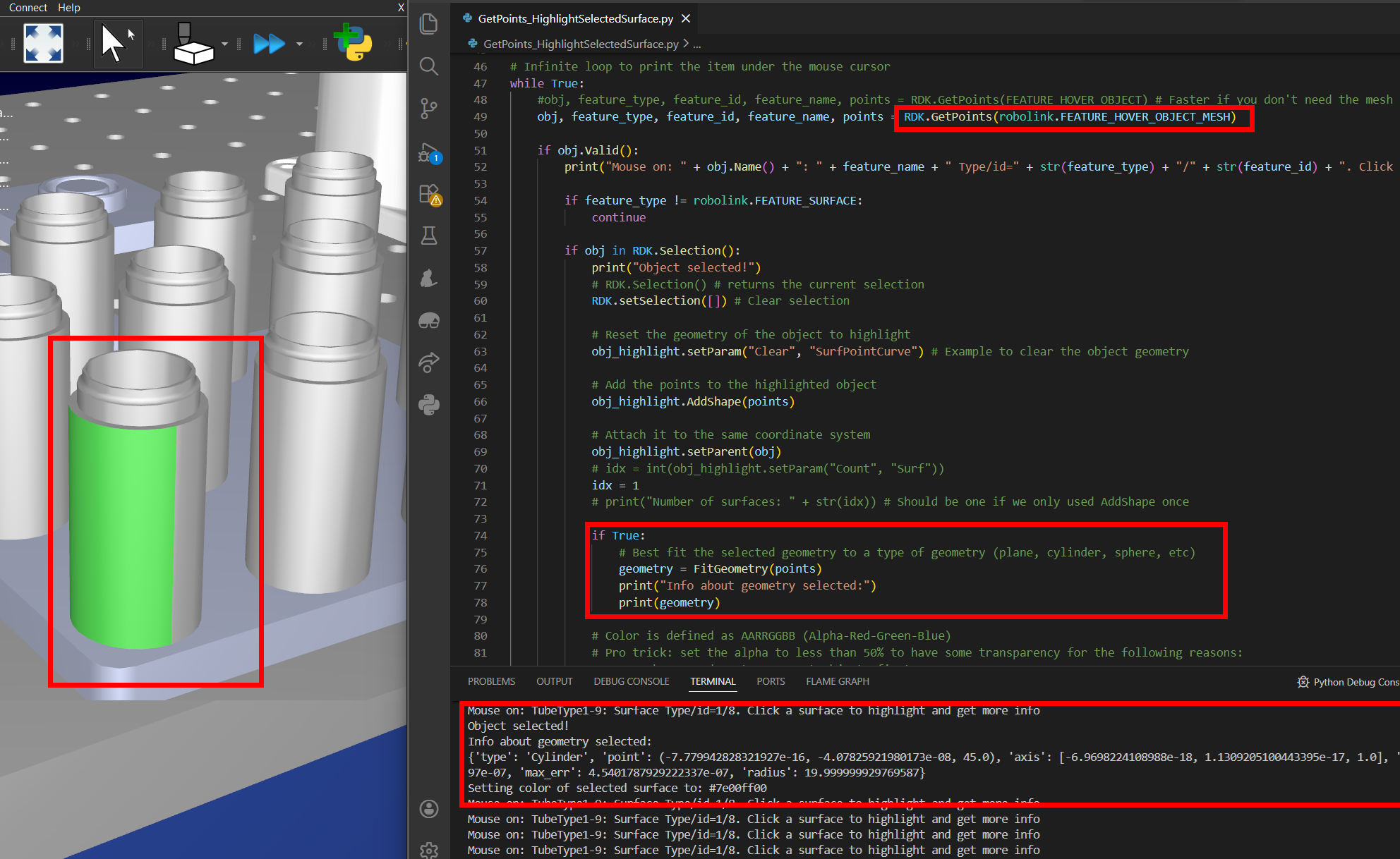
Run this script and select an object surface to see the type of feature that was selected.
# This example shows how to get a custom geometry selection by the user. It uses GetPoints and creates a new surfaces that highlights the selected object.
# You can also use best fitting algorithms provided by RoboDK to know what type of geometry was selected.

# Start the RoboDK API
from robodk import robolink    # RoboDK API
from robodk import robomath    # Robot toolbox
import time
RDK = robolink.Robolink()

# Use an empty and hidden object to hold selected geometry
obj_highlight = RDK.AddFile("")
obj_highlight.setName("API Object to highlight selection")
obj_highlight.setParam("Tree", "Hide") # Hide the object from the user (this won't be seen in the tree or saved)
obj_highlight.setParam("Clear", "SurfPointCurve") # Example to clear the object container items, including everything (surfaces, curves, points)

def FitGeometry(mesh):
    geo_types = ['Unknown', 'Plane', 'Cylinder', 'Sphere', 'Line', 'Point']

    # Convert the triangle mesh to a Mat object and trigger the best fitting algorithm provided by RoboDK API
    points_mat = robomath.Mat(mesh)[:, :3].tr()
    geometry = RDK.Command("FitGeometry", points_mat)

    # Retrieve the result
    g_data_list = geometry[0].list()
    if len(g_data_list) == 0:
        return None

    if len(g_data_list) < 9:
        return None

    g_data = {}
    g_data["type"] = geo_types[int(g_data_list[0])]
    g_data["point"] = tuple(g_data_list[1:4])  # Point on plane or point on cylinder axis (typically center point)
    g_data["axis"] = tuple(g_data_list[4:7])  # Plane normal or cylinder axis
    if True:
        # It should be normalized already, but just in case
        g_data["axis"] = robomath.normalize3(g_data["axis"])

    g_data["mean_err"] = float(g_data_list[7])
    g_data["max_err"] = float(g_data_list[8])
    if len(g_data_list) > 9:
        g_data["radius"] = float(g_data_list[9])

    return g_data

# Infinite loop to print the item under the mouse cursor
while True:
    #obj, feature_type, feature_id, feature_name, points = RDK.GetPoints(FEATURE_HOVER_OBJECT) # Faster if you don't need the mesh
    obj, feature_type, feature_id, feature_name, points = RDK.GetPoints(robolink.FEATURE_HOVER_OBJECT_MESH)

    if obj.Valid():
        print("Mouse on: " + obj.Name() + ": " + feature_name + " Type/id=" + str(feature_type) + "/" + str(feature_id) + ". Click a surface to highlight and get more info")

        if feature_type != robolink.FEATURE_SURFACE:
            continue

        if obj in RDK.Selection():
            print("Object selected!")
            # RDK.Selection() # returns the current selection
            RDK.setSelection([]) # Clear selection

            # Reset the geometry of the object to highlight
            obj_highlight.setParam("Clear", "SurfPointCurve") # Example to clear the object geometry

            # Add the points to the highlighted object
            obj_highlight.AddShape(points)

            # Attach it to the same coordinate system
            obj_highlight.setParent(obj)
            # idx = int(obj_highlight.setParam("Count", "Surf"))
            idx = 1
            # print("Number of surfaces: " + str(idx)) # Should be one if we only used AddShape once

            if True:
                # Best fit the selected geometry to a type of geometry (plane, cylinder, sphere, etc)
                geometry = FitGeometry(points)
                print("Info about geometry selected:")
                print(geometry)

            # Color is defined as AARRGGBB (Alpha-Red-Green-Blue)
            # Pro trick: set the alpha to less than 50% to have some transparency for the following reasons:
            #   1. RoboDK renders transparent objects first.
            #   2. We can not click through objects with less than 50% of transparency, this allows us to click the objects of the cell and not our highlighted objects
            color = "#7e00ff00"
            print("Setting color of selected surface to: " + color)
            result = obj_highlight.setParam("Color", color + " " + str(idx-1))

    else:
        print("Nothing under the mouse cursor")

    time.sleep(0.1)
6.29. Drawing an SVG image
A robot is programmed given an SVG image to simulate a drawing application. An ABB IRB 4600-20/2.50 is used in this example.
3D HTML simulation of this example: https://robodk.com/simulations/Robot-Drawing.html
# Type help("robolink") or help("robodk") for more information
# Press F5 to run the script
# Documentation: https://robodk.com/doc/en/RoboDK-API.html
# Reference:     https://robodk.com/doc/en/PythonAPI/index.html
#
# A robot is programmed given an SVG image to simulate a drawing application. An ABB IRB 4600-20/2.50 is used in this example.

from robodk.robolink import *  # API to communicate with RoboDK for simulation and offline/online programming
from robodk.robomath import *  # Robotics toolbox for industrial robots

import sys
import os
import re

#--------------------------------------------------------------------------------
# function definitions:


def point2D_2_pose(point, tangent):
    """Converts a 2D point to a 3D pose in the XY plane (4x4 homogeneous matrix)"""
    return transl(point.x, point.y, 0) * rotz(tangent.angle())


def svg_draw_quick(svg_img, board, pix_ref):
    """Quickly shows the image result without checking the robot movements."""
    RDK.Render(False)
    count = 0
    for path in svg_img:
        count = count + 1
        # use the pixel reference to set the path color, set pixel width and copy as a reference
        pix_ref.Recolor(path.fill_color)
        np = path.nPoints()
        print('drawing path %i/%i' % (count, len(svg_img)))
        for i in range(np):
            p_i = path.getPoint(i)
            v_i = path.getVector(i)
            pt_pose = point2D_2_pose(p_i, v_i)

            # add the pixel geometry to the drawing board object, at the calculated pixel pose
            board.AddGeometry(pix_ref, pt_pose)

    RDK.Render(True)


def svg_draw_robot(svg_img, board, pix_ref, item_frame, item_tool, robot):
    """Draws the image with the robot. It is slower that svg_draw_quick but it makes sure that the image can be drawn with the robot."""

    APPROACH = 100  # approach distance in MM for each path
    home_joints = [0, 0, 0, 0, 90, 0]  # home joints, in deg

    robot.setPoseFrame(item_frame)
    robot.setPoseTool(item_tool)
    robot.MoveJ(home_joints)

    # get the target orientation depending on the tool orientation at home position
    orient_frame2tool = invH(item_frame.Pose()) * robot.SolveFK(home_joints) * item_tool.Pose()
    orient_frame2tool[0:3, 3] = Mat([0, 0, 0])
    # alternative: orient_frame2tool = roty(pi)

    for path in svg_img:
        # use the pixel reference to set the path color, set pixel width and copy as a reference
        print('Drawing %s, RGB color = [%.3f,%.3f,%.3f]' % (path.idname, path.fill_color[0], path.fill_color[1], path.fill_color[2]))
        pix_ref.Recolor(path.fill_color)
        np = path.nPoints()

        # robot movement: approach to the first target
        p_0 = path.getPoint(0)
        target0 = transl(p_0.x, p_0.y, 0) * orient_frame2tool
        target0_app = target0 * transl(0, 0, -APPROACH)
        robot.MoveL(target0_app)
        RDK.RunMessage('Drawing %s' % path.idname)
        RDK.RunProgram('SetColorRGB(%.3f,%.3f,%.3f)' % (path.fill_color[0], path.fill_color[1], path.fill_color[2]))
        for i in range(np):
            p_i = path.getPoint(i)
            v_i = path.getVector(i)
            pt_pose = point2D_2_pose(p_i, v_i)

            # robot movement:
            target = transl(p_i.x, p_i.y, 0) * orient_frame2tool  #keep the tool orientation constant
            #target = pt_pose*orient_frame2tool #moving the tool along the path (axis 6 may reach its limits)
            robot.MoveL(target)

            # create a new pixel object with the calculated pixel pose
            board.AddGeometry(pix_ref, pt_pose)

        target_app = target * transl(0, 0, -APPROACH)
        robot.MoveL(target_app)

    robot.MoveL(home_joints)


#--------------------------------------------------------------------------------
# Program start
RDK = Robolink()

# locate and import the svgpy module
path_stationfile = RDK.getParam('PATH_OPENSTATION')
sys.path.append(os.path.abspath(path_stationfile))  # temporary add path to import station modules
from svgpy.svg import *

# select the file to draw
svgfile = path_stationfile + '/World map.svg'
#svgfile = path_stationfile + '/RoboDK text.svg'

# import the SVG file
svgdata = svg_load(svgfile)

IMAGE_SIZE = Point(1000, 2000)  # size of the image in MM
MM_X_PIXEL = 10  # in mm the path will be cut is depending on the pixel size
svgdata.calc_polygon_fit(IMAGE_SIZE, MM_X_PIXEL)
size_img = svgdata.size_poly()  # returns the size of the current polygon

# get the robot, frame and tool objects
robot = RDK.Item('ABB IRB 4600-20/2.50')
framedraw = RDK.Item('Frame draw')
tooldraw = RDK.Item('Tool')

# get the pixel reference to draw
pixel_ref = RDK.Item('pixel')

# delete previous image if any
image = RDK.Item('Board & image')
if image.Valid() and image.Type() == ITEM_TYPE_OBJECT:
    image.Delete()

# make a drawing board base on the object reference "Blackboard 250mm"
board_1m = RDK.Item('Blackboard 250mm')
board_1m.Copy()
board_draw = framedraw.Paste()
board_draw.setName('Board & image')
board_draw.Scale([size_img.x / 250, size_img.y / 250, 1])  # adjust the board size to the image size (scale)

# quickly show the final result without checking the robot movements:
#svg_draw_quick(svgdata, board_draw, pixel_ref)

# draw the image with the robot:
svg_draw_robot(svgdata, board_draw, pixel_ref, framedraw, tooldraw, robot)
6.30. Synchronize 3 Robots
This example shows to synchronize multiple robots at the same time. The robots can be synchronized together given keypoints and using Python threads. This example is similar to Offline Programming but updated to support moving multiple robots at the same time. The robots can be connected to the computer using appropriate robot drivers and switch from the simulation to moving the real robots.
# Type help("robolink") or help("robodk") for more information
# Press F5 to run the script
# Documentation: https://robodk.com/doc/en/RoboDK-API.html
# Reference:     https://robodk.com/doc/en/PythonAPI/index.html
#
# This example shows to synchronize multiple robots at the same time

from robodk.robolink import *  # API to communicate with RoboDK for offline/online programming
from robodk.robomath import *  # Robot toolbox

import threading
import queue
import time

#----------------------------------------------
# Function definitions and global variable declarations

# Global variables used to synchronize the robot movements
# These variables are managed by SyncSet() and SynchWait()

SYNC_COUNT = 0
SYNC_TOTAL = 0
SYNC_ID = 0
lock = threading.Lock()


def SyncSet(total_sync):
    """SyncSet will set the number of total robot programs (threads) that must be synchronized togeter.
    Every time SyncSet is called SYNC_ID is increased by one."""
    global SYNC_COUNT
    global SYNC_TOTAL
    global SYNC_ID
    with lock:
        SYNC_COUNT = 0
        SYNC_TOTAL = total_sync
        SYNC_ID = SYNC_ID + 1
        #print('SyncSet')


def SyncWait():
    """SyncWait will block the robot movements for a robot when necessary, synchronizing the movements sequentially.
    Use SyncSet(nrobots) to define how many robots must be synchronized together."""
    global SYNC_COUNT
    # Save a local variable with the sync event id
    sync_id = SYNC_ID
    with lock:
        # Increase the number of threads that are synchronized
        SYNC_COUNT += 1

    # Move to the next sync event if all threads reached the SyncWait (SYNC_COUNT = SYNC_TOTAL)
    if SYNC_COUNT >= SYNC_TOTAL:
        SyncSet(SYNC_TOTAL)
        return

    # Wait for a SynchSet to move forward
    while sync_id >= SYNC_ID:
        time.sleep(0.0001)


# Main procedure to move each robot
def DoWeld(q, robotname):
    # Any interaction with RoboDK must be done through Robolink()
    # Each robot movement requires a new Robolink() object (new link of communication).
    # Two robots can't be moved by the same communication link.

    rdk = Robolink()

    # get the robot item:
    robot = rdk.Item(robotname)

    # get the home joints target
    home = robot.JointsHome()

    # get the reference welding target:
    target = rdk.Item('Target')

    # get the reference frame and set it to the robot
    reference = target.Parent()
    robot.setPoseFrame(reference)

    # get the pose of the target (4x4 matrix):
    poseref = target.Pose()
    pose_approach = poseref * transl(0, 0, -100)

    # move the robot to home, then to the center:
    robot.MoveJ(home)
    robot.MoveJ(pose_approach)
    SyncWait()
    robot.MoveL(target)

    # make an hexagon around the center:
    for i in range(7):
        ang = i * 2 * pi / 6  #angle: 0, 60, 120, ...
        posei = poseref * rotz(ang) * transl(200, 0, 0) * rotz(-ang)
        SyncWait()
        robot.MoveL(posei)

    # move back to the center, then home:
    SyncWait()
    robot.MoveL(target)
    robot.MoveL(pose_approach)
    robot.MoveJ(home)
    q.put('Robot %s finished' % robotname)


#----------------------------------------
# Python program start

# retrieve all available robots in the RoboDK station (as a list of names)
RDK = Robolink()
robots = RDK.ItemList(ITEM_TYPE_ROBOT)
print(robots)

# retrieve the number of robots to synchronize together
nrobots = len(robots)
SyncSet(nrobots)

# the queue allows sharing messages between threads
q = queue.Queue()

# Start the DoWeld program for all robots. Each robot will run on a separate thread.
threads = []
for i in range(nrobots):
    robotname = robots[i]
    t = threading.Thread(target=DoWeld, args=(q, robotname))
    t.daemon = True
    t.start()
    threads.append(t)

# wait for every thead to finish
for x in threads:
    x.join()
    print(q.get())

print('Main program finished')
6.31. Robot Model (DH)
This example models the forward and inverse kinematics of an ABB IRB 120 robot using the RoboDK API for Python. Reference frames are placed according to an existing robot in the station.
# Type help("robolink") or help("robodk") for more information
# Press F5 to run the script
# Documentation: https://robodk.com/doc/en/RoboDK-API.html
# Reference:     https://robodk.com/doc/en/PythonAPI/index.html
#
# This example models the forward and inverse kinematics of an ABB IRB 120 robot using the RoboDK API for Python

from robodk.robolink import *  # API to communicate with RoboDK for simulation and offline/online programming
from robodk.robomath import *  # Robot toolbox

#----------------------------------------------
# Function definitions


def FK_Robot(dh_table, joints):
    """Computes the forward kinematics of the robot.
    dh_table must be in mm and radians, the joints array must be given in degrees."""
    Habs = []
    Hrel = []
    nlinks = len(dh_table)
    HiAbs = eye(4)
    for i in range(nlinks):
        [rz, tx, tz, rx] = dh_table[i]
        rz = rz + joints[i] * pi / 180
        Hi = dh(rz, tx, tz, rx)
        HiAbs = HiAbs * Hi
        Hrel.append(Hi)
        Habs.append(HiAbs)

    return [HiAbs, Habs, Hrel]


def Frames_setup_absolute(frameparent, nframes):
    """Adds nframes reference frames to frameparent"""
    frames = []
    for i in range(nframes):
        newframe = frameparent.RDK().AddFrame('frame %i' % (i + 1), frameparent)
        newframe.setPose(transl(0, 0, 100 * i))
        frames.append(newframe)

    return frames


def Frames_setup_relative(frameparent, nframes):
    """Adds nframes reference frames cascaded to frameparent"""
    frames = []
    parent = frameparent
    for i in range(nframes):
        newframe = frameparent.RDK().AddFrame('frame %i' % (i + 1), parent)
        parent = newframe
        newframe.setPose(transl(0, 0, 100))
        frames.append(newframe)

    return frames


def Set_Items_Pose(itemlist, poselist):
    """Sets the pose (3D position) of each item in itemlist"""
    for item, pose in zip(itemlist, poselist):
        item.setPose(pose)


def are_equal(j1, j2):
    """Returns True if j1 and j2 are equal, False otherwise"""
    if j1 is None or j2 is None:
        return False
    sum_diffs_abs = sum(abs(a - b) for a, b in zip(j1, j2))
    if sum_diffs_abs > 1e-3:
        return False
    return True


#----------------------------------------------------------
# The program starts here:
RDK = Robolink()

#-----------------------------------------------------
# DH table of the robot: ABB IRB 120-3/0.6
DH_Table = []
#                 rZ (theta),   tX,   tZ,   rX (alpha)
DH_Table.append([0, 0, 290, -90 * pi / 180])
DH_Table.append([-90 * pi / 180, 270, 0, 0])
DH_Table.append([0, 70, 0, -90 * pi / 180])
DH_Table.append([0, 0, 302, 90 * pi / 180])
DH_Table.append([0, 0, 0, -90 * pi / 180])
DH_Table.append([180 * pi / 180, 0, 72, 0])

# degrees of freedom: (6 for ABB IRB 120-3/0.6)
DOFs = len(DH_Table)

# get the robot:
robot = RDK.Item('ABB IRB 120-3/0.6')

# cleanup of all items containing "Mirror tests" from previous tests
while True:
    todelete = RDK.Item('Robot base')
    # make sure an item was found
    if not todelete.Valid():
        break
    # delete only frames
    if todelete.Type() == ITEM_TYPE_FRAME:
        print('Deleting: ' + todelete.Name())
        todelete.Delete()

# setup the parent frames for the test:
parent_frameabs = RDK.AddFrame('Robot base (absolute frames)')
parent_framerel = RDK.AddFrame('Robot base (relative frames)')

# setup the child frames for the test:
frames_abs = Frames_setup_absolute(parent_frameabs, DOFs)
frames_rel = Frames_setup_relative(parent_framerel, DOFs)

# remember the last robot joints to update when necessary
last_joints = None

# infinite loop
while True:
    # get the current robot joints as a float array (list)
    joints = robot.Joints().tolist()

    # do not update if joints are the same as before
    if are_equal(joints, last_joints):
        continue

    # if joints changed, compute the forward kinematics for this position
    [Hrobot, HabsList, HrelList] = FK_Robot(DH_Table, joints)

    # turn off rendering while we update all frames:
    RDK.Render(False)
    # update all frames
    Set_Items_Pose(frames_abs, HabsList)
    Set_Items_Pose(frames_rel, HrelList)

    # render and turn on rendering
    RDK.Render(True)

    # remember the last robot joints
    last_joints = joints

    print('Current robot joints:')
    print(joints)
    print('Pose of the robot (forward kinematics):')
    print(Hrobot)
    print('\n\n')
6.32. Camera (2D)
6.32.1. Camera Live Stream
This example demonstrates some of the basic functionalities to manage 2D cameras using the RoboDK API for Python. It creates or reuse an existing camera, set its parameters, get the image using two different methods and display it to the user as a live stream. This is a great starting point for your computer vision algorithms.
# Type help("robodk.robolink") or help("robodk.robomath") for more information
# Press F5 to run the script
# Documentation: https://robodk.com/doc/en/RoboDK-API.html
# Reference:     https://robodk.com/doc/en/PythonAPI/index.html
#
# This example demonstrates some of the basic functionalities to handle 2D cameras using the RoboDK API for Python.
# It creates/reuses an existing camera, set its parameters, get the image using two different methods and display it to the user as a live stream.
# This is a great starting point for your computer vision algorithms.
#

from robodk import robolink  # RoboDK API
from robodk import robomath  # Robot toolbox
RDK = robolink.Robolink()

# OpenCV is an open source Computer Vision toolkit, which you can use to filter and analyse images
robolink.import_install('cv2', 'opencv-python', RDK)
robolink.import_install('numpy', RDK)
import numpy as np
import cv2 as cv

CAM_NAME = 'My Camera'
CAM_PARAMS = 'SIZE=640x480' # For more options, see https://robodk.com/doc/en/PythonAPI/robodk.html#robodk.robolink.Robolink.Cam2D_Add
WINDOW_NAME = 'My Camera Feed'

#----------------------------------
# Get the camera item
cam_item = RDK.Item(CAM_NAME, robolink.ITEM_TYPE_CAMERA)
if not cam_item.Valid():
    cam_item = RDK.Cam2D_Add(RDK.AddFrame(CAM_NAME + ' Frame'), CAM_PARAMS)
    cam_item.setName(CAM_NAME)
cam_item.setParam('Open', 1)

#----------------------------------
# Create a live feed
while cam_item.setParam('isOpen') == '1':

    #----------------------------------
    # Method 1: Get the camera image, by socket
    img_socket = None
    bytes_img = RDK.Cam2D_Snapshot('', cam_item)
    if isinstance(bytes_img, bytes) and bytes_img != b'':
        nparr = np.frombuffer(bytes_img, np.uint8)
        img_socket = cv.imdecode(nparr, cv.IMREAD_COLOR)
    if img_socket is None:
        break

    #----------------------------------
    # Method 2: Get the camera image, from disk
    img_png = None
    import tempfile
    with tempfile.TemporaryDirectory(prefix='robodk_') as td:
        tf = td + '/temp.png'
        if RDK.Cam2D_Snapshot(tf, cam_item) == 1:
            img_png = cv.imread(tf)
    if img_png is None:
        break

    #----------------------------------
    # Show it to the world!
    cv.imshow(WINDOW_NAME, img_socket)
    key = cv.waitKey(1)
    if key == 27:
        break  # User pressed ESC, exit
    if cv.getWindowProperty(WINDOW_NAME, cv.WND_PROP_VISIBLE) < 1:
        break  # User killed the main window, exit

# Close the preview and the camera. Ensure you call cam_item.setParam('Open', 1) before reusing a camera!
cv.destroyAllWindows()
RDK.Cam2D_Close(cam_item)
6.32.2. Camera calibration
This example shows how to find a camera intrinsic properties using OpenCV. Print the chessboard and take a series of at least 5 images while moving the chessboard around. You can find more information in this OpenCV calibration tutorial.
# Type help("robolink") or help("robodk") for more information
# Press F5 to run the script
# Documentation: https://robodk.com/doc/en/RoboDK-API.html
# Reference:     https://robodk.com/doc/en/PythonAPI/index.html
#
# Find a camera intrinsic and extrinsic properties using a chessboard and a series of images.
# More details on camera calibration: https://docs.opencv.org/master/dc/dbb/tutorial_py_calibration.html
# You can print this board in letter format: https://github.com/opencv/opencv/blob/master/doc/pattern.png

from robodk.robolink import *
from robodk.robodialogs import *
import cv2 as cv
import numpy as np
import glob

#----------------------------------------------
# You can edit these settings for your board
SQUARES_X = 10  # number of squares along the X axis
SQUARES_Y = 7  # number of squares along the Y axis
PATTERN = (SQUARES_X - 1, SQUARES_Y - 1)
SQUARE_LENGTH = 23.0  # mm, length of one square

#----------------------------------------------
# Get the images
images_dir = getSaveFolder(popup_msg='Select the directory of the images')
images = glob.glob('%s/*.png' % images_dir) + glob.glob('%s/*.jpg' % images_dir)

#----------------------------------------------
# Parse the images
frame_size = None
obj_points = []  # 3D points in real world space
img_points = []  # 2D points in image plane.
objp = np.zeros((PATTERN[0] * PATTERN[1], 3), np.float32)  # object points (0,0,0), (1,0,0), (2,0,0) ....,(8,5,0)
objp[:, :2] = np.mgrid[0:PATTERN[0], 0:PATTERN[1]].T.reshape(-1, 2) * SQUARE_LENGTH

for image in images:
    # Read the image as grayscale
    img = cv.imread(image)
    gray = cv.cvtColor(img, cv.COLOR_BGR2GRAY)
    frame_size = gray.shape[::-1]

    # Find the chessboard corners
    ret, corners = cv.findChessboardCorners(gray, PATTERN, None)

    # If found, add object points, image points (after refining them)
    if ret == True:
        rcorners = cv.cornerSubPix(gray, corners, (11, 11), (-1, -1), (cv.TERM_CRITERIA_EPS + cv.TERM_CRITERIA_MAX_ITER, 30, 0.001))
        img_points.append(rcorners)
        obj_points.append(objp)

        # Draw and display the corners
        cv.drawChessboardCorners(img, PATTERN, rcorners, ret)
        cv.imshow('Original image', img)
        cv.waitKey(250)

cv.destroyAllWindows()

#----------------------------------------------
# Get the calibrated camera parameters
rms_err, calib_mtx, dist_coeffs, rvecs, tvecs = cv.calibrateCamera(obj_points, img_points, frame_size, None, None)
print('Overall RMS re-projection error: %0.3f' % rms_err)

#----------------------------------------------
# Save the parameters
file = getSaveFileName(strfile='RoboDK-Camera-Settings.yaml', defaultextension='.yaml', filetypes=[('YAML files', '.yaml')])
cv_file = cv.FileStorage(file, cv.FILE_STORAGE_WRITE)
if not cv_file.isOpened():
    raise Exception('Failed to save calibration file')
cv_file.write("camera_matrix", calib_mtx)
cv_file.write("dist_coeff", dist_coeffs)
cv_file.write("camera_size", frame_size)
cv_file.release()
6.32.3. Camera hand-eye calibration
Hand-eye calibration is the process of determining the camera “eye” position with respect to the robot flange or tool using OpenCV. The scripts provided in this example will help you collect the required data to perform hand-eye calibration. You will need a chessboard (checkerboard) or charucoboard to perform the calibration.
Although the tools provided are for online programming (the camera and the robot are connected to your computer and accessed by RoboDK), you can still adapt these scripts to perform it offline.
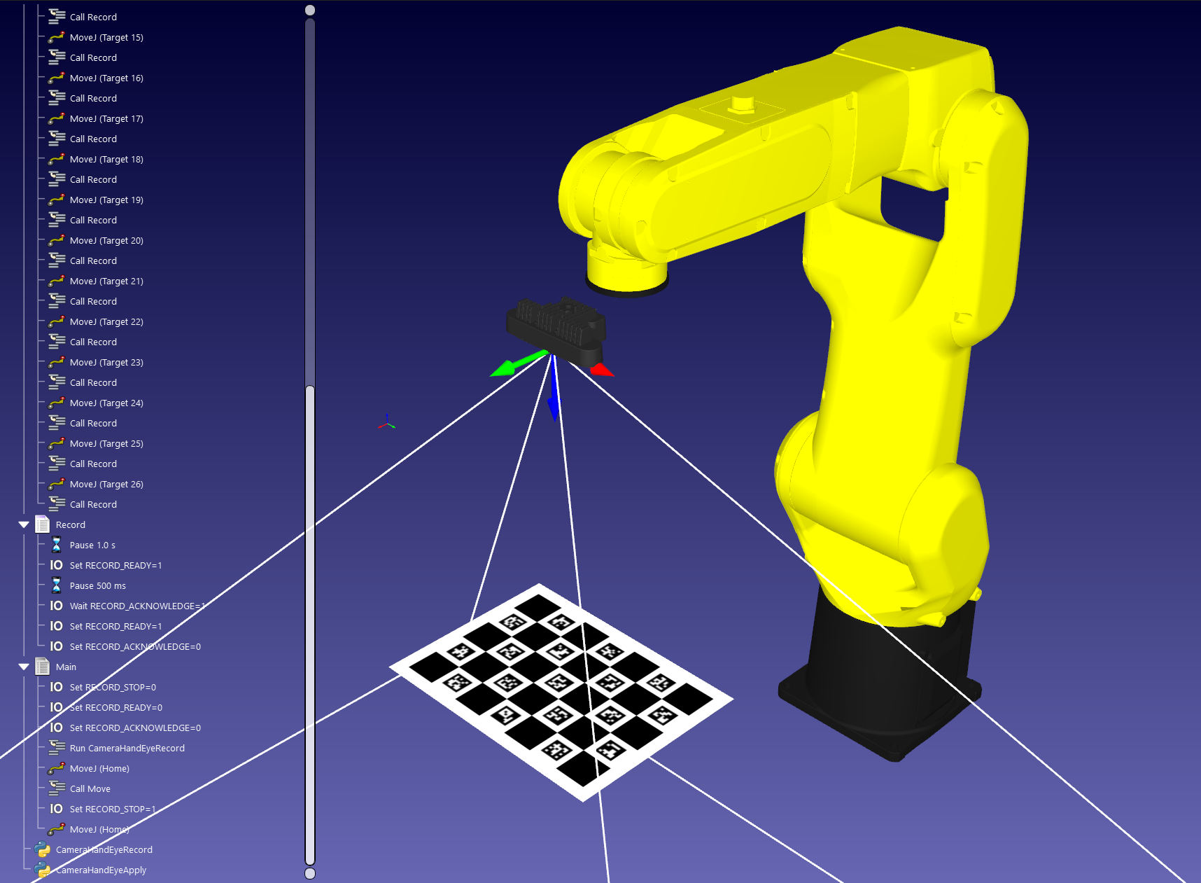
The first script is the acquisition script. Add it to your RoboDK station and launch it from your main program in a separate thread. Using IOs, you can trigger the recording of the robot pose and the camera (see the image below). Robot poses and images are saved on disk as JSON and PNG files with a matching ID. If you use another camera system, you can disable the camera acquisition and only record the robot poses.
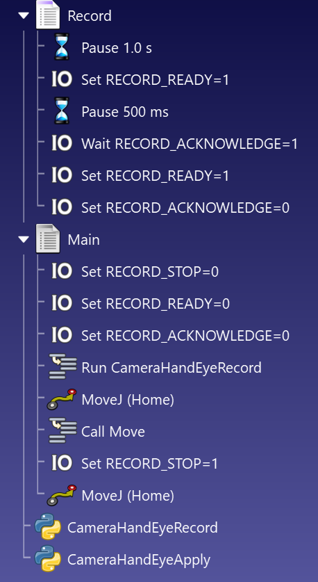
# Type help("robolink") or help("robodk") for more information
# Press F5 to run the script
# Documentation: https://robodk.com/doc/en/RoboDK-API.html
# Reference:     https://robodk.com/doc/en/PythonAPI/index.html
#
# Utility script to perform hand-eye calibration on a 2D camera.
# This script can be use for eye-in-hand or eye-to-hand calibrations.
# Dynamically record the robot pose and save the camera image on disk for later processing.
# This script is running in a separate thread and a main program request punctual recordings through an handshake.

from robodk import robolink  # RoboDK API
from robodk import robomath  # Robot toolbox

# Uncomment these lines to automatically install the dependencies using pip
# robolink.import_install('cv2', 'opencv-contrib-python==4.5.*')
# robolink.import_install('numpy')
import cv2 as cv
import numpy as np
from pathlib import Path
import json
from enum import Enum
import time


#--------------------------------------
# This script supports RoboDK virtual/simulated cameras, and USB devices (as supported by OpenCV)
# You can add your own implementation to retrieve images from any camera, such as a Cognex Insight, SICK, etc.
class CameraTypes(Enum):
    ROBODK_SIMULATED = 0
    OPENCV_USB = 1


RECORD_ROBOT = True  # Record the robot pose on disk
RECORD_CAMERA = True  # Record the camera image on disk
RECORD_FOLDER = 'Hand-Eye-Data'  # Default folder to save recordings, relative to the station folder

CAMERA_TYPE = CameraTypes.ROBODK_SIMULATED  # Camera type to be used
CAMERA_ROBODK_NAME = ''  # [Optional] Default name to use for the RoboDK camera
ROBOT_NAME = ''  # [Optional] Default name to use for the robot

# Station variables shared with the main program to interact with this script
RECORD_READY = 'RECORD_READY'  # Set this true in the main program when the robot is in position and the the script is allowed to record the robot and the image
RECORD_ACKNOWLEDGE = 'RECORD_ACKNOWLEDGE'  # Set this true in this script when the record is complete
RECORD_STOP = 'RECORD_STOP'  # Request to stop the script by the main program


#--------------------------------------
def get_robot(RDK: robolink.Robolink, robot_name: str):

    # Retrieve the robot
    robot_item = None
    if robot_name:
        robot_item = RDK.Item(robot_name, robolink.ITEM_TYPE_ROBOT)
        if not robot_item.Valid():
            robot_name = ''

    if not robot_name:
        robot_item = RDK.ItemUserPick("Select the robot for hand-eye", robolink.ITEM_TYPE_ROBOT)
        if not robot_item.Valid():
            raise

    return robot_item


def get_camera_handle(camera_type: CameraTypes, camera_name: str, RDK: robolink.Robolink):

    if camera_type == CameraTypes.ROBODK_SIMULATED:

        # Retrieve the RoboDK camera by name
        camera_item = None
        if camera_name:
            camera_item = RDK.Item(camera_name, robolink.ITEM_TYPE_CAMERA)
            if not camera_item.Valid():
                camera_name = ''

        if not camera_name:
            camera_item = RDK.ItemUserPick("Select the camera for hand-eye", robolink.ITEM_TYPE_CAMERA)
            if not camera_item.Valid():
                raise

        # Ensure the preview window in RoboDK is open
        if camera_item.setParam('Open') != '1':
            camera_item.setParam('Open', 1)
            robomath.pause(0.1)

        return camera_item

    elif camera_type == CameraTypes.OPENCV_USB:
        return cv.VideoCapture(0, cv.CAP_ANY)  # More information on supported devices here: https://docs.opencv.org/4.x/d8/dfe/classcv_1_1VideoCapture.html#aabce0d83aa0da9af802455e8cf5fd181

    return None


def record_camera(camera_type: CameraTypes, camera_handle, filename: str):
    if camera_type == CameraTypes.ROBODK_SIMULATED:
        record_robodk_camera(filename, camera_handle)

    elif camera_type == CameraTypes.OPENCV_USB:
        record_opencv_camera(filename, camera_handle)


def record_robodk_camera(filename: str, camera_item: robolink.Item):

    # Retrieve the image by socket
    bytes_img = camera_item.RDK().Cam2D_Snapshot('', camera_item)
    nparr = np.frombuffer(bytes_img, np.uint8)
    img = cv.imdecode(nparr, cv.IMREAD_COLOR)

    # Save the image on disk as a grayscale image
    cv.imwrite(filename, cv.cvtColor(img, cv.COLOR_RGB2GRAY))


def record_opencv_camera(filename: str, capture: cv.VideoCapture):

    # Retrieve image
    success, img = capture.read()
    if not success:
        raise

    # Save the image on disk as a grayscale image
    cv.imwrite(filename, cv.cvtColor(img, cv.COLOR_RGB2GRAY))


def record_robot(robot_item: robolink.Item, filename: str):

    # Retrieve the required information for hand-eye
    robot_data = {}
    robot_data['joints'] = robot_item.Joints().tolist()
    robot_data['pose_flange'] = robomath.Pose_2_TxyzRxyz(robot_item.SolveFK(robot_item.Joints()))

    # Save it on disk as a JSON
    # You can also provide another format, like YAML
    with open(filename, 'w') as f:
        json.dump(robot_data, f, indent=2)


def runmain():

    RDK = robolink.Robolink()

    # Retrieve the camera and robot
    camera_handle = get_camera_handle(CAMERA_TYPE, CAMERA_ROBODK_NAME, RDK)
    robot_item = get_robot(RDK, ROBOT_NAME)

    # Retrieve the folder to save the data
    record_folder = Path(RDK.getParam(robolink.PATH_OPENSTATION)) / RECORD_FOLDER
    record_folder.mkdir(exist_ok=True, parents=True)

    # This script does not delete the previous run if the folder is not empty
    # If the folder is not empty, retrieve the next ID
    id = 0
    ids = sorted([int(x.stem) for x in record_folder.glob('*.png') if x.stem.isdigit()])
    if ids:
        id = ids[-1] + 1

    # Start the main loop, and wait for requests
    RDK.setParam(RECORD_READY, 0)

    while True:
        time.sleep(0.01)

        # Read the requests set by the main program
        ready = int(RDK.getParam(RECORD_READY)) == 1
        stop = int(RDK.getParam(RECORD_STOP)) == 1
        if stop:
            break

        if not ready:
            continue

        # Process the requests
        if RECORD_CAMERA:
            img_filename = Path(f'{record_folder.as_posix()}/{id}.png')
            record_camera(CAMERA_TYPE, camera_handle, img_filename.as_posix())

        if RECORD_ROBOT:
            robot_filename = Path(f'{record_folder.as_posix()}/{id}.json')
            record_robot(robot_item, robot_filename.as_posix())

        id += 1

        # Inform the main program that we have completed the request
        RDK.setParam(RECORD_ACKNOWLEDGE, 1)
        RDK.setParam(RECORD_READY, 0)


if __name__ == '__main__':
    runmain()
The second script is the hand-eye calibration script. You can run it separately in your IDE or by adding it to your station. A dialog will open to retrieve the images and robot poses acquired by the previous script. The hand-eye calibration can then by applied to the selected tool (we recommend applying the hand-eye calibration to a new tool). Note that this is for eye-in-hand calibration (robot is holding the camera), but it can be easily adapted for eye-to-hand (static camera pointing to the robot).
# Type help("robolink") or help("robodk") for more information
# Press F5 to run the script
# Documentation: https://robodk.com/doc/en/RoboDK-API.html
# Reference:     https://robodk.com/doc/en/PythonAPI/index.html
#
# Perform hand-eye calibration with recorded robot poses and 2D images from disk.
# - Requires at least 8 different poses at different orientations/distances of a chessboard or charucoboard.
# - Requires a calibrated camera (known intrinsic parameters, including distortion), which can also be performed from local images.
#
# You can find the board used in this example here:
# https://docs.opencv.org/4.x/charucoboard.png
#

from robodk import robolink  # RoboDK API
from robodk import robomath  # Robot toolbox
from robodk import robodialogs  # Dialogs

# Uncomment these lines to automatically install the dependencies using pip
# robolink.import_install('cv2', 'opencv-contrib-python==4.5.*')
# robolink.import_install('numpy')
import cv2 as cv
import numpy as np
import json
from pathlib import Path
from enum import Enum


#--------------------------------------
# This scripts supports chessboard (checkerboard) and ChAruCo board as calibration objects.
# You can add your own implementation (such as dot patterns).
class MarkerTypes(Enum):
    CHESSBOARD = 0
    CHARUCOBOARD = 1


# The camera intrinsic parameters can be performed with the same board as the Hand-eye
INTRINSIC_FOLDER = 'Hand-Eye-Data'  # Default folder to load images for the camera calibration, relative to the station folder
HANDEYE_FOLDER = 'Hand-Eye-Data'  # Default folder to load robot poses and images for the hand-eye calibration, relative to the station folder

# Camera intrinsic calibration board parameters
# You can find this chessboard here: https://docs.opencv.org/4.x/charucoboard.png
INTRINSIC_BOARD_TYPE = MarkerTypes.CHESSBOARD
INTRINSIC_CHESS_SIZE = (5, 7)  # X/Y
INTRINSIC_SQUARE_SIZE = 35  # mm
INTRINSIC_MARKER_SIZE = 21  # mm

# Hand-eye calibration board parameters
# You can find this charucoboard here: https://docs.opencv.org/4.x/charucoboard.png
HANDEYE_BOARD_TYPE = MarkerTypes.CHARUCOBOARD
HANDEYE_CHESS_SIZE = (5, 7)  # X/Y
HANDEYE_SQUARE_SIZE = 35  # mm
HANDEYE_MARKER_SIZE = 21  # mm


def pose_2_Rt(pose: robomath.Mat):
    """RoboDK pose to OpenCV pose"""
    pose_inv = pose.inv()
    R = np.array(pose_inv.Rot33())
    t = np.array(pose.Pos())
    return R, t


def Rt_2_pose(R, t):
    """OpenCV pose to RoboDK pose"""
    vx, vy, vz = R.tolist()

    cam_pose = robomath.eye(4)
    cam_pose.setPos([0, 0, 0])
    cam_pose.setVX(vx)
    cam_pose.setVY(vy)
    cam_pose.setVZ(vz)

    pose = cam_pose.inv()
    pose.setPos(t.tolist())

    return pose


def find_chessboard(img, mtx, dist, chess_size, squares_edge, refine=True, draw_img=None):
    """
    Detects a chessboard pattern in an image.
    """

    pattern = np.subtract(chess_size, (1, 1))  # number of corners

    # Prefer grayscale images
    _img = img
    if len(img.shape) > 2:
        _img = cv.cvtColor(img, cv.COLOR_RGB2GRAY)

    # Find the chessboard's corners
    success, corners = cv.findChessboardCorners(_img, pattern)
    if not success:
        raise Exception("No chessboard found")

    # Refine
    if refine:
        criteria = (cv.TERM_CRITERIA_EPS + cv.TERM_CRITERIA_MAX_ITER, 30, 0.001)
        search_size = (11, 11)
        zero_size = (-1, -1)
        corners = cv.cornerSubPix(_img, corners, search_size, zero_size, criteria)

    if draw_img is not None:
        cv.drawChessboardCorners(draw_img, pattern, corners, success)

    # Find the camera pose. Only available with the camera matrix!
    if mtx is None or dist is None:
        return corners, None, None

    cb_corners = np.zeros((pattern[0] * pattern[1], 3), np.float32)
    cb_corners[:, :2] = np.mgrid[0:pattern[0], 0:pattern[1]].T.reshape(-1, 2) * squares_edge
    success, rvec, tvec = cv.solvePnP(cb_corners, corners, mtx, dist)
    if not success:
        raise Exception("No chessboard found")

    R_target2cam = cv.Rodrigues(rvec)[0]
    t_target2cam = tvec

    return corners, R_target2cam, t_target2cam


def find_charucoboard(img, mtx, dist, chess_size, squares_edge, markers_edge, predefined_dict=cv.aruco.DICT_6X6_100, draw_img=None):
    """
    Detects a charuco board pattern in an image.
    """

    # Note that for chessboards, the pattern size is the number of "inner corners", while charucoboards are the number of chessboard squares

    # Charuco board and dictionary
    charuco_board = cv.aruco.CharucoBoard_create(chess_size[0], chess_size[1], squares_edge, markers_edge, cv.aruco.getPredefinedDictionary(predefined_dict))
    charuco_dict = charuco_board.dictionary

    # Find the markers first
    marker_corners, marker_ids, _ = cv.aruco.detectMarkers(img, charuco_dict, None, None, None, None)
    if marker_ids is None or len(marker_ids) < 1:
        raise Exception("No charucoboard found")

    # Then the charuco
    count, corners, ids = cv.aruco.interpolateCornersCharuco(marker_corners, marker_ids, img, charuco_board, None, None, mtx, dist, 2)  # mtx and dist are optional here
    if count < 1 or len(ids) < 1:
        raise Exception("No charucoboard found")

    if draw_img is not None:
        cv.aruco.drawDetectedCornersCharuco(draw_img, corners, ids)

    # Find the camera pose. Only available with the camera matrix!
    if mtx is None or dist is None:
        return corners, None, None

    success, rot_vec, trans_vec = cv.aruco.estimatePoseCharucoBoard(corners, ids, charuco_board, mtx, dist, None, None, False)  # mtx and dist are mandatory here
    if not success:
        raise Exception("Charucoboard pose not found")

    if draw_img is not None:
        cv.drawFrameAxes(draw_img, mtx, dist, rot_vec, trans_vec, max(1.5 * squares_edge, 5))

    R_target2cam = cv.Rodrigues(rot_vec)[0]

    return corners, R_target2cam, trans_vec


def calibrate_static(chessboard_images, board_type: MarkerTypes, chess_size, squares_edge: float, markers_edge: float, min_detect: int = -1, show_images=False):
    """
    Calibrate a camera with a chessboard or charucoboard pattern.
    """
    # Chessboard parameters
    pattern = np.subtract(chess_size, (1, 1))  # number of corners
    img_size = None

    # Find the chessboard corners
    img_corners = []

    if show_images:
        WDW_NAME = 'Chessboard'
        MAX_W, MAX_H = 640, 480
        cv.namedWindow(WDW_NAME, cv.WINDOW_NORMAL)

    for file, img in chessboard_images.items():
        # Ensure the image size is consistent
        if img_size is None:
            img_size = img.shape[:2]
        else:
            if img.shape[:2] != img_size:
                raise Exception('Camera resolution is not consistent across images!')

        # Find the chessboard corners
        draw_img = None
        if show_images:
            draw_img = cv.cvtColor(img, cv.COLOR_GRAY2RGB)
        try:
            if board_type == MarkerTypes.CHESSBOARD:
                corners, _, _ = find_chessboard(img, mtx=None, dist=None, chess_size=chess_size, squares_edge=squares_edge, draw_img=draw_img)
            else:
                corners, _, _ = find_charucoboard(img, mtx=None, dist=None, chess_size=chess_size, squares_edge=squares_edge, markers_edge=markers_edge, draw_img=draw_img)
        except Exception:
            print(f'Unable to find chessboard in {file}!')
            continue

        if show_images:
            cv.imshow(WDW_NAME, draw_img)
            cv.resizeWindow(WDW_NAME, MAX_W, MAX_H)
            cv.waitKey(500)
        img_corners.append(corners)

        # Check if we processed enough images
        if min_detect > 0 and len(img_corners) >= min_detect:
            break

    if show_images:
        cv.destroyAllWindows()

    if len(img_corners) < 3 or min_detect > 0 and len(img_corners) < min_detect:
        raise Exception('Not enough detections!')

    # Calibrate the camera
    # Create a flat chessboard representation of the corners
    cb_corners = np.zeros((pattern[0] * pattern[1], 3), np.float32)
    cb_corners[:, :2] = np.mgrid[0:pattern[0], 0:pattern[1]].T.reshape(-1, 2) * squares_edge

    h, w = img_size
    rms_err, mtx, dist, rot_vecs, trans_vecs = cv.calibrateCamera([cb_corners for i in range(len(img_corners))], img_corners, (w, h), None, None)
    return mtx, dist, (w, h)


def calibrate_handeye(robot_poses, chessboard_images, camera_matrix, camera_distortion, board_type: MarkerTypes, chess_size, squares_edge: float, markers_edge: float, show_images=False):
    """
    Calibrate a camera mounted on a robot arm using a list of robot poses and a list of images for each pose.
    The robot pose should be at the flange (remove .PoseTool) unless you have a calibrated tool.
    """
    # https://docs.opencv.org/4.x/d9/d0c/group__calib3d.html#gaebfc1c9f7434196a374c382abf43439b

    # Rotation part extracted from the homogeneous matrix that transforms a point expressed in the gripper frame to the robot base frame (bTg).
    # This is a vector (vector<Mat>) that contains the rotation, (3x3) rotation matrices or (3x1) rotation vectors, for all the transformations from gripper frame to robot base frame.
    R_gripper2base_list = []

    # Translation part extracted from the homogeneous matrix that transforms a point expressed in the gripper frame to the robot base frame (bTg).
    # This is a vector (vector<Mat>) that contains the (3x1) translation vectors for all the transformations from gripper frame to robot base frame.
    t_gripper2base_list = []

    # Rotation part extracted from the homogeneous matrix that transforms a point expressed in the target frame to the camera frame (cTt).
    # This is a vector (vector<Mat>) that contains the rotation, (3x3) rotation matrices or (3x1) rotation vectors, for all the transformations from calibration target frame to camera frame.
    R_target2cam_list = []

    # Rotation part extracted from the homogeneous matrix that transforms a point expressed in the target frame to the camera frame (cTt).
    # This is a vector (vector<Mat>) that contains the (3x1) translation vectors for all the transformations from calibration target frame to camera frame.
    t_target2cam_list = []

    if show_images:
        WDW_NAME = 'Charucoboard'
        MAX_W, MAX_H = 640, 480
        cv.namedWindow(WDW_NAME, cv.WINDOW_NORMAL)

    for i in chessboard_images.keys():
        robot_pose = robot_poses[i]
        image = chessboard_images[i]
        draw_img = None
        if show_images:
            draw_img = cv.cvtColor(image, cv.COLOR_GRAY2RGB)
        try:
            if board_type == MarkerTypes.CHESSBOARD:
                _, R_target2cam, t_target2cam = find_chessboard(image, camera_matrix, camera_distortion, chess_size, squares_edge, draw_img=draw_img)
            else:
                _, R_target2cam, t_target2cam = find_charucoboard(image, camera_matrix, camera_distortion, chess_size, squares_edge, markers_edge, draw_img=draw_img)
        except Exception:
            print(f'Unable to find chessboard in {i}!')
            continue

        if show_images:
            cv.imshow(WDW_NAME, draw_img)
            cv.resizeWindow(WDW_NAME, MAX_W, MAX_H)
            cv.waitKey(500)

        R_target2cam_list.append(R_target2cam)
        t_target2cam_list.append(t_target2cam)

        R_gripper2base, t_gripper2base = pose_2_Rt(robot_pose)
        R_gripper2base_list.append(R_gripper2base)
        t_gripper2base_list.append(t_gripper2base)

    if show_images:
        cv.destroyAllWindows()

    R_cam2gripper, t_cam2gripper = cv.calibrateHandEye(R_gripper2base_list, t_gripper2base_list, R_target2cam_list, t_target2cam_list)
    return Rt_2_pose(R_cam2gripper, t_cam2gripper)


def runmain():
    #------------------------------------------------------
    # Calibrate the camera intrinsic parameters
    # 1. Print a chessboard, measure it using a caliper
    # 2. Mount the camera statically, take a series of images of the chessboard at different distance, orientation, offset, etc.
    # 3. Calibrate the camera using the images (can be done offline)
    #
    #
    # Calibrate the camera location (hand-eye)
    # 4. Create a robot program in RoboDK that moves the robot around a static chessboard at different distance, orientation, offset, etc.
    # 5. At each position, record the robot pose (robot.Pose(), or robot.Joints() even) and take a screenshot with the camera
    # 6. Use the robot poses and the images to calibrate the camera location
    #
    #
    # Good to know
    # - You can retrieve the camera image live with OpenCV using cv.VideoCapture(0, cv.CAP_DSHOW)
    # - You can load/save images with OpenCV using cv.imread(filename) and cv.imwrite(filename, img)
    # - You can save your calibrated camera parameters with JSON, i.e. print(json.dumps({"mtx":mtx, "dist":dist}))
    #
    #------------------------------------------------------

    RDK = robolink.Robolink()

    #------------------------------------------------------
    # Calibrate a camera using local images of chessboards, retrieves the camera intrinsic parameters
    # Get the input folder
    intrinsic_folder = Path(RDK.getParam(robolink.PATH_OPENSTATION)) / INTRINSIC_FOLDER
    if not intrinsic_folder.exists():
        intrinsic_folder = robodialogs.getSaveFolder(intrinsic_folder.as_posix(), 'Select the directory containing the images (.png) for the camera intrinsic calibration')
        if not intrinsic_folder:
            raise
        intrinsic_folder = Path(intrinsic_folder)

    # Retrieve the images
    image_files = sorted(intrinsic_folder.glob('*.png'))
    images = {int(image_file.stem): cv.imread(image_file.as_posix(), cv.IMREAD_GRAYSCALE) for image_file in image_files}

    # Perform the image calibration
    mtx, dist, size = calibrate_static(images, INTRINSIC_BOARD_TYPE, INTRINSIC_CHESS_SIZE, INTRINSIC_SQUARE_SIZE, INTRINSIC_MARKER_SIZE, min_detect=-1)
    print(f'Camera matrix:\n{mtx}\n')
    print(f'Distortion coefficient:\n{dist}\n')
    print(f'Camera resolution:\n{size}\n')

    #------------------------------------------------------
    # Load images and robot poses to calibrate hand-eye camera
    # Get the input folder
    handeye_folder = Path(RDK.getParam(robolink.PATH_OPENSTATION)) / HANDEYE_FOLDER
    if not handeye_folder.exists():
        handeye_folder = robodialogs.getSaveFolder('Select the directory of the images (.png) and robot poses (.json) for hand-eye calibration')
        if not handeye_folder:
            raise
        handeye_folder = Path(handeye_folder)

    # Retrieve the images and robot poses
    image_files = sorted(handeye_folder.glob('*.png'))
    robot_files = sorted(handeye_folder.glob('*.json'))

    images, poses, joints = {}, {}, {}
    for image_file, robot_file in zip(image_files, robot_files):
        if int(image_file.stem) != int(robot_file.stem):
            raise

        id = int(image_file.stem)

        image = cv.imread(image_file.as_posix(), cv.IMREAD_GRAYSCALE)
        images[id] = image

        with open(robot_file.as_posix(), 'r') as f:
            robot_data = json.load(f)
            joints[id] = robot_data['joints']
            poses[id] = robomath.TxyzRxyz_2_Pose(robot_data['pose_flange'])

    # Perform hand-eye calibration
    camera_pose = calibrate_handeye(poses, images, mtx, dist, HANDEYE_BOARD_TYPE, HANDEYE_CHESS_SIZE, HANDEYE_SQUARE_SIZE, HANDEYE_MARKER_SIZE)
    print(f'Camera pose (wrt to the robot flange):\n{camera_pose}')

    RDK.ShowMessage('Hand-Eye location:\n' + str(camera_pose))

    #------------------------------------------------------
    # In RoboDK, set the camera location wrt to the robot flange at that calibrated hand-eye location (use a .tool)
    tool = RDK.ItemUserPick('Select the "eye" tool to calibrate', RDK.ItemList(robolink.ITEM_TYPE_TOOL))
    if tool.Valid():
        tool.setPoseTool(camera_pose)


if __name__ == '__main__':
    runmain()
6.32.4. Camera pose
This example shows how to estimate a camera pose in real-time using OpenCV. You need a calibrated camera to estimate the camera pose, see the previous example. You can find more information in the OpenCV ChArUco tutorial.
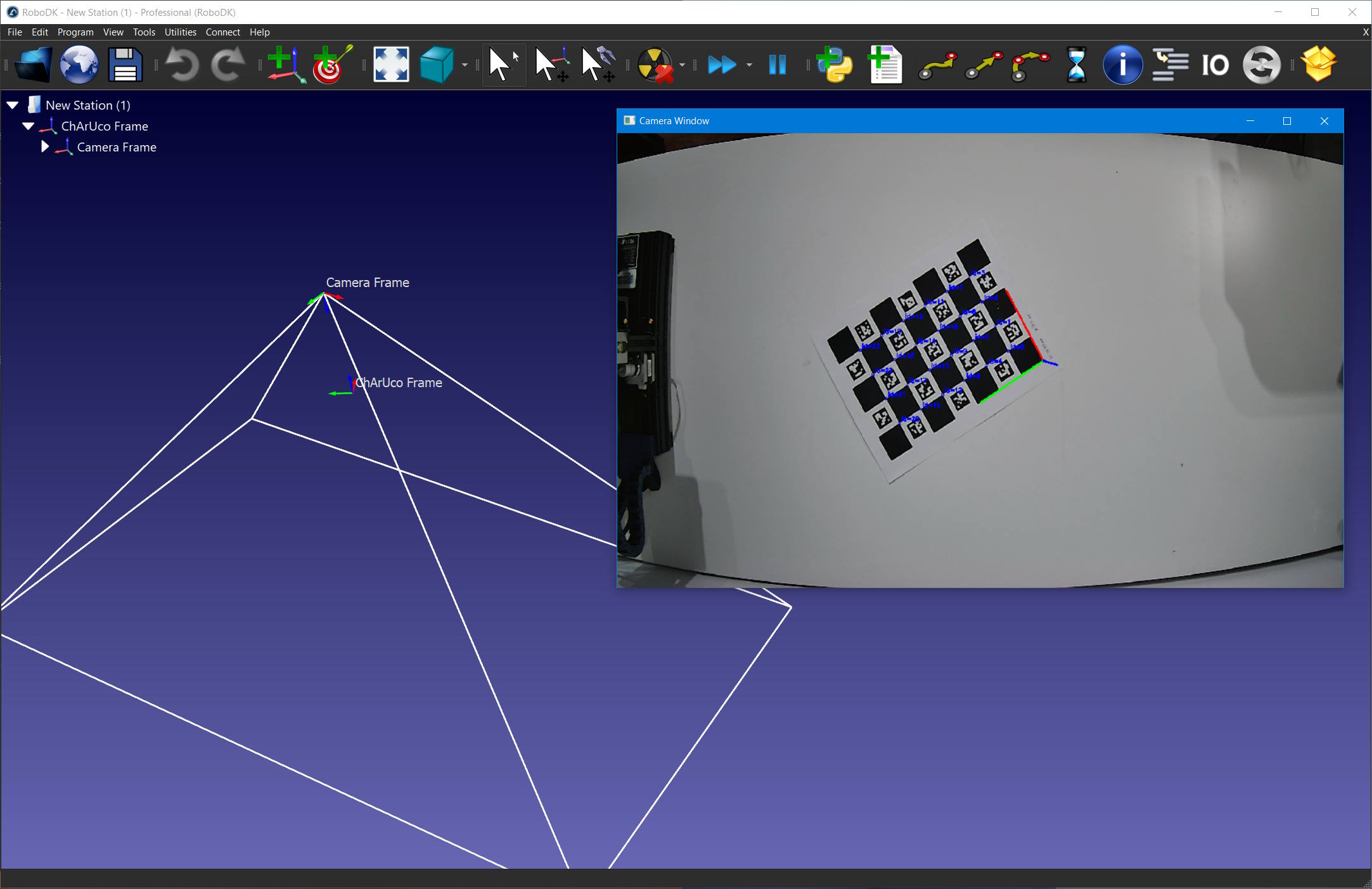
Print the charucoboard in letter format and place it in front of the camera.
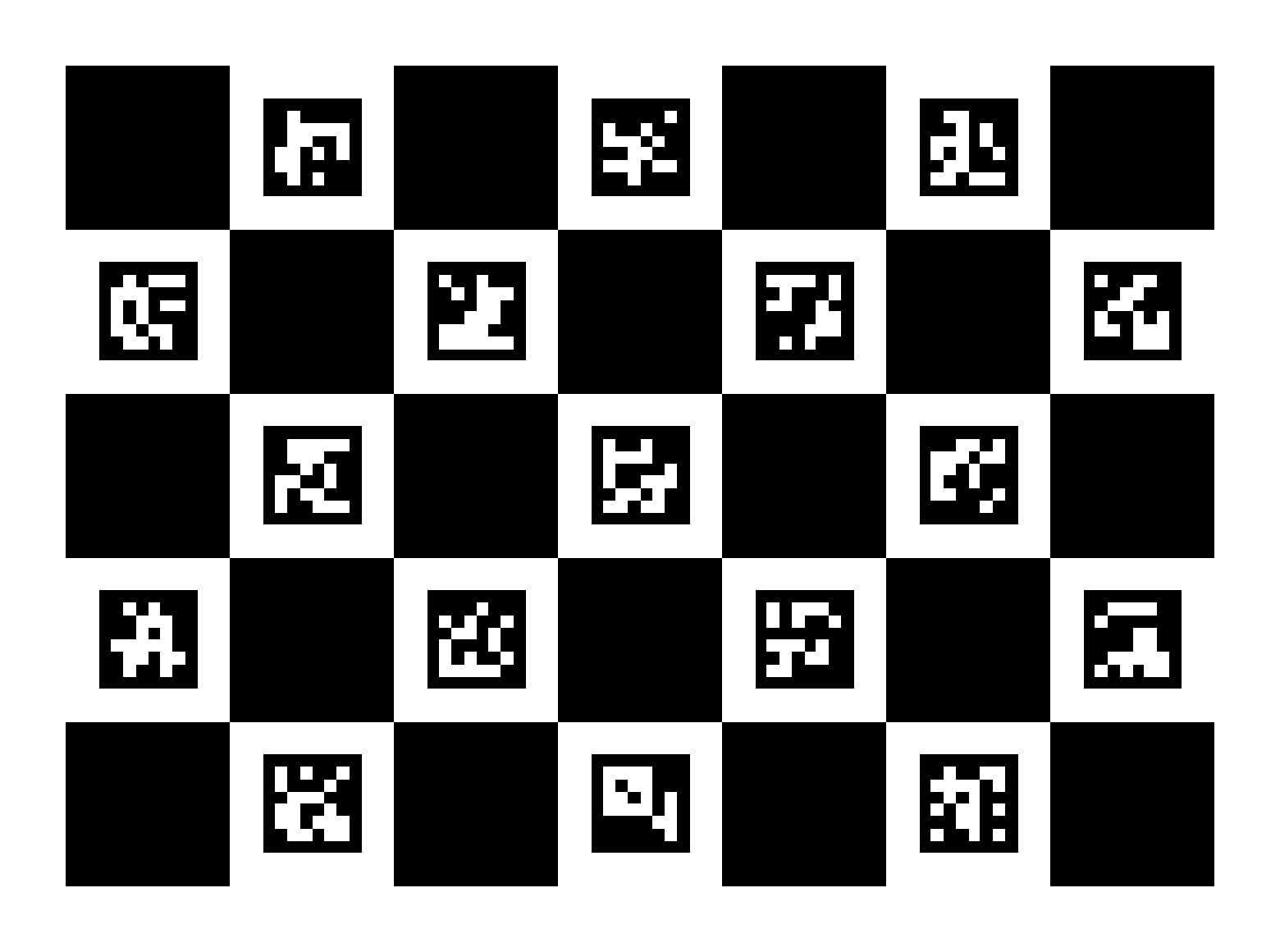
# Type help("robolink") or help("robodk") for more information
# Press F5 to run the script
# Documentation: https://robodk.com/doc/en/RoboDK-API.html
# Reference:     https://robodk.com/doc/en/PythonAPI/index.html
#
# Estimate a camera pose using OpenCV and a ChArUco board.
# More details on ChArUco board: https://docs.opencv.org/master/df/d4a/tutorial_charuco_detection.html
# You can print this board in letter format: https://docs.opencv.org/master/charucoboard.jpg
# Camera calibration is required for pose estimation, see https://robodk.com/doc/en/PythonAPI/examples.html#camera-calibration

from robodk.robolink import *
from robodk.robomath import *
from robodk.robodialogs import *
import cv2 as cv
import numpy as np

#----------------------------------------------
# If you have more than one device, change this accordingly
DEVICE_ID = 0

# You can edit these settings for your board
SQUARES_X = 5  # number of squares along the X axis
SQUARES_Y = 7  # number of squares along the Y axis
SQUARE_LENGTH = 35.0  # mm, length of one square
MARKER_LENGTH = 23.0  # mm, length of one marker
DICTIONNARY = cv.aruco.getPredefinedDictionary(cv.aruco.DICT_6X6_250)  # Predefined dictionary of 250 6x6 bits markers
CHARUCOBOARD = cv.aruco.CharucoBoard_create(SQUARES_X, SQUARES_Y, SQUARE_LENGTH, MARKER_LENGTH, DICTIONNARY)

# Camera settings
CAMERA_WIDTH = 1920  # px
CAMERA_HEIGHT = 1080  # px
CAMERA_APERTURE = 2.0  # mm

#----------------------------------------------
# Link to RoboDK
RDK = Robolink()

# Get the camera
capture = cv.VideoCapture(DEVICE_ID)
if not capture.isOpened():
    RDK.ShowMessage("Selected device id [{0}] could not be opened. Ensure the camera is plugged in and that no other application is using it.".format(DEVICE_ID))
    quit()

# Set the camera resolution. If the resolution is not found, it will default to the next available resolution.
capture.set(cv.CAP_PROP_FRAME_WIDTH, CAMERA_WIDTH)
capture.set(cv.CAP_PROP_FRAME_HEIGHT, CAMERA_HEIGHT)
width, height = int(capture.get(cv.CAP_PROP_FRAME_WIDTH)), int(capture.get(cv.CAP_PROP_FRAME_HEIGHT))
print('Camera resolution: {0}, {1}'.format(width, height))

#----------------------------------------------
# Get the camera calibration parameters
# See https://robodk.com/doc/en/PythonAPI/examples.html#camera-calibration
file = getOpenFileName(strfile='RoboDK-Camera-Settings.yaml', strtitle='Open calibration settings file..', defaultextension='.yaml', filetypes=[('YAML files', '.yaml')])
cv_file = cv.FileStorage(file, cv.FILE_STORAGE_READ)
if not cv_file.isOpened():
    RDK.ShowMessage("Failed to process calibration file")
    quit()
CAMERA_MTX = cv_file.getNode("camera_matrix").mat()
DIST_COEFFS = cv_file.getNode("dist_coeff").mat()
CALIB_SIZE = cv_file.getNode("camera_size").mat().astype(int)
cv_file.release()

# If the calibrated camera resolution and the current resolution differs, approximate the camera matrix
c_width, c_height = CALIB_SIZE
if (width, height) != (c_width, c_height):
    RDK.ShowMessage("The calibrated resolution and the current resolution differs. Approximated calibration matrix will be used.")
    w_ratio = (width / c_width)  # (dimx' / dimx)
    h_ratio = (height / c_height)  # (dimy' / dimy)
    CAMERA_MTX[0][0] = w_ratio * CAMERA_MTX[0][0]  # fx' = (dimx' / dimx) * fx
    CAMERA_MTX[1][1] = h_ratio * CAMERA_MTX[1][1]  # fy' = (dimy' / dimy) * fy
    CAMERA_MTX[0][2] = w_ratio * CAMERA_MTX[0][2]  # cx' = (dimx' / dimx) * cx
    CAMERA_MTX[1][2] = h_ratio * CAMERA_MTX[1][2]  # cy' = (dimy' / dimy) * cy

# Assuming an aperture of 2 mm, update if needed
fovx, fovy, focal_length, p_point, ratio = cv.calibrationMatrixValues(CAMERA_MTX, (width, height), CAMERA_APERTURE, CAMERA_APERTURE)

#----------------------------------------------
# Close camera windows, if any
RDK.Cam2D_Close(0)

# Create the charuco frame for the pose estimation
board_frame_name = 'ChArUco Frame'
board_ref = RDK.Item(board_frame_name, ITEM_TYPE_FRAME)
if not board_ref.Valid():
    board_ref = RDK.AddFrame(board_frame_name)

# Create a frame on which to attach the camera
cam_frame_name = 'Camera Frame'
cam_ref = RDK.Item(cam_frame_name, ITEM_TYPE_FRAME)
if not cam_ref.Valid():
    cam_ref = RDK.AddFrame(cam_frame_name)
cam_ref.setParent(board_ref)

# Simulated camera
cam_name = 'Camera'
cam_id = RDK.Item(cam_name, ITEM_TYPE_CAMERA)
if cam_id.Valid():
    cam_id.Delete()  # Reusing the same camera doesn't apply the settings correctly
camera_settings = 'FOCAL_LENGTH={0:0.0f} FOV={1:0.0f} SNAPSHOT={2:0.0f}x{3:0.0f} SIZE={2:0.0f}x{3:0.0f}'.format(focal_length, fovy, width, height)
cam_id = RDK.Cam2D_Add(cam_ref, camera_settings)
cam_id.setName(cam_name)
cam_id.setParent(cam_ref)

# Create an output window
preview_window = 'Camera Window'
cv.namedWindow(preview_window, cv.WINDOW_KEEPRATIO)
cv.resizeWindow(preview_window, width, height)

#----------------------------------------------
# Find the camera pose
while capture.isOpened():

    # Get the image from the camera
    success, image = capture.read()
    if not success or image is None:
        continue

    # Find the board markers
    mcorners, mids, _ = cv.aruco.detectMarkers(image, DICTIONNARY, None, None, None, None, CAMERA_MTX, DIST_COEFFS)
    if mids is not None and len(mids) > 0:

        # Interpolate the charuco corners from the markers
        count, corners, ids = cv.aruco.interpolateCornersCharuco(mcorners, mids, image, CHARUCOBOARD, None, None, CAMERA_MTX, DIST_COEFFS, 2)
        if count > 0 and len(ids) > 0:
            print('Detected Corners: %i, Ids: %i' % (len(corners), len(ids)))

            # Draw corners on the image
            cv.aruco.drawDetectedCornersCharuco(image, corners, ids)

            # Estimate the charuco board pose
            success, rvec, tvec = cv.aruco.estimatePoseCharucoBoard(corners, ids, CHARUCOBOARD, CAMERA_MTX, DIST_COEFFS, None, None, False)
            if success:
                # Draw axis on image
                image = cv.aruco.drawAxis(image, CAMERA_MTX, DIST_COEFFS, rvec, tvec, 100.)

                # You can filter how much marker needs to be found in order to update the pose as follow
                board_size = CHARUCOBOARD.getChessboardSize()
                min_corners = int((board_size[0] - 1) * (board_size[1] - 1) * 0.5)  # as a % of the total
                if corners.shape[0] >= min_corners and ids.size >= min_corners:

                    # Find the camera pose
                    rmat = cv.Rodrigues(rvec)[0]
                    camera_position = -np.matrix(rmat).T * np.matrix(tvec)
                    cam_xyz = camera_position.T.tolist()[0]
                    vx, vy, vz = rmat.tolist()

                    # Build the camera pose for RoboDK
                    pose = eye(4)
                    pose.setPos(cam_xyz)
                    pose.setVX(vx)
                    pose.setVY(vy)
                    pose.setVZ(vz)

                    # Update the pose in RoboDK
                    cam_ref.setPose(pose)

    #----------------------------------------------
    # Display the charuco board
    cv.imshow(preview_window, image)
    key = cv.waitKey(1)
    if key == 27:
        break  # User pressed ESC, exit
    if cv.getWindowProperty(preview_window, cv.WND_PROP_VISIBLE) < 1:
        break  # User killed the main window, exit

# Release the device
capture.release()
cv.destroyAllWindows()
6.32.5. Camera FoV
This example shows how to automatically create an object representing the camera Field of Vision (FoV) and verify if an object is contained within that FoV. To create the FoV object automatically, a camera object needs to be included in the station.
# Type help("robolink") or help("robodk") for more information
# Press F5 to run the script
# Documentation: https://robodk.com/doc/en/RoboDK-API.html
# Reference:     https://robodk.com/doc/en/PythonAPI/index.html
#
# This example shows how to create a RoboDK Shape to represent a camera's FoV
# and verify if an object is within that shape.
from robodk.robolink import Robolink, ITEM_TYPE_CAMERA, ITEM_TYPE_OBJECT
from robodk import robomath

#----------------------------------
# You might need to play arround these settings depending on the object/setup
CAMERA_NAME = 'RGB-D Camera'
ANIMATE_OBJECT = True

#----------------------------------
# Get the simulated camera from RoboDK
RDK = Robolink()

cam_item = RDK.Item(CAMERA_NAME, ITEM_TYPE_CAMERA)
if not cam_item.Valid():
    cam_item = RDK.Cam2D_Add(RDK.ActiveStation())  # Do not set the DEPTH option here, as we are retrieving both RGB and DEPTH images
    cam_item.setName(CAMERA_NAME)
cam_item.setParam('Open', 1)


#----------------------------------
# Retrieve camera settings / camera matrix
def settings_to_dict(settings):
    if not settings:
        return {}

    settings_dict = {}
    settings_list = [setting.split('=') for setting in settings.strip().split(' ')]
    for setting in settings_list:
        key = setting[0].upper()
        val = setting[-1]

        if key in ['FOV', 'PIXELSIZE', 'FOCAL_LENGTH', 'FAR_LENGTH']:
            val = float(val)
        elif key in ['SIZE', 'ACTUALSIZE', 'SNAPSHOT']:
            w, h = val.split('x')
            val = (int(w), int(h))
        elif key == val.upper():
            val = True  # Flag

        settings_dict[key] = val

    return settings_dict


cam_settings = settings_to_dict(cam_item.setParam('Settings'))

# Retrieve cam settings to be used in FoV Shape Creation
w, h = cam_settings['SIZE']
focal_length = cam_settings['FOCAL_LENGTH']
pixel_size = cam_settings['PIXELSIZE']
camera_range = cam_settings['FAR_LENGTH']

# Creates cam FoV Shape using cam settings
HFOV = 2 * robomath.atan2((w * pixel_size / 1000.0), (2 * focal_length))
VFOV = 2 * robomath.atan2((h * pixel_size / 1000.0), (2 * focal_length))
fov_items = []
fov_items.append(RDK.AddShape([[0, 0, 0], [camera_range * robomath.tan(HFOV / 2), camera_range * robomath.tan(VFOV / 2), camera_range], [-camera_range * robomath.tan(HFOV / 2), camera_range * robomath.tan(VFOV / 2), camera_range]]))
fov_items.append(RDK.AddShape([[0, 0, 0], [-camera_range * robomath.tan(HFOV / 2), camera_range * robomath.tan(VFOV / 2), camera_range], [-camera_range * robomath.tan(HFOV / 2), -camera_range * robomath.tan(VFOV / 2), camera_range]]))
fov_items.append(RDK.AddShape([[0, 0, 0], [camera_range * robomath.tan(HFOV / 2), -camera_range * robomath.tan(VFOV / 2), camera_range], [camera_range * robomath.tan(HFOV / 2), camera_range * robomath.tan(VFOV / 2), camera_range]]))
fov_items.append(RDK.AddShape([[0, 0, 0], [-camera_range * robomath.tan(HFOV / 2), -camera_range * robomath.tan(VFOV / 2), camera_range], [camera_range * robomath.tan(HFOV / 2), -camera_range * robomath.tan(VFOV / 2), camera_range]]))
fov_items.append(RDK.AddShape([[-camera_range * robomath.tan(HFOV / 2), -camera_range * robomath.tan(VFOV / 2), camera_range], [camera_range * robomath.tan(HFOV / 2), -camera_range * robomath.tan(VFOV / 2), camera_range], [-camera_range * robomath.tan(HFOV / 2), camera_range * robomath.tan(VFOV / 2), camera_range]]))
fov_items.append(RDK.AddShape([[camera_range * robomath.tan(HFOV / 2), camera_range * robomath.tan(VFOV / 2), camera_range], [camera_range * robomath.tan(HFOV / 2), -camera_range * robomath.tan(VFOV / 2), camera_range], [-camera_range * robomath.tan(HFOV / 2), camera_range * robomath.tan(VFOV / 2), camera_range]]))

# Merges all created items into 1 shape
fov = RDK.MergeItems(fov_items)
fov.setName("Camera FoV")
fov.setParent(cam_item)
fov.setVisible(False)

# Select an existing object and verifies if the object is seen by the camera
obj_item = RDK.ItemUserPick(itemtype_or_list=ITEM_TYPE_OBJECT)
if not obj_item.Valid():
    obj_item = None

if obj_item is not None:
    obj_item.IsInside(fov)
6.32.6. Augmented Reality
This example shows how to apply augmented reality from RoboDK to on a input camera feed using OpenCV. You need a calibrated camera to estimate the camera pose, see the previous example.
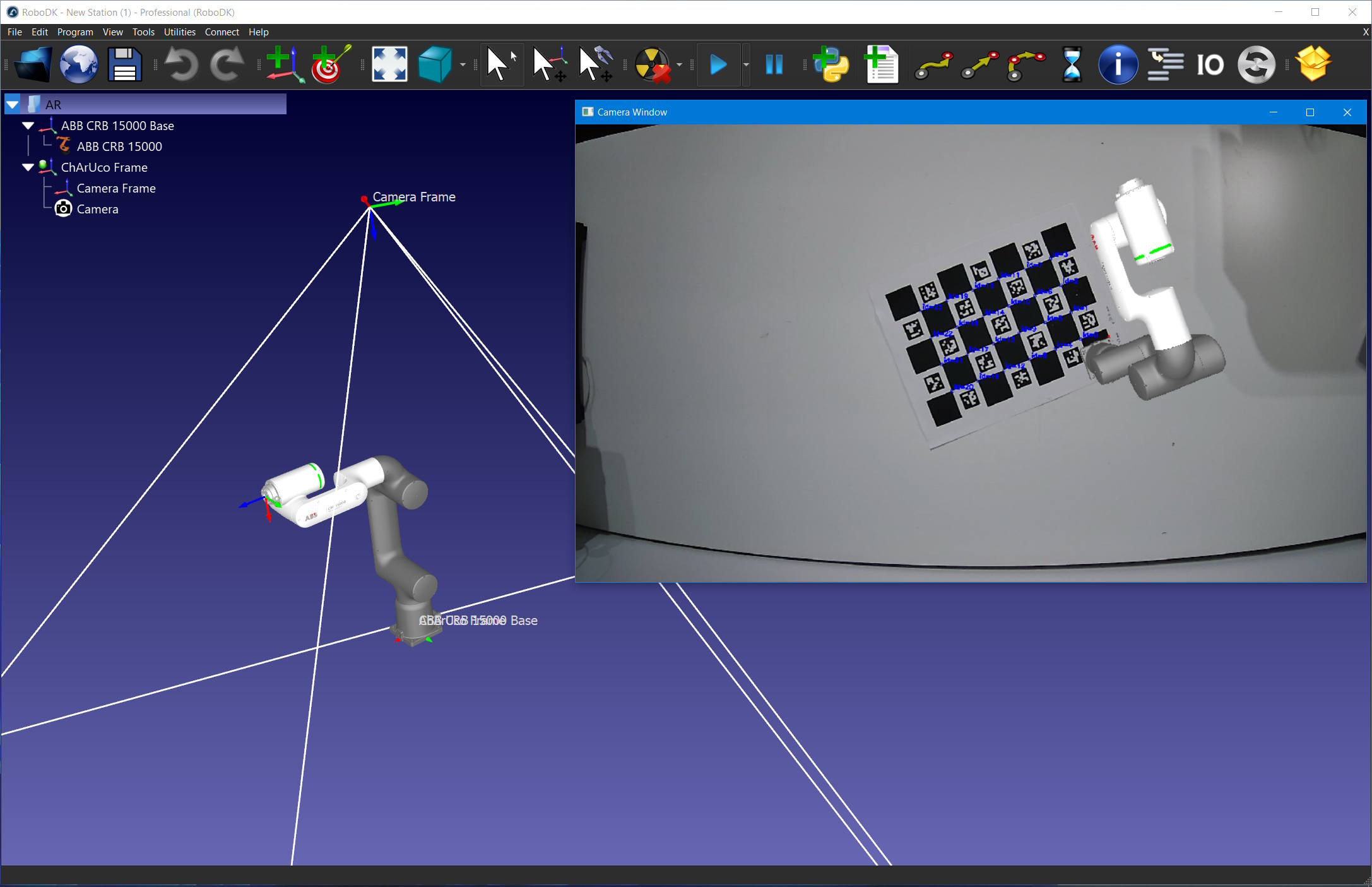
# Type help("robolink") or help("robodk") for more information
# Press F5 to run the script
# Documentation: https://robodk.com/doc/en/RoboDK-API.html
# Reference:     https://robodk.com/doc/en/PythonAPI/index.html
#
# Apply augmented reality using OpenCV and a ChArUco board.
# More details on ChArUco board: https://docs.opencv.org/master/df/d4a/tutorial_charuco_detection.html
# You can print this board in letter format: https://docs.opencv.org/master/charucoboard.jpg
# Camera calibration is required for pose estimation, see https://robodk.com/doc/en/PythonAPI/examples.html#camera-calibration

from robodk.robolink import *
from robodk.robomath import *
from robodk.robodialogs import *
import cv2 as cv
import numpy as np

#----------------------------------------------
# If you have more than one device, change this accordingly
DEVICE_ID = 0

# You can edit these settings for your board
SQUARES_X = 5  # number of squares along the X axis
SQUARES_Y = 7  # number of squares along the Y axis
SQUARE_LENGTH = 35.0  # mm, length of one square
MARKER_LENGTH = 23.0  # mm, length of one marker

SCALE = 1  # You might want to edit this if you do not wish to have a 1:1 scale.

DICTIONNARY = cv.aruco.getPredefinedDictionary(cv.aruco.DICT_6X6_250)  # Predefined dictionary of 250 6x6 bits markers
CHARUCOBOARD = cv.aruco.CharucoBoard_create(SQUARES_X, SQUARES_Y, SQUARE_LENGTH / SCALE, MARKER_LENGTH / SCALE, DICTIONNARY)

# Camera settings
CAMERA_WIDTH = 1920  # px
CAMERA_HEIGHT = 1080  # px
CAMERA_APERTURE = 2.0  # mm


#----------------------------------------------
# Utility function to merge the RoboDK image with the input image
def merge_img(img_bg, img_fg):

    # Mask and inverse-mask of AR image
    _, mask = cv.threshold(cv.cvtColor(img_fg, cv.COLOR_BGR2GRAY), 10, 255, cv.THRESH_BINARY)
    mask_inv = cv.bitwise_not(mask)

    # Black-out AR area from environnement image
    img1_bg = cv.bitwise_and(img_bg, img_bg, mask=mask_inv)

    # Take-out AR area from AR image
    img2_fg = cv.bitwise_and(img_fg, img_fg, mask=mask)

    # Merge
    return cv.add(img1_bg, img2_fg)


#----------------------------------------------
# Link to RoboDK
RDK = Robolink()

# Get the camera
capture = cv.VideoCapture(DEVICE_ID)
if not capture.isOpened():
    RDK.ShowMessage("Selected device id [{0}] could not be opened. Ensure the camera is plugged in and that no other application is using it.".format(DEVICE_ID))
    quit()

# Set the camera resolution. If the resolution is not found, it will default to the next available resolution.
capture.set(cv.CAP_PROP_FRAME_WIDTH, CAMERA_WIDTH)
capture.set(cv.CAP_PROP_FRAME_HEIGHT, CAMERA_HEIGHT)
width, height = int(capture.get(cv.CAP_PROP_FRAME_WIDTH)), int(capture.get(cv.CAP_PROP_FRAME_HEIGHT))
print('Camera resolution: {0}, {1}'.format(width, height))

#----------------------------------------------
# Get the camera calibration parameters
file = getOpenFileName(strfile='RoboDK-Camera-Settings.yaml', strtitle='Open calibration settings file..', defaultextension='.yaml', filetypes=[('YAML files', '.yaml')])
cv_file = cv.FileStorage(file, cv.FILE_STORAGE_READ)
if not cv_file.isOpened():
    RDK.ShowMessage("Failed to process calibration file")
    quit()
CAMERA_MTX = cv_file.getNode("camera_matrix").mat()
DIST_COEFFS = cv_file.getNode("dist_coeff").mat()
CALIB_SIZE = cv_file.getNode("camera_size").mat().astype(int)
cv_file.release()

# If the calibrated camera resolution and the current resolution differs, approximate the camera matrix
c_width, c_height = CALIB_SIZE
if (width, height) != (c_width, c_height):
    RDK.ShowMessage("The calibrated resolution and the current resolution differs. Approximated calibration matrix will be used.")
    CAMERA_MTX[0][0] = (width / c_width) * CAMERA_MTX[0][0]  # fx' = (dimx' / dimx) * fx
    CAMERA_MTX[1][1] = (height / c_height) * CAMERA_MTX[1][1]  # fy' = (dimy' / dimy) * fy

# Assuming an aperture of 2 mm, update if needed
fovx, fovy, focal_length, p_point, ratio = cv.calibrationMatrixValues(CAMERA_MTX, (width, height), CAMERA_APERTURE, CAMERA_APERTURE)

#----------------------------------------------
# Close camera windows, if any
RDK.Cam2D_Close(0)

# Create the charuco frame for the pose estimation
board_frame_name = 'ChArUco Frame'
board_ref = RDK.Item(board_frame_name, ITEM_TYPE_FRAME)
if not board_ref.Valid():
    board_ref = RDK.AddFrame(board_frame_name)

# Create a frame on which to attach the camera
cam_frame_name = 'Camera Frame'
cam_ref = RDK.Item(cam_frame_name, ITEM_TYPE_FRAME)
if not cam_ref.Valid():
    cam_ref = RDK.AddFrame(cam_frame_name)
cam_ref.setParent(board_ref)

# Simulated camera
cam_name = 'Camera'
cam_id = RDK.Item(cam_name, ITEM_TYPE_CAMERA)
if cam_id.Valid():
    cam_id.Delete()  # Reusing the same camera doesn't apply the settings correctly
camera_settings = 'FOCAL_LENGTH={0:0.0f} FOV={1:0.0f} BG_COLOR=black FAR_LENGTH=5000 SNAPSHOT={2:0.0f}x{3:0.0f} SIZE={2:0.0f}x{3:0.0f}'.format(focal_length, fovy, width, height)
cam_id = RDK.Cam2D_Add(cam_ref, camera_settings)
cam_id.setName(cam_name)
cam_id.setParent(cam_ref.Parent())

# Create an output window
preview_window = 'Camera Window'
cv.namedWindow(preview_window, cv.WINDOW_KEEPRATIO)
cv.resizeWindow(preview_window, width, height)

#----------------------------------------------
# Find the camera pose
while capture.isOpened():

    # Get the image from the camera
    success, image = capture.read()
    if not success or image is None:
        continue

    # Find the board markers
    mcorners, mids, _ = cv.aruco.detectMarkers(image, DICTIONNARY, None, None, None, None, CAMERA_MTX, DIST_COEFFS)
    if mids is not None and len(mids) > 0:

        # Interpolate the charuco corners from the markers
        count, corners, ids = cv.aruco.interpolateCornersCharuco(mcorners, mids, image, CHARUCOBOARD, None, None, CAMERA_MTX, DIST_COEFFS, 2)
        if count > 0 and len(ids) > 0:
            print('Detected Corners: %i, Ids: %i' % (len(corners), len(ids)))

            # Draw corners on the image
            cv.aruco.drawDetectedCornersCharuco(image, corners, ids)

            # Estimate the charuco board pose
            success, rvec, tvec = cv.aruco.estimatePoseCharucoBoard(corners, ids, CHARUCOBOARD, CAMERA_MTX, DIST_COEFFS, None, None, False)
            if success:
                # Draw axis on image
                image = cv.aruco.drawAxis(image, CAMERA_MTX, DIST_COEFFS, rvec, tvec, 100.)

                # You can filter how much marker needs to be found in order to update the pose as follow
                board_size = CHARUCOBOARD.getChessboardSize()
                min_corners = int((board_size[0] - 1) * (board_size[1] - 1) * 0.8)  # as a % of the total
                if corners.shape[0] >= min_corners and ids.size >= min_corners:

                    # Find the camera pose
                    rmat = cv.Rodrigues(rvec)[0]
                    camera_position = -np.matrix(rmat).T * np.matrix(tvec)
                    cam_xyz = camera_position.T.tolist()[0]
                    vx, vy, vz = rmat.tolist()

                    # Build the camera pose for RoboDK
                    pose = eye(4)
                    pose.setPos(cam_xyz)
                    pose.setVX(vx)
                    pose.setVY(vy)
                    pose.setVZ(vz)

                    # Update the pose in RoboDK
                    cam_ref.setPose(pose)

    #----------------------------------------------
    # Get the RDK camera image
    image_rdk = None
    bytes_img = RDK.Cam2D_Snapshot("", cam_id)
    nparr = np.frombuffer(bytes_img, np.uint8)
    image_rdk = cv.imdecode(nparr, cv.IMREAD_COLOR)

    # Apply AR
    image = merge_img(image, image_rdk)

    #----------------------------------------------
    # Display the charuco board
    cv.imshow(preview_window, image)
    key = cv.waitKey(1)
    if key == 27:
        break  # User pressed ESC, exit
    if cv.getWindowProperty(preview_window, cv.WND_PROP_VISIBLE) < 1:
        break  # User killed the main window, exit

# Release the device
capture.release()
cv.destroyAllWindows()
6.32.7. QR codes and barcodes
This example shows how to read QR codes and barcodes (EAN-13, UPC-A, etc) from an input camera in RoboDK. The input camera can be a physical device or a simulated camera from RoboDK. It also provides utility scripts to add QR codes and barcodes as objects to a RoboDK station.
Detected QR code and barcodes will be shown in a separate view window, with detection highlighted in red. After detection, you can request the robot to place the item on a specific conveyor, bin, etc. based on the readings.
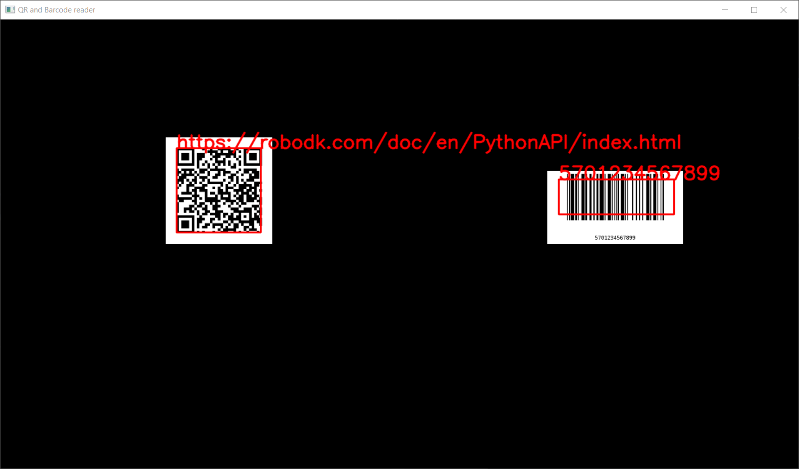
6.32.7.1. Generating QR codes
# Type help("robolink") or help("robodk") for more information
# Press F5 to run the script
# Documentation: https://robodk.com/doc/en/RoboDK-API.html
# Reference:     https://robodk.com/doc/en/PythonAPI/index.html
#
# This script allows you to create a RoboDK object containing a QR code.

from robodk.robolink import *  # RoboDK API
from robodk.robodialogs import *

import_install("qrcode")
import qrcode

#----------------------------------------------
# Settings
ASK_USER_SAVE_TO_DISK = False  # True to ask the user to save on disk. Otherwise, uses temp folder and add to RoboDK.

#----------------------------------------------
# Create the QR code
data = mbox("Enter the text to embed in your QR code", entry="robodk.com")
if data is None or data is False or type(data) is not str:
    # User cancelled
    quit()
img = qrcode.make(data)

#----------------------------------------------
# Save to file
name = "QR_" + data.replace('.', '').replace(':', '').replace('/', '')  # https://robodk.com/doc/en/PythonAPI/index.html

filename = None
if ASK_USER_SAVE_TO_DISK:
    filename = getSaveFileName(strtitle='Save QR on disk, or cancel to skip', strfile=name, defaultextension='.png', filetypes=[('PNG files', '*.png')])
if filename is None or filename == '':
    import tempfile
    import os
    tempdir = tempfile.gettempdir()
    filename = os.path.join(tempdir, name + ".png")

img.save(filename)

import os
if not os.path.exists(filename):
    quit(-1)

#----------------------------------------------
# Import in RoboDK
RDK = Robolink()
img_item = RDK.AddFile(filename)
if not img_item.Valid():
    quit(-1)
6.32.7.2. Generating barcodes (EAN-13)
# Type help("robolink") or help("robodk") for more information
# Press F5 to run the script
# Documentation: https://robodk.com/doc/en/RoboDK-API.html
# Reference:     https://robodk.com/doc/en/PythonAPI/index.html
#
# This script allows you to create a RoboDK object containing a EAN13 bar code (European).

from robodk.robolink import *  # RoboDK API
from robodk.robodialogs import *

import_install("barcode", "python-barcode")
import barcode

#----------------------------------------------
# Settings
ASK_USER_SAVE_TO_DISK = False  # True to ask the user to save on disk. Otherwise, uses temp folder and add to RoboDK.

#----------------------------------------------
# Create the bar code
data = mbox("Enter your bar code (EAN 13 digits)", entry='5701234567899')
if data is None or data is False or type(data) is not str:
    # User cancelled
    quit()
if not data.isdecimal() or len(data) != 13:
    # Invalid input
    quit()
img = barcode.EAN13(data, writer=barcode.writer.ImageWriter())

# You can easily copy this script to generate other bar codes type, such as UPC-A
#img = barcode.UPCA(data, writer=barcode.writer.ImageWriter())

#----------------------------------------------
# Save to file
name = "EAN13_" + data.replace('.', '').replace(':', '').replace('/', '')

filename = None
if ASK_USER_SAVE_TO_DISK:
    filename = getSaveFileName(strtitle='Save bar code on disk, or cancel to skip', strfile=name, defaultextension='.png', filetypes=[('PNG files', '*.png')])
if filename is None or filename == '':
    import tempfile
    import os
    tempdir = tempfile.gettempdir()
    filename = os.path.join(tempdir, name)

img.save(filename)

filename += '.png'  # barcode .save adds the .png
import os
if not os.path.exists(filename):
    quit(-1)

#----------------------------------------------
# Import in RoboDK
RDK = Robolink()
img_item = RDK.AddFile(filename)
if not img_item.Valid():
    quit(-1)
6.32.7.3. Reading QR codes and bar codes
# Type help("robolink") or help("robodk") for more information
# Press F5 to run the script
# Documentation: https://robodk.com/doc/en/RoboDK-API.html
# Reference:     https://robodk.com/doc/en/PythonAPI/index.html
#
# This script process a camera frame to extract QR and bar codes.
# It currently uses a RoboDK camera, but it can be easily adapted to use a physical device.

from robodk.robolink import *  # RoboDK API
from robodk.robomath import *  # Robot toolbox

import_install("cv2", "opencv-contrib-python")  # The contrib version adds the barcode support
import cv2 as cv
import tempfile

#----------------------------------------------
# Settings
PROCESS_COUNT = -1  # How many frames to process before exiting. -1 means indefinitely.
DETECT_COLOR = (0, 0, 255)

#----------------------------------------------
# Start a camera feed.
# If you are using a connected device, use cv.VideoCapture to get the livefeed.
# https://docs.opencv.org/master/d8/dfe/classcv_1_1VideoCapture.html
#
# capture = cv.VideoCapture(0)
# retval, image = capture.read()

#----------------------------------------------
# Get the camera from RoboDK
RDK = Robolink()
cam_item = RDK.ItemUserPick("Select the camera", ITEM_TYPE_CAMERA)
if not cam_item.Valid():
    quit()

#----------------------------------------------
# Initialize the QR and barcode detectors
qr_detector = cv.QRCodeDetector()  # https://docs.opencv.org/master/de/dc3/classcv_1_1QRCodeDetector.html
barcode_detector = cv.barcode_BarcodeDetector()  # https://docs.opencv.org/master/d2/dea/group__barcode.html

#----------------------------------------------
# For now, we need to save RDK snapshots on disk.
# A new update is coming which will return the image, like: img = RDK.Cam2D_Snapshot('', cam_item)
tempdir = tempfile.gettempdir()
snapshot_file = tempdir + "\\code_reader_temp.png"

#----------------------------------------------
# Process camera frames
count = 0
while count < PROCESS_COUNT or PROCESS_COUNT < 0:
    count += 1

    #----------------------------------------------
    # Save and get the image from RoboDK
    if RDK.Cam2D_Snapshot(snapshot_file, cam_item):
        img = cv.imread(snapshot_file)

        #----------------------------------------------
        # Check for QR codes
        retval, decoded_info_list, points_list, straight_qrcode_list = qr_detector.detectAndDecodeMulti(img)
        if retval:
            points_list = points_list.astype(int)
            n_qr = len(decoded_info_list)
            for i in range(n_qr):
                print("Found QR code: " + decoded_info_list[i])

                # Draw the contour
                points = points_list[i]
                n_lines = len(points)
                for j in range(n_lines):
                    point1 = points[j]
                    point2 = points[(j + 1) % n_lines]
                    cv.line(img, point1, point2, color=DETECT_COLOR, thickness=2)

                # Print the QR content
                cv.putText(img, decoded_info_list[i], points[0], cv.FONT_HERSHEY_SIMPLEX, 1, DETECT_COLOR, 2, cv.LINE_AA)

        #----------------------------------------------
        # Check for bar codes
        retval, decoded_info_list, decoded_type_list, points_list = barcode_detector.detectAndDecode(img)
        if retval:
            points_list = points_list.astype(int)
            n_bar = len(decoded_info_list)
            for i in range(n_bar):

                def barcodeType(decoded_type: int):
                    if decoded_type == cv.barcode.EAN_8:
                        return "EAN8"
                    elif decoded_type == cv.barcode.EAN_13:
                        return "EAN13"
                    elif decoded_type == cv.barcode.UPC_A:
                        return "UPC-A"
                    elif decoded_type == cv.barcode.UPC_E:
                        return "UPC-E"
                    elif decoded_type == cv.barcode.UPC_EAN_EXTENSION:
                        return "UPC-EAN"
                    else:
                        return "None"

                barcode_type = barcodeType(decoded_type_list[i])
                print("Found Bar code: " + decoded_info_list[i] + ", [%s]" % barcode_type)

                # Draw the contour
                points = points_list[i]
                n_lines = len(points)
                for j in range(n_lines):
                    point1 = points[j]
                    point2 = points[(j + 1) % n_lines]
                    cv.line(img, point1, point2, color=DETECT_COLOR, thickness=2)

                # Print the barcode content
                cv.putText(img, decoded_info_list[i], points[1], cv.FONT_HERSHEY_SIMPLEX, 1, DETECT_COLOR, 2, cv.LINE_AA)

        #----------------------------------------------
        # Display on screen
        cv.imshow("QR and Barcode reader", img)
        cv.waitKey(1)

        #----------------------------------------------
        # At this point, you can process the items.
        # For instance, request the robot to place the item on a specific conveyor, bin, etc.
        pause(1)

cv.destroyAllWindows()
6.32.8. Object detection
6.32.8.1. 2D pose estimation of a known object
This example shows how to match an input image (source object) with a camera feed to determine it’s 2D pose using OpenCV. It uses a simulated camera, but it can easily be modified to use an input camera. This only calculates the rotation along the Z axis, and the X/Y offsets. It is not meant for 3D positioning. You can find more information in the OpenCV homography tutorial.
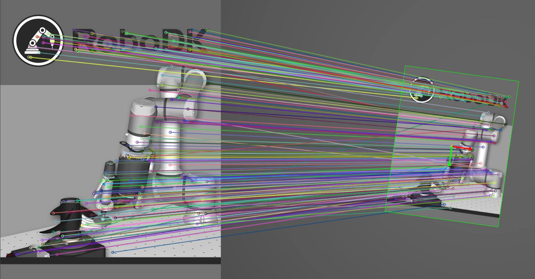
# Type help("robolink") or help("robodk") for more information
# Press F5 to run the script
# Documentation: https://robodk.com/doc/en/RoboDK-API.html
# Reference:     https://robodk.com/doc/en/PythonAPI/index.html
#
# This example shows how to match an input image (source object) with a camera feed to determine it's 2D pose using a SIFT algorithm.
# It uses a simulated camera, but it can easily be modified to use an input camera.
# Warning: This only calculates the rotation along the Z axis, and the X/Y offsets. It is not meant for 3D positioning.
#
# You can find more information in the OpenCV homography tutorials:
# https://docs.opencv.org/master/d7/dff/tutorial_feature_homography.html
# https://docs.opencv.org/master/d9/dab/tutorial_homography.html

from robodk.robolink import *  # RoboDK API
from robodk.robomath import *  # Robot toolbox
from robodk.robodialogs import *

import_install('cv2', 'opencv-contrib-python')
import cv2 as cv
import numpy as np
import tempfile
import math

#----------------------------------
# Settings
PROCESS_COUNT = -1  # How many frames to process before exiting. -1 means indefinitely.

# Camera
CAM_NAME = "Camera"
CAMERA_SIZE_X = 1280.0  # pixel
CAMERA_SIZE_Y = 720.0  # pixel
PIXEL_SIZE_X = (100.0 / 175.0)  # mm/pixel, found experimentally
PIXEL_SIZE_Y = (100.0 / 175.0)  # mm/pixel
Z_OFFSET = 715.0  # mm, distance between the camera and the part surface

# Calculated frame and targets
OBJ_NAME = "RoboDK Box"
CALC_FRAME_NAME = "%s Calc Frame" % OBJ_NAME
CALC_TARGET_NAME = "%s Pick" % OBJ_NAME
CALC_TARGET_APPROACH_NAME = "%s Approach" % CALC_TARGET_NAME
APPROACH_DIST = 100  # mm

# Detection
MATCH_DIST_THRESH = 0.75  # Lowe's ratio threshold
MIN_MATCH = 15  # Minimum SIFT matches to consider the detection valid
OBJ_IMG_PATH = ""  # Absolute path to your source image. Leave empty to open a file dialog.

# Draw results
DISPLAY_RESULT = True  # Opens a window with the SIFT matches
DRAW_AXIS_LENGTH = 50  # pixel
DRAW_LINE_WEIGHT = 1  # pixel
DRAW_LINE_COLOR = (0, 255, 0)  # RGB

#----------------------------------
# Get the source image for recognition
img_path = OBJ_IMG_PATH
if img_path == "":
    img_path = getOpenFileName(strtitle='Select source object image', defaultextension='.png', filetypes=[('PNG', '.png'), ('JPEG', '.jpg')])
img_object = cv.imread(img_path, cv.IMREAD_GRAYSCALE)
if img_object is None or np.shape(img_object) == ():
    raise Exception("Unable to retrieve the source image for recognition!")

#----------------------------------
# Get the part to recognize
RDK = Robolink()

part = RDK.Item(OBJ_NAME, ITEM_TYPE_OBJECT)
if not part.Valid():
    raise Exception("Part not found! %s" % OBJ_NAME)
part_frame = part.Parent()
if not part_frame.Valid() or part_frame.Type() != ITEM_TYPE_FRAME:
    raise Exception("Part parent is invalid, make sur it's a frame!")

#----------------------------------
# Get the simulated camera from RoboDK
cam_item = RDK.Item(CAM_NAME, ITEM_TYPE_CAMERA)
if not cam_item.Valid():
    raise Exception("Camera not found! %s" % CAM_NAME)
cam_tool = cam_item.Parent()
if not cam_tool.Valid() or cam_tool.Type() != ITEM_TYPE_TOOL:
    raise Exception("Camera parent is invalid, make sur it's a tool!")

#----------------------------------
# Get or create the calculated object pose frame
calc_frame = RDK.Item(CALC_FRAME_NAME, ITEM_TYPE_FRAME)
if not calc_frame.Valid():
    calc_frame = RDK.AddFrame(CALC_FRAME_NAME, part_frame.Parent())

calc_pick = RDK.Item(CALC_TARGET_NAME, ITEM_TYPE_TARGET)
if not calc_pick.Valid():
    calc_pick = RDK.AddTarget(CALC_TARGET_NAME, calc_frame)

calc_pick_approach = RDK.Item(CALC_TARGET_APPROACH_NAME, ITEM_TYPE_TARGET)
if not calc_pick_approach.Valid():
    calc_pick_approach = RDK.AddTarget(CALC_TARGET_APPROACH_NAME, calc_frame)

#----------------------------------------------
# Start a camera feed.
# If you are using a connected device, use cv.VideoCapture to get the livefeed.
# https://docs.opencv.org/master/d8/dfe/classcv_1_1VideoCapture.html
#
# capture = cv.VideoCapture(0)
# retval, image = capture.read()

#----------------------------------------------
# For now, we need to save RDK snapshots on disk.
# A new update is coming which will return the image, like: img = RDK.Cam2D_Snapshot('', cam_item)
tempdir = tempfile.gettempdir()
snapshot_file = tempdir + "\\sift_temp.png"

#----------------------------------------------
# Process camera frames
count = 0
while count < PROCESS_COUNT or PROCESS_COUNT < 0:
    count += 1

    #----------------------------------------------
    # Save and get the image from RoboDK
    if RDK.Cam2D_Snapshot(snapshot_file, cam_item):
        img_scene = cv.imread(snapshot_file, cv.IMREAD_GRAYSCALE)

        #----------------------------------------------
        # Detect the keypoints using SIFT Detector, compute the descriptors
        detector = cv.SIFT_create()
        keypoints_obj, descriptors_obj = detector.detectAndCompute(img_object, None)
        keypoints_scene, descriptors_scene = detector.detectAndCompute(img_scene, None)
        if descriptors_obj is None or descriptors_scene is None or keypoints_obj == [] or keypoints_scene == []:
            print("Unable to detect keypoints")
            continue

        # Match descriptor vectors
        matcher = cv.DescriptorMatcher_create(cv.DescriptorMatcher_FLANNBASED)
        knn_matches = matcher.knnMatch(descriptors_obj, descriptors_scene, 2)

        # Filter matches using the Lowe's ratio test
        good_matches = []
        for m, n in knn_matches:
            if m.distance < MATCH_DIST_THRESH * n.distance:
                good_matches.append(m)

        # Draw matches
        img_matches = np.empty((max(img_object.shape[0], img_scene.shape[0]), img_object.shape[1] + img_scene.shape[1], 3), dtype=np.uint8)
        cv.drawMatches(img_object, keypoints_obj, img_scene, keypoints_scene, good_matches, img_matches, flags=cv.DrawMatchesFlags_NOT_DRAW_SINGLE_POINTS)

        # Stop processing on low match count
        if len(good_matches) < MIN_MATCH:
            print("No enough matches")
            continue

        #----------------------------------------------
        # Localize the object
        obj = np.empty((len(good_matches), 2), dtype=np.float32)
        scene = np.empty((len(good_matches), 2), dtype=np.float32)
        for i in range(len(good_matches)):
            # Get the keypoints from the good matches
            obj[i, 0] = keypoints_obj[good_matches[i].queryIdx].pt[0]
            obj[i, 1] = keypoints_obj[good_matches[i].queryIdx].pt[1]
            scene[i, 0] = keypoints_scene[good_matches[i].trainIdx].pt[0]
            scene[i, 1] = keypoints_scene[good_matches[i].trainIdx].pt[1]

        # Calculate the perspective transformation, or Homography matrix
        H, _ = cv.findHomography(obj, scene, cv.RANSAC)
        if H is None or np.shape(H) == ():
            print("No transformation possible")
            continue

        # We can extract the rotation angle from H directly
        theta = -math.atan2(H[0, 1], H[0, 0])

        #----------------------------------------------
        # There are many ways to calculate the pose.
        #
        # 1. Using a camera matrix
        #    If you you have a calibrated camera (simulated or hardware), you can decompose H and get the rotation and translation solutions (up to four solutions).
        #    See our examples on how to calibrate a camera:
        #    - https://robodk.com/doc/en/PythonAPI/examples.html#camera-calibration
        #
        # cam_mtx = np.array([[1.3362190822261939e+04, 0., 8.4795067509033629e+02], [0., 1.3361819220999134e+04, 1.6875586379396785e+02], [0., 0., 1.]])  # Sample camera matrix from a 1280x720 simulated camera
        # n_solution, rot, trans, normals = cv.decomposeHomographyMat(H, cam_mtx)
        # for i in range(n_solution):
        #     vx, vy, vz = rot[i].tolist()
        #     tx, ty, tz = trans[i].tolist()

        #----------------------------------------------
        # 2. Using moments
        #    This method does not take into account the camera matrix, small errors are expected.
        #    For more information, visit:
        #    - https://en.wikipedia.org/wiki/Image_moment
        #    - https://docs.opencv.org/master/d8/d23/classcv_1_1Moments.html

        # Get the corners from the object image
        obj_corners = np.zeros((4, 1, 2), dtype=np.float32)  # corder id, x, y
        obj_corners[1, 0, 0] = img_object.shape[1]
        obj_corners[2, 0, 0] = img_object.shape[1]
        obj_corners[2, 0, 1] = img_object.shape[0]
        obj_corners[3, 0, 1] = img_object.shape[0]

        # Transform the object corners to the camera image
        scene_corners = cv.perspectiveTransform(obj_corners, H)

        # Get the image moments, and extract the center
        moments = cv.moments(scene_corners)
        cx = moments['m10'] / moments['m00']
        cy = moments['m01'] / moments['m00']

        #----------------------------------------------
        # Calculate X and Y relative to the camera frame
        rel_x = (cx - CAMERA_SIZE_X / 2.0) * PIXEL_SIZE_X
        rel_y = (cy - CAMERA_SIZE_Y / 2.0) * PIXEL_SIZE_Y
        rel_theta = float(theta)

        # Centered tolerance
        if abs(rel_x) < 1:
            rel_x = 0.0
        if abs(rel_y) < 1:
            rel_y = 0.0
        if abs(rel_theta) < 0.0005:
            rel_theta = 0.0

        # Precision tolerance
        rel_x = round(rel_x, 4)
        rel_y = round(rel_y, 4)
        rel_theta = round(rel_theta, 4)

        # Calculate the pose wrt to the camera
        calc_frame_pose = cam_tool.Pose()
        calc_frame_pose.setPos([rel_x, rel_y, Z_OFFSET])
        calc_frame_pose = calc_frame_pose * rotz(rel_theta)

        # Lazy way of calculating a set of relative poses is to static move them around!
        calc_frame.setParent(cam_tool)
        calc_frame.setPose(calc_frame_pose)
        calc_pick.setPose(eye(4))
        calc_pick_approach.setPose(calc_pick.Pose() * transl(0, 0, -APPROACH_DIST))
        calc_frame.setParentStatic(part_frame)

        #----------------------------------------------
        # Display the detection to the user (reference image and camera image side by side, with detection results)
        if DISPLAY_RESULT:

            def rotate(origin, point, angle):
                """Rotate a point counterclockwise by a given angle (radians) around a given origin."""
                ox, oy = origin
                px, py = point
                qx = ox + math.cos(angle) * (px - ox) - math.sin(angle) * (py - oy)
                qy = oy + math.sin(angle) * (px - ox) + math.cos(angle) * (py - oy)
                return qx, qy

            # Construct the drawing parameters
            cx_off = img_object.shape[1]
            center_pt = (cx + cx_off, cy)
            x_axis = (center_pt[0] + DRAW_AXIS_LENGTH, center_pt[1])
            x_axis = rotate(center_pt, x_axis, theta)
            y_axis = rotate(center_pt, x_axis, pi / 2.0)

            center_pt = (int(center_pt[0]), int(center_pt[1]))
            x_axis = (int(x_axis[0]), int(x_axis[1]))
            y_axis = (int(y_axis[0]), int(y_axis[1]))

            # Draw the orientation vector of the detected object
            cv.circle(img_matches, center_pt, 3, (0, 255, 255), -1)
            cv.arrowedLine(img_matches, center_pt, x_axis, (0, 0, 255), 2, cv.LINE_AA)  # X
            cv.arrowedLine(img_matches, center_pt, y_axis, (0, 255, 0), 2, cv.LINE_AA)  # Y

            # Draw lines between the corners of the detected object
            cv.line(img_matches, (int(scene_corners[0,0,0] + img_object.shape[1]), int(scene_corners[0,0,1])),\
                (int(scene_corners[1,0,0] + img_object.shape[1]), int(scene_corners[1,0,1])), DRAW_LINE_COLOR, DRAW_LINE_WEIGHT)
            cv.line(img_matches, (int(scene_corners[1,0,0] + img_object.shape[1]), int(scene_corners[1,0,1])),\
                (int(scene_corners[2,0,0] + img_object.shape[1]), int(scene_corners[2,0,1])), DRAW_LINE_COLOR, DRAW_LINE_WEIGHT)
            cv.line(img_matches, (int(scene_corners[2,0,0] + img_object.shape[1]), int(scene_corners[2,0,1])),\
                (int(scene_corners[3,0,0] + img_object.shape[1]), int(scene_corners[3,0,1])), DRAW_LINE_COLOR, DRAW_LINE_WEIGHT)
            cv.line(img_matches, (int(scene_corners[3,0,0] + img_object.shape[1]), int(scene_corners[3,0,1])),\
                (int(scene_corners[0,0,0] + img_object.shape[1]), int(scene_corners[0,0,1])), DRAW_LINE_COLOR, DRAW_LINE_WEIGHT)

            # Show detected matches
            wdw_name = 'RoboDK - Matches and detected object'
            cv.imshow(wdw_name, img_matches)
            key = cv.waitKey(1)
            if key == 27:
                break  # User pressed ESC, exit
            if cv.getWindowProperty(wdw_name, cv.WND_PROP_VISIBLE) < 1:
                break  # User killed the main window, exit

cv.destroyAllWindows()
6.32.8.2. Blob detection
This example shows how to detect simple geometrical shapes (blobs) using OpenCV. It uses a simulated camera, but it can easily be modified to use an input camera. You can find more information in the OpenCV contours tutorial.
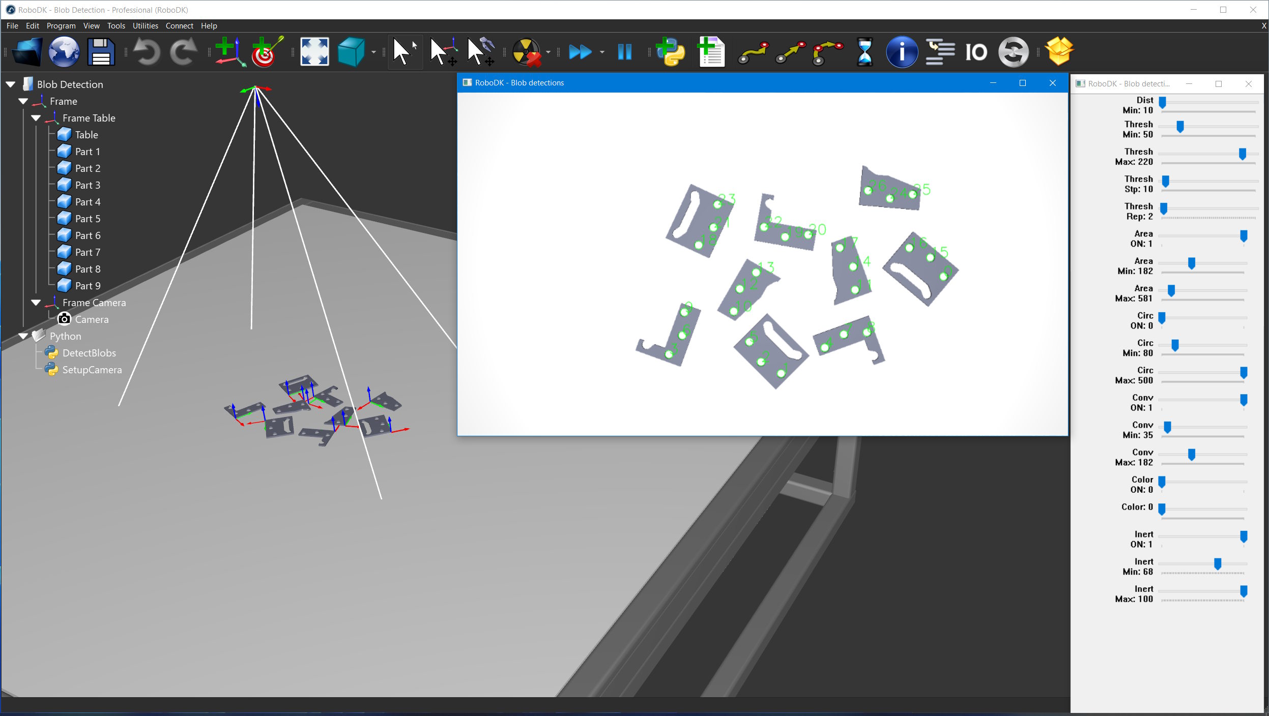
# Type help("robolink") or help("robodk") for more information
# Press F5 to run the script
# Documentation: https://robodk.com/doc/en/RoboDK-API.html
# Reference:     https://robodk.com/doc/en/PythonAPI/index.html
#
# This example shows how to detect blobs in a camera feed using OpenCV.
# It uses a simulated camera, but it can easily be modified to use an input camera.
#
# You can find more information in the OpenCV Contours tutorials:
# https://docs.opencv.org/master/d3/d05/tutorial_py_table_of_contents_contours.html

from robodk.robolink import *  # RoboDK API

import_install('cv2', 'opencv-python')
import cv2 as cv
import numpy as np

#----------------------------------
# Settings
PROCESS_COUNT = -1  # How many frames to process before exiting. -1 means indefinitely.

CAM_NAME = "Camera"

DISPLAY_SETTINGS = True
WDW_NAME_PARAMS = 'RoboDK - Blob detection parameters'

DISPLAY_RESULT = True
WDW_NAME_RESULTS = 'RoboDK - Blob detections'

#----------------------------------
# Get the simulated camera from RoboDK
RDK = Robolink()

cam_item = RDK.Item(CAM_NAME, ITEM_TYPE_CAMERA)
if not cam_item.Valid():
    raise Exception("Camera not found! %s" % CAM_NAME)
cam_item.setParam('Open', 1)  # Force the camera view to open

#----------------------------------------------
# Set up the detector with default parameters.
# Default parameters extract dark circular blobs.
global params
params = cv.SimpleBlobDetector_Params()
global detector
detector = cv.SimpleBlobDetector_create(params)

#----------------------------------------------
# Set up sliders for parameters, using OpenCV's trackbars
if DISPLAY_SETTINGS:

    cv.namedWindow(WDW_NAME_PARAMS, cv.WINDOW_FREERATIO | cv.WINDOW_GUI_EXPANDED)

    def minDistBetweenBlobs(value):
        """Minimum distance between two blobs, in pixels."""
        global params
        global detector
        params.minDistBetweenBlobs = value
        detector = cv.SimpleBlobDetector_create(params)

    # Image thresholds
    def minThreshold(value):
        """Minimum intensity threshold, in uint8."""
        global params
        global detector
        params.minThreshold = value
        detector = cv.SimpleBlobDetector_create(params)

    def maxThreshold(value):
        """Maximum intensity threshold, in uint8."""
        global params
        global detector
        params.maxThreshold = value
        detector = cv.SimpleBlobDetector_create(params)

    def thresholdStep(value):
        """Intensity threshold steps between min and max thresholds, in uint8."""
        global params
        global detector
        params.thresholdStep = max(1, value)
        detector = cv.SimpleBlobDetector_create(params)

    def minRepeatability(value):
        """Minimum number of detections of a blob throughout the thresholding steps."""
        global params
        global detector
        params.minRepeatability = max(1, value)
        detector = cv.SimpleBlobDetector_create(params)

    # Filter by Area
    def filterByArea(value):
        """Enable filtering by blob area."""
        global params
        global detector
        params.filterByArea = value != 0
        detector = cv.SimpleBlobDetector_create(params)

    def minArea(value):
        """Minimum blob area, in pixel^2."""
        global params
        global detector
        params.minArea = value
        detector = cv.SimpleBlobDetector_create(params)

    def maxArea(value):
        """Maximum blob area, in pixel^2."""
        global params
        global detector
        params.maxArea = value
        detector = cv.SimpleBlobDetector_create(params)

    # Filter by Circularity (4*pi*area / perimeter^2)
    def filterByCircularity(value):
        """Enable filtering by blob circularity."""
        global params
        global detector
        params.filterByCircularity = value != 0
        detector = cv.SimpleBlobDetector_create(params)

    def minCircularity(value):
        """Minimum blob circularity, in %."""
        global params
        global detector
        params.minCircularity = value / 100
        detector = cv.SimpleBlobDetector_create(params)

    def maxCircularity(value):
        """Maximum blob circularity, in %."""
        global params
        global detector
        params.maxCircularity = value / 100
        detector = cv.SimpleBlobDetector_create(params)

    # Filter by Convexity (area / area of blob convex hull)
    def filterByConvexity(value):
        """Enable filtering by blob convexity."""
        global params
        global detector
        params.filterByConvexity = value != 0
        detector = cv.SimpleBlobDetector_create(params)

    def minConvexity(value):
        """Minimum blob convexity, in %."""
        global params
        global detector
        params.minConvexity = value / 100
        detector = cv.SimpleBlobDetector_create(params)

    def maxConvexity(value):
        """Maximum blob convexity, in %."""
        global params
        global detector
        params.maxConvexity = value / 100
        detector = cv.SimpleBlobDetector_create(params)

    # Filter by Color (light vs. dark)
    def filterByColor(value):
        """Enable filtering by blob color."""
        global params
        global detector
        params.filterByColor = value != 0
        detector = cv.SimpleBlobDetector_create(params)

    def blobColor(value):
        """Color of the blob, in uint8."""
        global params
        global detector
        params.blobColor = value  # [0 (dark), 255 (light)]
        detector = cv.SimpleBlobDetector_create(params)

    # Filter by Inertia (elongation)
    def filterByInertia(value):
        """Enable filtering by blob inertia."""
        global params
        global detector
        params.filterByInertia = value != 0
        detector = cv.SimpleBlobDetector_create(params)

    def minInertiaRatio(value):
        """Minimum blob inertia, in %."""
        global params
        global detector
        params.minInertiaRatio = value / 100  # [0, 1]
        detector = cv.SimpleBlobDetector_create(params)

    def maxInertiaRatio(value):
        """Maximum blob inertia, in %."""
        global params
        global detector
        params.maxInertiaRatio = value / 100  # [0, 1]
        detector = cv.SimpleBlobDetector_create(params)

    # All ranges are from 0 to 'count', initialized at the default value.
    cv.createTrackbar('Dist\nMin', WDW_NAME_PARAMS, int(params.minDistBetweenBlobs), 999, minDistBetweenBlobs)
    cv.createTrackbar('Thresh\nMin', WDW_NAME_PARAMS, int(params.minThreshold), 255, minThreshold)
    cv.createTrackbar('Thresh\nMax', WDW_NAME_PARAMS, int(params.maxThreshold), 255, maxThreshold)
    cv.createTrackbar('Thresh\nStp', WDW_NAME_PARAMS, int(params.thresholdStep), 255, thresholdStep)
    cv.createTrackbar('Thresh\nRep', WDW_NAME_PARAMS, int(params.minRepeatability), 100, minRepeatability)
    cv.createTrackbar('Area\nON', WDW_NAME_PARAMS, bool(params.filterByArea), 1, filterByArea)
    cv.createTrackbar('Area\nMin', WDW_NAME_PARAMS, int(params.minArea), 500, minArea)
    cv.createTrackbar('Area\nMax', WDW_NAME_PARAMS, int(params.maxArea), 5000, maxArea)
    cv.createTrackbar('Circ\nON', WDW_NAME_PARAMS, bool(params.filterByCircularity), 1, filterByCircularity)
    cv.createTrackbar('Circ\nMin', WDW_NAME_PARAMS, int(params.minCircularity * 100), 500, minCircularity)
    cv.createTrackbar('Circ\nMax', WDW_NAME_PARAMS, int(min(500, params.maxCircularity * 100)), 500, maxCircularity)
    cv.createTrackbar('Conv\nON', WDW_NAME_PARAMS, bool(params.filterByConvexity), 1, filterByConvexity)
    cv.createTrackbar('Conv\nMin', WDW_NAME_PARAMS, int(params.minConvexity * 100), 500, minConvexity)
    cv.createTrackbar('Conv\nMax', WDW_NAME_PARAMS, int(min(500, params.maxConvexity * 100)), 500, maxConvexity)
    cv.createTrackbar('Color\nON', WDW_NAME_PARAMS, bool(params.filterByColor), 1, filterByColor)
    cv.createTrackbar('Color', WDW_NAME_PARAMS, int(params.blobColor), 255, blobColor)
    cv.createTrackbar('Inert\nON', WDW_NAME_PARAMS, bool(params.filterByInertia), 1, filterByInertia)
    cv.createTrackbar('Inert\nMin', WDW_NAME_PARAMS, int(params.minInertiaRatio * 100), 100, minInertiaRatio)
    cv.createTrackbar('Inert\nMax', WDW_NAME_PARAMS, int(min(100, params.maxInertiaRatio * 100)), 100, maxInertiaRatio)

#----------------------------------------------
# Create an resizable result window
if DISPLAY_RESULT:
    cv.namedWindow(WDW_NAME_RESULTS)  #, cv.WINDOW_NORMAL)

#----------------------------------------------
# Start a camera feed.
# If you are using a connected device, use cv.VideoCapture to get the livefeed.
# https://docs.opencv.org/master/d8/dfe/classcv_1_1VideoCapture.html
#
# capture = cv.VideoCapture(0)
# retval, image = capture.read()

#----------------------------------------------
# Process camera frames
count = 0
while count < PROCESS_COUNT or PROCESS_COUNT < 0:
    print("=============================================")
    print("Processing image %i" % count)
    count += 1

    #----------------------------------------------
    # Get the image from RoboDK
    bytes_img = RDK.Cam2D_Snapshot("", cam_item)
    if bytes_img == b'':
        raise
    # Image from RoboDK are BGR, uchar, (h,w,3)
    nparr = np.frombuffer(bytes_img, np.uint8)
    img = cv.imdecode(nparr, cv.IMREAD_UNCHANGED)
    if img is None or img.shape == ():
        raise

    #----------------------------------------------
    # Detect blobs
    keypoints = detector.detect(img)
    i = 0
    for keypoint in keypoints:
        print("id:%i  coord=(%0.0f, %0.0f)" % (i, keypoint.pt[0], keypoint.pt[1]))
        i += 1

    #----------------------------------------------
    # Do something with your detections!
    # Here's a few examples:
    # - Reject a part if the number of keypoints (screw holes) is different than 3
    # - Calculate the world coordinate of each keypoints to move the robot

    #----------------------------------------------
    # Display the detection to the user (reference image and camera image side by side, with detection results)
    if DISPLAY_RESULT:

        # Draw detected blobs and their id
        img_matches = cv.drawKeypoints(img, keypoints, None, (0, 255, 0), cv.DRAW_MATCHES_FLAGS_DRAW_RICH_KEYPOINTS)
        i = 0
        for keypoint in keypoints:
            x, y = keypoint.pt
            cv.putText(img_matches, str(i), (int(x), int(y)), cv.FONT_HERSHEY_SIMPLEX, 1, (0, 255, 0), 1, cv.LINE_AA)
            i += 1

        # Resize the image, so that it fits your screen
        img_matches = cv.resize(img_matches, (int(img_matches.shape[1] * .75), int(img_matches.shape[0] * .75)))

        cv.imshow(WDW_NAME_RESULTS, img_matches)
        key = cv.waitKey(500)
        if key == 27:
            break  # User pressed ESC, exit
        if cv.getWindowProperty(WDW_NAME_RESULTS, cv.WND_PROP_VISIBLE) < 1:
            break  # User killed the window, exit

cv.destroyAllWindows()
6.32.8.3. Orientation of elongated parts
This example shows how to detect the orientation of elongated parts in a camera feed using OpenCV. It uses a simulated camera, but it can easily be modified to use an input camera. You can find more information in the OpenCV contours tutorial.
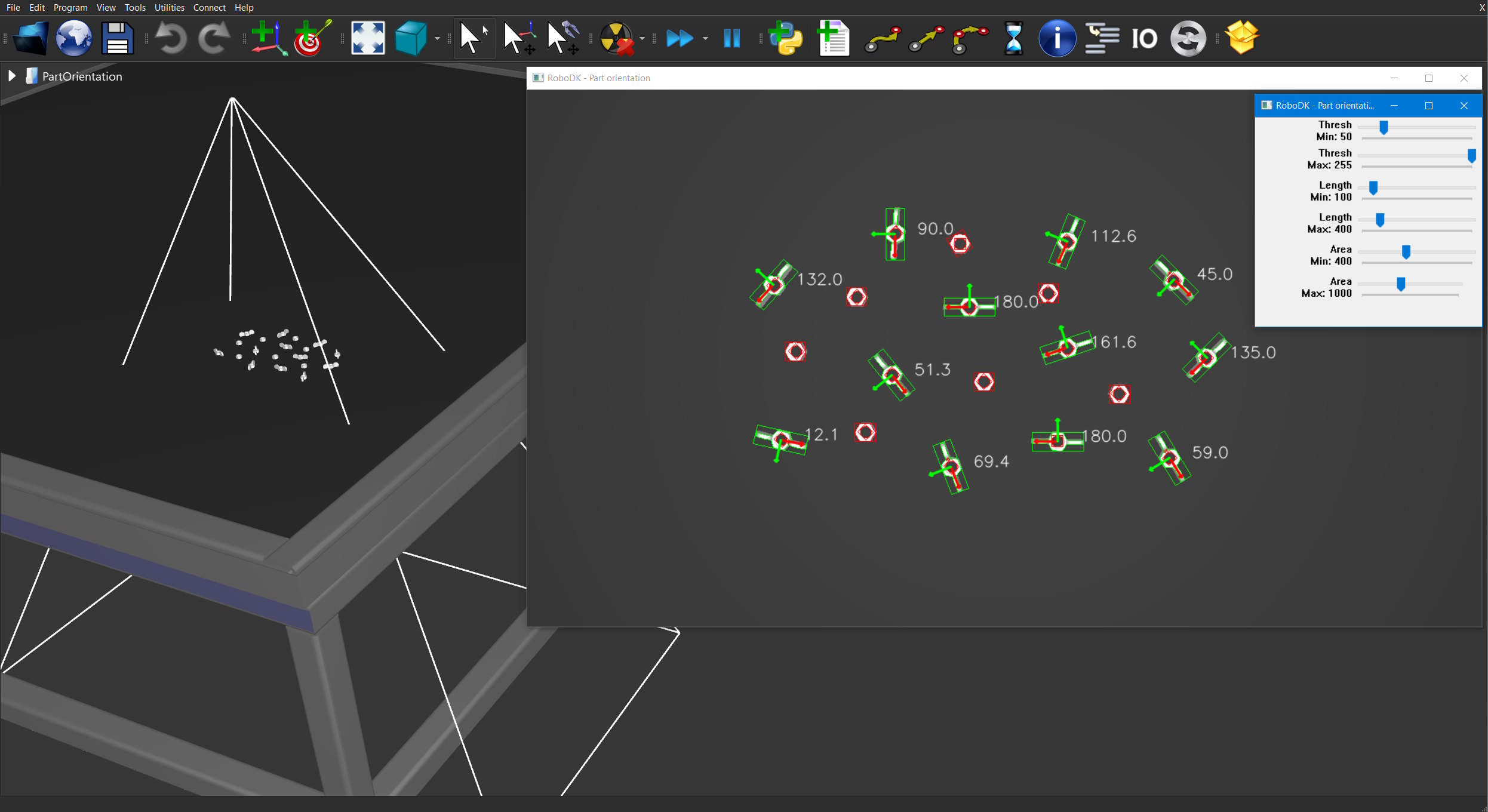
# Type help("robolink") or help("robodk") for more information
# Press F5 to run the script
# Documentation: https://robodk.com/doc/en/RoboDK-API.html
# Reference:     https://robodk.com/doc/en/PythonAPI/index.html
#
# This example shows how to detect the orientation of elongated parts in a camera feed using OpenCV.
# It uses a simulated camera, but it can easily be modified to use an input camera.
# Warning: best results are observe with elongated parts that are symmetrical.
#
# You can find more information in the OpenCV Contours tutorials:
# https://docs.opencv.org/master/d3/d05/tutorial_py_table_of_contents_contours.html

from robodk.robolink import *  # RoboDK API
from robodk.robomath import *  # Robot toolbox

import_install('cv2', 'opencv-contrib-python')
import cv2 as cv
import numpy as np

#----------------------------------
# Settings
PROCESS_COUNT = -1  # How many frames to process before exiting. -1 means indefinitely.

CAM_NAME = "Camera"

DISPLAY_SETTINGS = True
WDW_NAME_PARAMS = 'RoboDK - Part orientation parameters'

DISPLAY_RESULT = True
WDW_NAME_RESULTS = 'RoboDK - Part orientation'

DRAW_AXIS_LENGTH = 30

THRESH_MIN = 50
THRESH_MAX = 255
LENGTH_MIN = 100
LENGTH_MAX = 400
AREA_MIN = 400
AREA_MAX = 1000

#----------------------------------
# Get the simulated camera from RoboDK
RDK = Robolink()

cam_item = RDK.Item(CAM_NAME, ITEM_TYPE_CAMERA)
if not cam_item.Valid():
    raise Exception("Camera not found! %s" % CAM_NAME)
cam_item.setParam('Open', 1)  # Force the camera view to open

#----------------------------------------------
# Start a camera feed.
# If you are using a connected device, use cv.VideoCapture to get the livefeed.
# https://docs.opencv.org/master/d8/dfe/classcv_1_1VideoCapture.html
#
# capture = cv.VideoCapture(0)
# retval, image = capture.read()

#----------------------------------------------
# Create an resizable result window with sliders for parameters
if DISPLAY_RESULT:
    cv.namedWindow(WDW_NAME_RESULTS)

if DISPLAY_SETTINGS:

    def nothing(val):
        pass

    cv.namedWindow(WDW_NAME_PARAMS)
    cv.createTrackbar('Thresh\nMin', WDW_NAME_PARAMS, THRESH_MIN, 255, nothing)
    cv.createTrackbar('Thresh\nMax', WDW_NAME_PARAMS, THRESH_MAX, 255, nothing)
    cv.createTrackbar('Length\nMin', WDW_NAME_PARAMS, LENGTH_MIN, 1000, nothing)
    cv.createTrackbar('Length\nMax', WDW_NAME_PARAMS, LENGTH_MAX, 2500, nothing)
    cv.createTrackbar('Area\nMin', WDW_NAME_PARAMS, AREA_MIN, 1000, nothing)
    cv.createTrackbar('Area\nMax', WDW_NAME_PARAMS, AREA_MAX, 2500, nothing)

#----------------------------------------------
# Process camera frames
count = 0
while count < PROCESS_COUNT or PROCESS_COUNT < 0:
    count += 1

    #----------------------------------------------
    # Get the image from RoboDK (since 5.3.0)
    bytes_img = RDK.Cam2D_Snapshot("", cam_item)
    if bytes_img == b'':
        raise
    # Image from RoboDK are BGR, uchar, (h,w,3)
    nparr = np.frombuffer(bytes_img, np.uint8)
    img = cv.imdecode(nparr, cv.IMREAD_UNCHANGED)
    if img is None or img.shape == ():
        raise

    #----------------------------------------------
    # Retrieve the slider values for this iteration
    if DISPLAY_SETTINGS:
        THRESH_MIN = cv.getTrackbarPos('Thresh\nMin', WDW_NAME_PARAMS)
        THRESH_MAX = cv.getTrackbarPos('Thresh\nMax', WDW_NAME_PARAMS)
        LENGTH_MIN = cv.getTrackbarPos('Length\nMin', WDW_NAME_PARAMS)
        LENGTH_MAX = cv.getTrackbarPos('Length\nMax', WDW_NAME_PARAMS)
        AREA_MIN = cv.getTrackbarPos('Area\nMin', WDW_NAME_PARAMS)
        AREA_MAX = cv.getTrackbarPos('Area\nMax', WDW_NAME_PARAMS)

    #----------------------------------------------
    # The easiest way to extract features is to threshold their intensity with regards to their background
    # Optimal results with light parts on dark background, and vice-versa
    _, img_bw = cv.threshold(cv.cvtColor(img, cv.COLOR_BGR2GRAY), THRESH_MIN, THRESH_MAX, cv.THRESH_BINARY | cv.THRESH_OTSU)

    #----------------------------------------------
    # Find and parse all the contours in the binary image
    contours, _ = cv.findContours(img_bw, cv.RETR_LIST, cv.CHAIN_APPROX_NONE)
    for i, c in enumerate(contours):
        reject = False

        # Calculate contour's length (only works with CHAIN_APPROX_NONE)
        length = len(c)
        if length < LENGTH_MIN or length > LENGTH_MAX:
            reject = True

        # Calculate the contour's area
        area = cv.contourArea(c)
        if area < AREA_MIN or area > AREA_MAX:
            reject = True

        #----------------------------------------------
        # Create a bounding box of the contour
        rect = cv.minAreaRect(c)
        center = (rect[0][0], rect[0][1])
        width = rect[1][0]
        height = rect[1][1]
        angle = np.radians(rect[2])
        # Angle is [0, 90], and from the horizontal to the bottom left and bottom right edge of the box
        if width < height:
            angle += pi / 2.0
        if angle > pi:
            angle -= pi

        #----------------------------------------------
        # You can also bestfit an ellipse and use it's angle
        #if length > 4:
        #    ell = cv.fitEllipse(c)
        #    center = (ell[0][0], ell[0][1])
        #    width = ell[1][0]
        #    height = ell[1][1]
        #    angle = np.radians(ell[2])
        #    if width < height2:
        #        angle += pi / 2.0
        #    if angle2 > pi:
        #        angle -= pi

        #----------------------------------------------
        # Do something with your detections!
        # Here's a few examples:
        # - Reject a part if it's orientation is different than expected
        # - Reject a part if it's area is too small
        # - Calculate the robot's rotation angle to pick a part

        #----------------------------------------------
        # Display the detection to the user (reference image and camera image side by side, with detection results)
        if DISPLAY_RESULT:
            color = (0, 255, 0)
            if reject:
                color = (0, 0, 255)

            # Draw the bounding box
            box = cv.boxPoints(rect)
            box = np.int0(box)
            cv.drawContours(img, [box], 0, color, 1)

            # Draw the contour
            cv.drawContours(img, contours, i, color, 1)

            if not reject:

                def rotate(origin, point, angle):
                    """Rotate a point counterclockwise by a given angle (radians) around a given origin."""
                    ox, oy = origin
                    px, py = point
                    qx = ox + math.cos(angle) * (px - ox) - math.sin(angle) * (py - oy)
                    qy = oy + math.sin(angle) * (px - ox) + math.cos(angle) * (py - oy)
                    return qx, qy

                # Construct the Axis parameters
                center_pt = center
                x_axis = (center_pt[0] + DRAW_AXIS_LENGTH, center_pt[1])
                x_axis = rotate(center_pt, x_axis, angle)
                y_axis = rotate(center_pt, x_axis, pi / 2.0)

                center_pt = (int(center_pt[0]), int(center_pt[1]))
                x_axis = (int(x_axis[0]), int(x_axis[1]))
                y_axis = (int(y_axis[0]), int(y_axis[1]))

                # Draw the orientation vector
                cv.circle(img, center_pt, 2, (255, 0, 0), -1)
                cv.arrowedLine(img, center_pt, x_axis, (0, 0, 255), 2, cv.LINE_AA)
                cv.arrowedLine(img, center_pt, y_axis, (0, 255, 0), 2, cv.LINE_AA)

                # Draw the angle
                label = '%0.1f' % np.degrees(angle)
                cv.putText(img, label, (center_pt[0] + 30, center_pt[1]), cv.FONT_HERSHEY_SIMPLEX, 0.7, (255, 255, 255), 1, cv.LINE_AA)

    cv.imshow(WDW_NAME_RESULTS, img)
    key = cv.waitKey(1)
    if key == 27:
        break  # User pressed ESC, exit
    if cv.getWindowProperty(WDW_NAME_RESULTS, cv.WND_PROP_VISIBLE) < 1:
        break  # User killed the main window, exit

cv.destroyAllWindows()
6.33. Depth Camera (3D)
6.33.1. Depth map
This example shows how to retrieve and display the 32-bit depth map of a simulated camera.
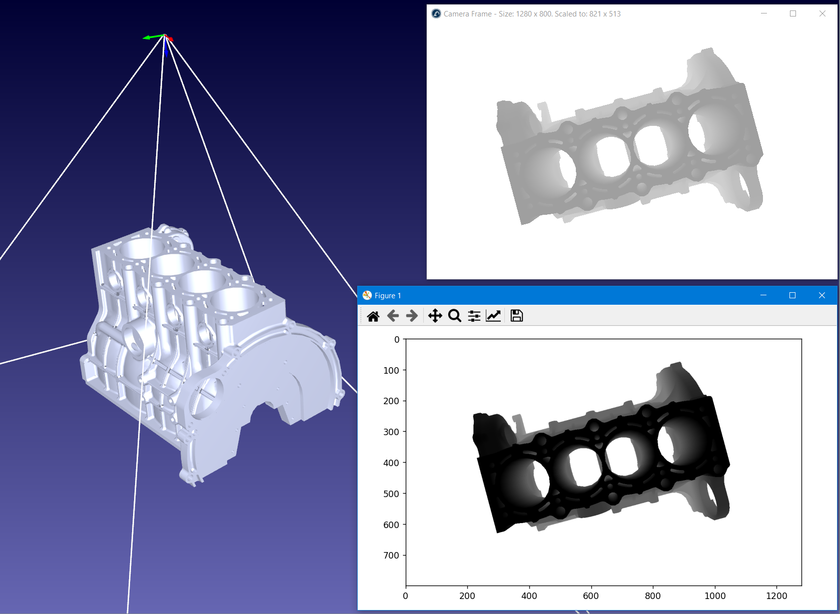
# Type help("robolink") or help("robodk") for more information
# Press F5 to run the script
# Documentation: https://robodk.com/doc/en/RoboDK-API.html
# Reference:     https://robodk.com/doc/en/PythonAPI/index.html
#
# This example shows how to retrieve and display the 32-bit depth map of a simulated camera.

from robodk.robolink import *  # RoboDK API

from tempfile import TemporaryDirectory
import numpy as np
from matplotlib import pyplot as plt

#----------------------------------
# Get the simulated camera from RoboDK
RDK = Robolink()

cam_item = RDK.Item('Depth Camera', ITEM_TYPE_CAMERA)
if not cam_item.Valid():
    cam_item = RDK.Cam2D_Add(RDK.ActiveStation(), 'DEPTH')
    cam_item.setName('Depth Camera')
cam_item.setParam('Open', 1)

#----------------------------------------------
# Get the image from RoboDK
td = TemporaryDirectory(prefix='robodk_')
tf = td.name + '/temp.grey32'
if RDK.Cam2D_Snapshot(tf, cam_item) == 1:
    grey32 = np.fromfile(tf, dtype='>u4')
    w, h = grey32[:2]
    grey32 = np.flipud(np.reshape(grey32[2:], (h, w)))
else:
    raise

#----------------------------------------------
# Display
grey32[grey32 == 0] = 2**32 - 1  # This is for display purposes only! Values of 0 do not have any measurements.
plt.imshow(grey32, 'gray')
plt.show()
6.33.2. Mesh reconstruction
This example shows how to convert a depth map into a mesh object using Open3D. Using the Stanford Bunny and a RoboDK simulated camera, you can extract the 32-bit depth map, convert it into a point cloud, approximate a mesh, visualize it in a 3D Viewer and import the object back into RoboDK.
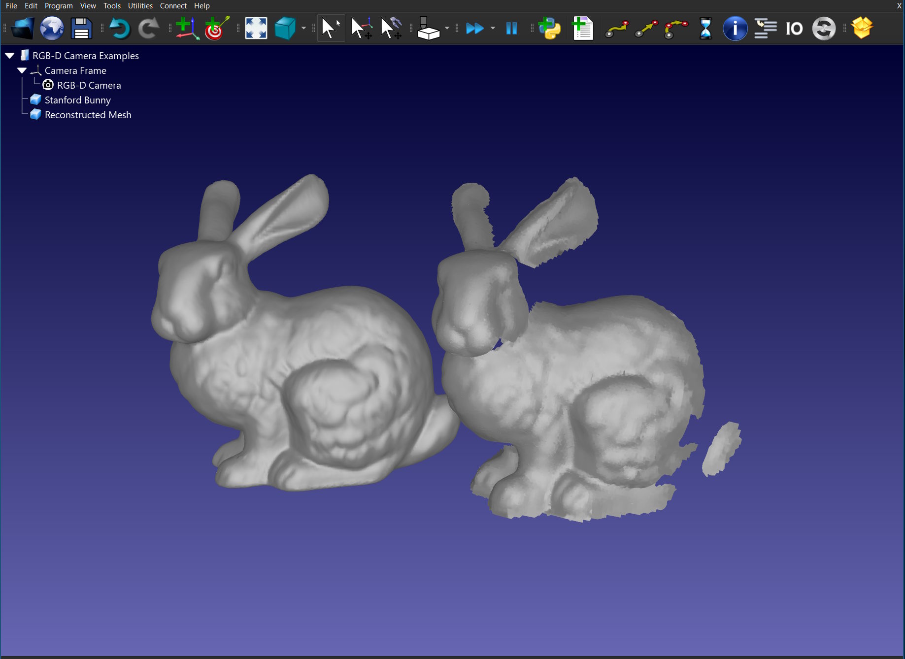
# Type help("robolink") or help("robodk") for more information
# Press F5 to run the script
# Documentation: https://robodk.com/doc/en/RoboDK-API.html
# Reference:     https://robodk.com/doc/en/PythonAPI/index.html
#
# This example shows how to reconstruct a mesh from the 32-bit depth map of a simulated camera.
# It uses Open3D for converting the depth map to a point cloud, to reconstruct the mesh and for vizualisation.
# Left-click the view to move the mesh in the viewer.

from robodk.robolink import *
from tempfile import TemporaryDirectory
import numpy as np
import open3d as o3d

#----------------------------------
# You might need to play arround these settings depending on the object/setup
CAMERA_NAME = 'RGB-D Camera'

O3D_NORMALS_K_SIZE = 100
O3D_MESH_POISSON_DEPTH = 9
O3D_MESH_DENSITIES_QUANTILE = 0.05
O3D_DISPLAY_POINTS = False
O3D_DISPLAY_WIREFRAME = True

#----------------------------------
# Get the simulated camera from RoboDK
RDK = Robolink()

cam_item = RDK.Item(CAMERA_NAME, ITEM_TYPE_CAMERA)
if not cam_item.Valid():
    cam_item = RDK.Cam2D_Add(RDK.ActiveStation())
    cam_item.setName(CAMERA_NAME)
cam_item.setParam('Open', 1)


#----------------------------------
# Retrieve camera settings / camera matrix
def settings_to_dict(settings):
    if not settings:
        return {}

    settings_dict = {}
    settings_list = [setting.split('=') for setting in settings.strip().split(' ')]
    for setting in settings_list:
        key = setting[0].upper()
        val = setting[-1]

        if key in ['FOV', 'PIXELSIZE', 'FOCAL_LENGTH', 'FAR_LENGTH']:
            val = float(val)
        elif key in ['SIZE', 'ACTUALSIZE', 'SNAPSHOT']:
            w, h = val.split('x')
            val = (int(w), int(h))
        elif key == val.upper():
            val = True  # Flag

        settings_dict[key] = val

    return settings_dict


cam_settings = settings_to_dict(cam_item.setParam('Settings'))
w, h = cam_settings['SIZE']
fy = h / (2 * np.tan(np.radians(cam_settings['FOV']) / 2))
cam_mtx = o3d.camera.PinholeCameraIntrinsic(width=w, height=h, fx=fy, fy=fy, cx=w / 2, cy=h / 2)
cam_pose = cam_item.getLink(ITEM_TYPE_FRAME).Pose()

#----------------------------------------------
# Get the depth map

# Method 1: by socket (requires RoboDK v5.4.3-2022-06-20)
depth32_socket = None
bytes_img = RDK.Cam2D_Snapshot("", cam_item, 'DEPTH')
if isinstance(bytes_img, bytes) and bytes_img != b'':
    # By socket
    depth32_socket = np.frombuffer(bytes_img, dtype='>u4')
    w, h = depth32_socket[:2]
    depth32_socket = np.flipud(np.reshape(depth32_socket[2:], (h, w))).astype(np.uint32)

# Method 2: from disk
depth32_disk = None
with TemporaryDirectory(prefix='robodk_') as td:
    tf = td + '/temp.grey32'
    if RDK.Cam2D_Snapshot(tf, cam_item, 'DEPTH') == 1:
        depth32_disk = np.fromfile(tf, dtype='>u4')
        w, h = depth32_disk[:2]
        depth32_disk = np.flipud(np.reshape(depth32_disk[2:], (h, w))).astype(np.uint32)

# Scale it
depth = (depth32_socket / np.iinfo(np.uint32).max) * cam_settings['FAR_LENGTH']
depth = depth.astype(np.float32)

#----------------------------------------------
# Convert to point cloud, approximate mesh
pcd = o3d.geometry.PointCloud.create_from_depth_image(o3d.geometry.Image(depth), cam_mtx)
pcd.transform([[1, 0, 0, 0], [0, -1, 0, 0], [0, 0, -1, 0], [0, 0, 0, 1]])  # Align with camera view
pcd.estimate_normals()
pcd.orient_normals_consistent_tangent_plane(O3D_NORMALS_K_SIZE)

mesh_poisson, densities = o3d.geometry.TriangleMesh.create_from_point_cloud_poisson(pcd, depth=O3D_MESH_POISSON_DEPTH)
vertices_to_remove = densities < np.quantile(densities, O3D_MESH_DENSITIES_QUANTILE)
mesh_poisson.remove_vertices_by_mask(vertices_to_remove)
mesh_poisson.paint_uniform_color([0.5, 0.5, 0.5])

#----------------------------------------------
# Show it to the world!
o3d.visualization.draw_geometries([pcd, mesh_poisson] if O3D_DISPLAY_POINTS else [mesh_poisson], mesh_show_back_face=True, mesh_show_wireframe=O3D_DISPLAY_WIREFRAME)

#----------------------------------------------
# Import the mesh into RoboDK
with TemporaryDirectory(prefix='robodk_') as td:
    tf = td + '/mesh.ply'
    o3d.io.write_triangle_mesh(tf, mesh_poisson, write_ascii=True)
    mesh_item = RDK.AddFile(tf)

mesh_item.setPose(cam_pose * robomath.rotx(robomath.pi))
mesh_item.setColor([0.5, 0.5, 0.5, 1])
mesh_item.setName("Reconstructed Mesh")
6.33.3. RGB-D Livestream
This example shows how to visualize a RGB-D camera in 3D using Open3D. Using the Stanford Bunny and a RoboDK simulated camera, you can extract the 32-bit depth map, convert it into a point cloud and visualize it in a 3D Viewer.
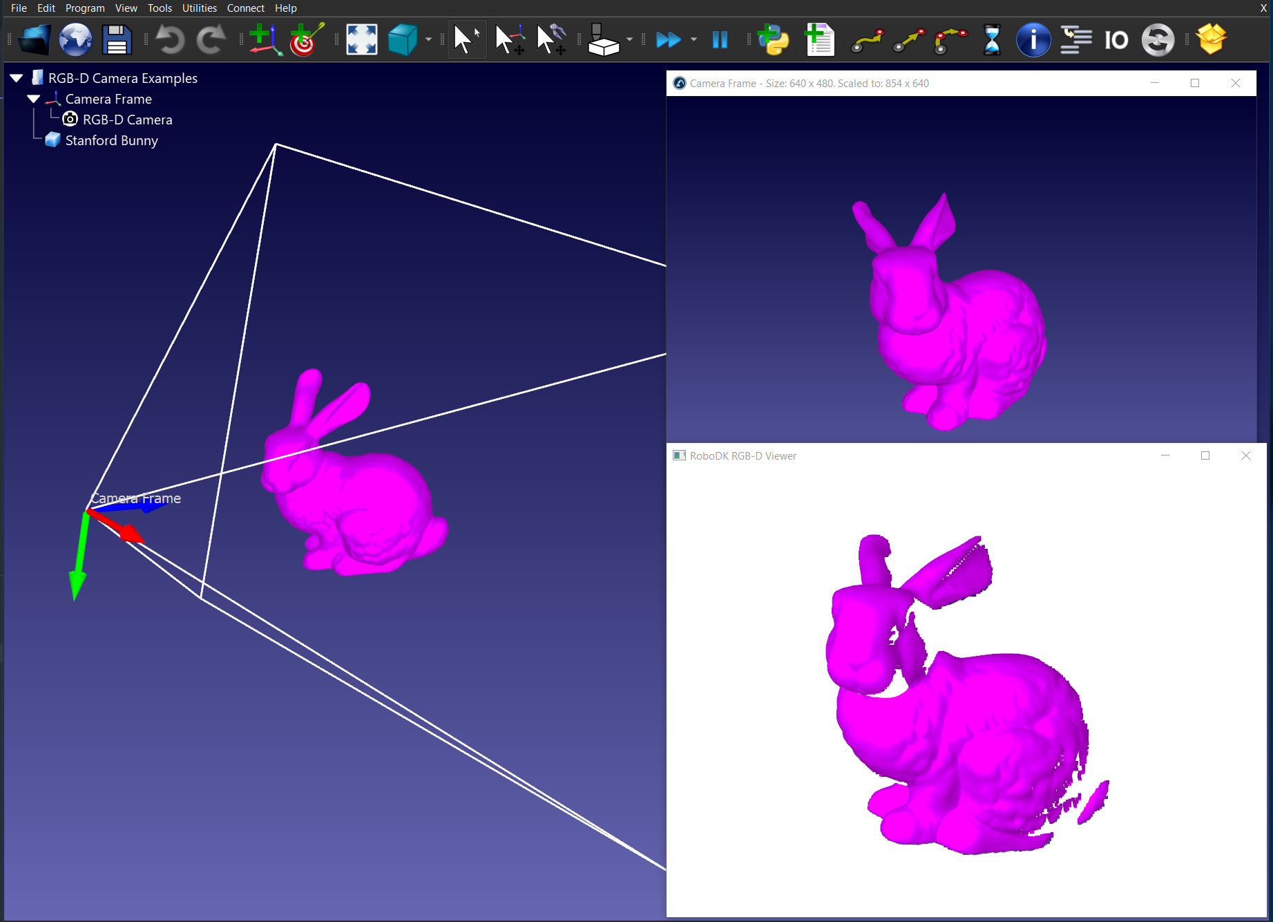
# Type help("robolink") or help("robodk") for more information
# Press F5 to run the script
# Documentation: https://robodk.com/doc/en/RoboDK-API.html
# Reference:     https://robodk.com/doc/en/PythonAPI/index.html
#
# This example shows how to retrieve both the RGB and Depth images to vizualize colorized point cloud in 3D using a simulated camera.
# It uses Open3D for converting the depth map to a point cloud and for vizualisation.
# Left-click the view to move the mesh in the viewer.

from robodk.robolink import *
import numpy as np
import open3d as o3d
import cv2 as cv

#----------------------------------
# You might need to play arround these settings depending on the object/setup
CAMERA_NAME = 'RGB-D Camera'
ANIMATE_OBJECT = True

#----------------------------------
# Get the simulated camera from RoboDK
RDK = Robolink()

cam_item = RDK.Item(CAMERA_NAME, ITEM_TYPE_CAMERA)
if not cam_item.Valid():
    cam_item = RDK.Cam2D_Add(RDK.ActiveStation())  # Do not set the DEPTH option here, as we are retrieving both RGB and DEPTH images
    cam_item.setName(CAMERA_NAME)
cam_item.setParam('Open', 1)

#----------------------------------
# Get the scanned object, to rotate it arround
obj_item = RDK.ItemUserPick(itemtype_or_list=ITEM_TYPE_OBJECT)
if not obj_item.Valid():
    obj_item = None


#----------------------------------
# Retrieve camera settings / camera matrix
def settings_to_dict(settings):
    if not settings:
        return {}

    settings_dict = {}
    settings_list = [setting.split('=') for setting in settings.strip().split(' ')]
    for setting in settings_list:
        key = setting[0].upper()
        val = setting[-1]

        if key in ['FOV', 'PIXELSIZE', 'FOCAL_LENGTH', 'FAR_LENGTH']:
            val = float(val)
        elif key in ['SIZE', 'ACTUALSIZE', 'SNAPSHOT']:
            w, h = val.split('x')
            val = (int(w), int(h))
        elif key == val.upper():
            val = True  # Flag

        settings_dict[key] = val

    return settings_dict


cam_settings = settings_to_dict(cam_item.setParam('Settings'))
w, h = cam_settings['SIZE']
fy = h / (2 * np.tan(np.radians(cam_settings['FOV']) / 2))

cam_params = o3d.camera.PinholeCameraParameters()
cam_params.intrinsic = o3d.camera.PinholeCameraIntrinsic(width=w, height=h, fx=fy, fy=fy, cx=w / 2, cy=h / 2)

#----------------------------------
# Initialize a non-blocking 3D viewer
vis = o3d.visualization.Visualizer()
vis.create_window("RoboDK RGB-D Viewer")
source = None

i = 0
while True:

    #----------------------------------------------
    # Get the RDB+D image from RoboDK

    # Get the RGB image
    rgb = None
    bytes_img = RDK.Cam2D_Snapshot("", cam_item)
    if not isinstance(bytes_img, bytes) or bytes_img == b'':
        continue
    nparr = np.frombuffer(bytes_img, np.uint8)
    rgb = cv.imdecode(nparr, cv.IMREAD_ANYCOLOR)
    rgb = cv.cvtColor(rgb, cv.COLOR_RGB2BGR)

    # Get the Depth image
    depth32 = None
    bytes_img = RDK.Cam2D_Snapshot("", cam_item, 'DEPTH')
    if not isinstance(bytes_img, bytes) or bytes_img == b'':
        continue
    depth32 = np.frombuffer(bytes_img, dtype='>u4')
    w, h = depth32[:2]
    depth32 = np.flipud(np.reshape(depth32[2:], (h, w))).astype(np.uint32)
    depth = (depth32 / np.iinfo(np.uint32).max) * cam_settings['FAR_LENGTH']
    depth = depth.astype(np.float32)

    rgbd_image = o3d.geometry.RGBDImage.create_from_color_and_depth(o3d.geometry.Image(rgb), o3d.geometry.Image(depth), convert_rgb_to_intensity=False)

    #----------------------------------------------
    # Convert to point cloud
    pcd = o3d.geometry.PointCloud.create_from_rgbd_image(rgbd_image, cam_params.intrinsic)
    pcd.transform([[1, 0, 0, 0], [0, -1, 0, 0], [0, 0, -1, 0], [0, 0, 0, 1]])

    #----------------------------------------------
    # Update the viewer
    if source is None:
        source = pcd
    else:
        source.points = pcd.points
        source.colors = pcd.colors

    if i == 0:
        vis.add_geometry(source, reset_bounding_box=True)
    else:
        vis.update_geometry(source)
        if not vis.poll_events():
            break
        vis.update_renderer()

    #----------------------------------------------
    # Rainbow color cycle and rotate the object
    if ANIMATE_OBJECT and obj_item:
        obj_item.setPose(obj_item.Pose() * robomath.rotz(0.05))

        import colorsys
        r, g, b = colorsys.hsv_to_rgb(i % 100 / 100, 1, 1)
        obj_item.setColor([r, g, b, 1])

    i += 1