Generate calibration targets
There are four sets of measurements that are required to successfully accomplish robot calibration:
1.Base setup: six measurements (or more) moving axis 1 and 2 are required to place the calibration reference with respect to the robot. Select Show in the calibration settings window and the robot will move along the sequence.
2.Tool setup: seven or more measurements are required to calibrate the tool flange and the tool targets (moving axis 5 and 6). Select Show and the robot will move along the sequence.
3.Calibration measurements: 60 measurements or more are required to calibrate the robot. These measurements can be randomly placed in the robot workspace and free of collision with the surrounding objects.
4.Validation measurements (optional): as many measurements as desired can be used to validate the robot accuracy. These measurements are used only to validate the accuracy of the robot and not to calibrate the robot.
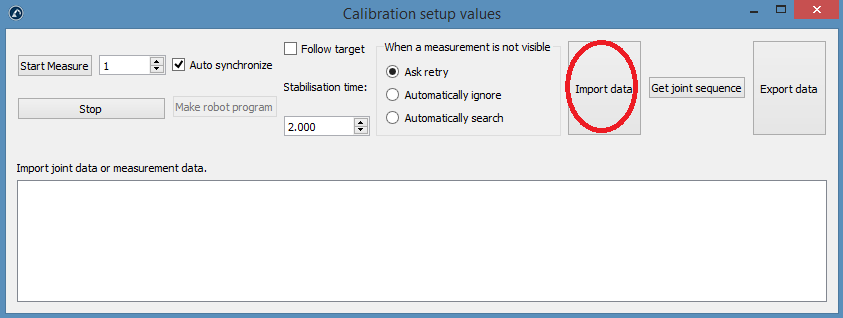
The first two sets of measurements are automatically generated by RoboDK. Select Show and the robot will follow the sequence (as shown in the following images). If the sequence needs to be changed, select Measure and export the calibration measurements as a CSV file by selecting Export data. This file can be edited using an Excel sheet and re-imported by clicking Import data.
The last two sets of measurements (calibration and validation) can be generated using the macro script called “
●Number of measurements: The number of measurements to generate. By default, 80 measurements are used because a minimum of 60 measurements is required for robot calibration.
●Reference position: The reference position must be a position of the robot where the tool is facing the tracker with visible targets.
●Joint limits: The lower and upper joint limits must be provided.
●Cartesian limits: You can provide Cartesian limits (X,Y,Z values) with respect to the robot reference frame.
The script automatically generates measurements where the tool is facing the tracker as well as respecting the joint and Cartesian constrains. A rotation of +/-180 deg around the tool is permitted around the direction that faces the tracker at the reference position. Furthermore, the sequence of joint movements is free of collision and inside the measurement workspace (if the workspace is set to be visible). The following image shows the summary that is presented to the user before the automatic sequence starts. It may take up to 5 minutes for the sequence to finish.
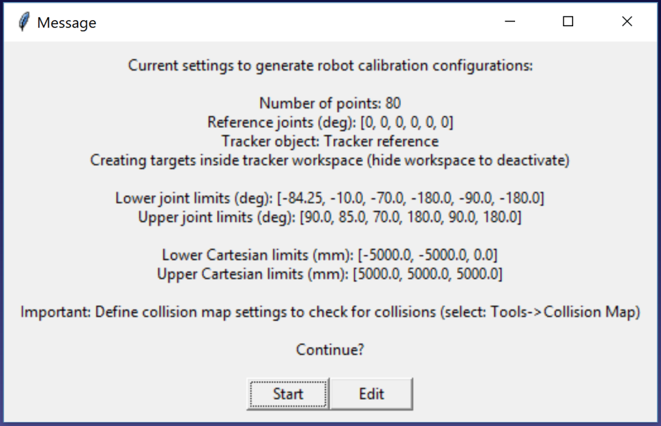
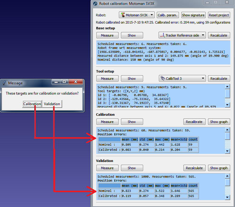
A new message will pop up once the algorithm finishes. Select Calibration to use the 60 measurements for robot calibration. You can re-execute the same script to generate another set of measurements for validation. This step is optional but 60 measurements ore more are recommended for validation purposes.
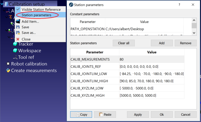
If desired, you can modify the script by right clicking the Create measurements script and selecting Edit script, then, modify additional parameters of the algorithm. The script automatically saves the user input as station parameters. You can view, edit or delete these settings by right clicking the station and selecting Station parameters, as shown in the next image.
Finally, it is also possible to import configurations that have been selected manually by selecting Import data (inside the Measure menu). You can import a CSV or a TXT file as an Nx6 matrix, where N is the number of configurations.