RoboDK station
A RoboDK station is where the virtual environment station and calibration information is stored. The station is saved as an RDK file. Follow the next steps to create a robot station for robot calibration from scratch (video preview: https://youtu.be/Nkb9uDamFb4):
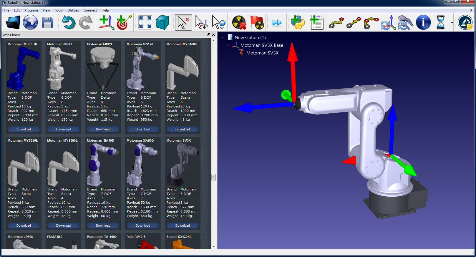
1.Select the robot:
a.Select File➔Open Robot library. The online library will open in your browser.
b.Use the filters to find your robot by name, brand, payload, ...
c.Select Open and the robot should automatically appear in your open RoboDK project.
d.Alternatively, you can download the robot files (.robot file) from http://robodk.com/library and open them with RoboDK.
1.Prepare your project for robot calibration:
a.Add reference frames by selecting Program➔Add Reference Frame.
i.One “Measurements reference” frame must be added with respect to the robot base frame.
ii.One “Tracker reference” must be added with respect to the “Measurements reference” that you just added.
iii.One additional “Tool reference” can be optionally added with respect to the “Measurements reference” frame to visualize the position of the tool seen by the tracker.
Tip 1: Drag and drop items in the tree to reconstruct the dependency that exists in the real world. For example, the tracker reference must be placed with respect to the “Measurements Reference”.
Tip 2: you can approximately move any reference frames or tool frames by holding the ALT key and SHIFT+ALT key respectively. Alternatively, you can double click the reference frame and input the right coordinates.
Tip 3: Rename any object by pressing the F2 key when the item is selected in the tree.
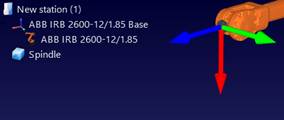
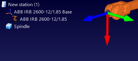
b.Add the tool object (STL, IGES and STEP files are supported formats) and drag and drop it to the robot (within the item tree), this will automatically convert the object into a tool. More information available here.
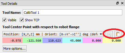
Optional: Select Program➔Add Tool (TCP) to add any TCP’s that you want to visualize in the station (to check for collisions or other). To set an approximate value of the TCP:
i.Double click the new tool.
ii.Set an approximate TCP value. You can copy/paste the 6 values at once using the two buttons at the right.
iii.It is recommended to rename the TCPs used for calibration with the name “CalibTool id”, where id is the calibration target number.
c.Add other 3D CAD files (STL, IGES, STEP, SLD, ...) to model the virtual station using the menu File➔Open… Alternatively, drag and drop files to RoboDK’s main window.
Tip 1: Import the 3D files of the measurement workspace and name it Workspace so that the robot measurements are generated inside the workspace of the tracker. Alternatively, set the workspace invisible if you do not want to constrain the measurements inside the tracker workspace. More information is available in the next section.
Tip 2: It is possible to select CTRL+ALT+Shift+P to block exporting confidential 3D files that have been imported in RoboDK.
2.Add the calibration module in the station:
a.Select the menu Utilities➔Calibrate Robot.
b.Select Poses (6 DOF).
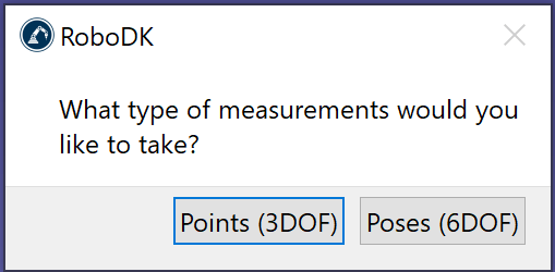
Then, the following window will appear.
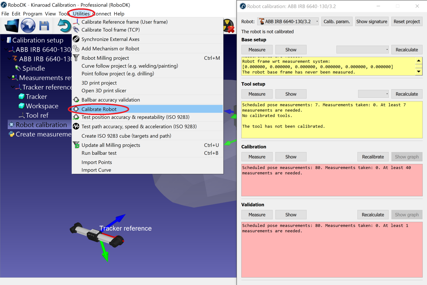
This window can be closed for now. You can open it anytime by double clicking the Robot calibration station item.
3.Save the station.
a.Select File➔Save Station.
b.Select a folder and choose a file name.
c.Select save. A new RDK file will be generated (RoboDK station file).
You can recover the station modifications anytime by opening the RDK file (double click the file).
Summarizing, it is important to double check the following points:
1.The reference frame “Measurements reference” should be directly attached to the robot base reference frame.
For now, you can use an estimate of this reference frame (approximate value).
2.The Tracker reference should be directly attached to the Measurements reference. The tracker reference must be an estimated position of the tracker measurement device with respect to the measurements reference. The base setup will find the exact position of the tracker.
3.The “Robot calibration” project is present in the station and all the measurements that you are planning to take are free of collision and visible by the tracker (double click the calibration settings and select show for each group of the four group of measurements).
4.If you want to automatically check for collisions you must use the name tag “collision” in every object that you want to use to check collisions. It is recommended to use a tool around 25% bigger than the calibrated tool to safely avoid collisions.