Robot calibration setup
You should make sure you have a proper setup to obtain the best accuracy after calibration.
You should first connect the laser tracker. You can optionally connect your robot to the computer to fully automate the procedure of taking measurements.
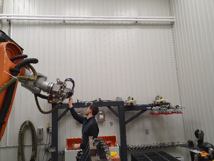
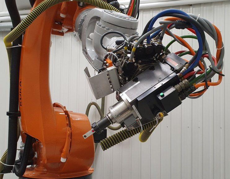
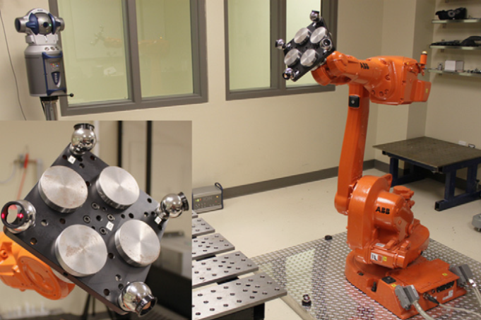
Also, make sure to attach at least one SMR target as shown in the following images. One SMR should be enough to have accurate results. We recommend you place the SMR target close to the TCP of interest. For example, if you are going to use your robot for robot machining, you could try placing one SMR on the cutting axis of your spindle.
Connect to the tracker
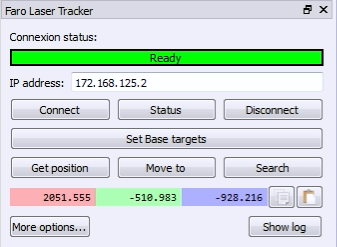
The IP of the laser tracker is needed to properly set the communication with RoboDK. Follow these steps to verify the communication with the laser tracker:
a.Select the menu « Connect➔Connect laser tracker ». A new window should open.
b.Set the IP of the laser tracker.
c.Click the “Connect” button.
If the connection is successful you should see a green message showing “Ready”. The window can be closed and the connection will remain active.
Connect to the robot
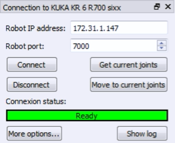
The IP of the robot (or the COM port number for RS232 connections) is needed to properly set the communication with RoboDK. Follow these steps to verify the communication with the robot:
1.Select Connect➔Connect robot. A new window will appear.
2.Set the IP and port of the robot (or the COM port if the connection is through RS232).
3.Click the Connect button.
4.Refer to the appendix if any problems arise.
If the connection is successful, you should see a green message displaying Ready. The position of the virtual robot should exactly match the position of the real robot if you select Get Position. Alternatively, select Move Joints to move the robot to the current position in the simulator. You can close this side window for now and the connection will remain active.

Measuring the reference targets
You can use a calibration reference frame if you are planning to move the laser tracker during the calibration or you would like to recover mastering for axis 1.
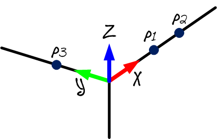
The calibration reference should be attached to the robot base, this will be helpful if you want to move the tracker during calibration or compare two robot calibrations. The calibration reference frame must be defined by 3 tangible points or SMRs.
You can skip this step if you are not going to move the tracker with respect to the robot or you don’t need to recover the home position for axis 1. In this case, the reference of the laser tracker will be used.
You should follow these steps every time the laser tracker is moved:
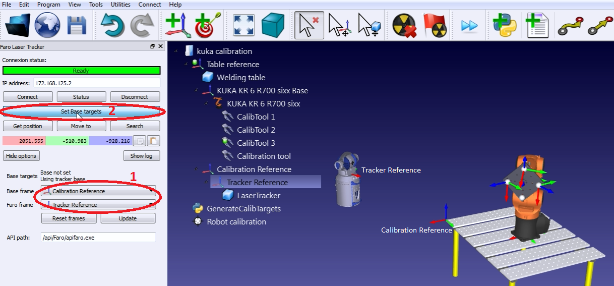
1.Select Connect➔Connect Faro Laser Tracker. Or the corresponding tracker you have.
2.Set the IP of the laser tracker and select connect (if laser tracker is not connected).
3.Set the calibration reference and the tracker reference as shown in the image. The calibration reference is also known as “Measurements reference”.
4.Select Set Base targets.
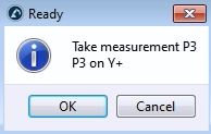
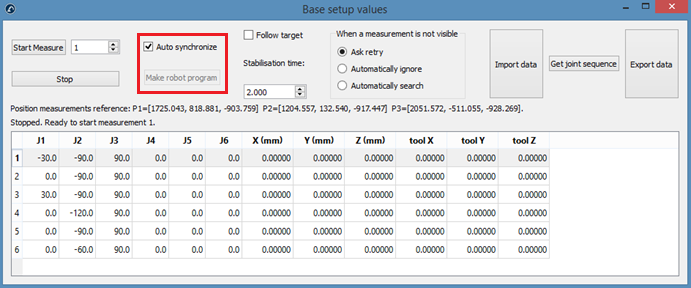
RoboDK will guide the user with the menus shown in the next image. The position of the laser tracker will be updated automatically with respect to the calibration reference when the procedure is completed.