Robot calibration
Robot calibration is divided in 4 steps. Each step requires taking a set of measurements. These four steps must be followed in order:
1.Base reference measurements (3 minutes).
2.Tool reference measurements (3 minutes).
3.Calibration measurements (7 minutes, 60 measurements).
4.Validation measurements (7 minutes, 60 measurements).
The following video shows how to perform this calibration in 20 minutes: https://www.robodk.com/robot-calibration#tab-lt. The validation measurements (step 4) are not mandatory to calibrate the robot, however they provide an objective point of view of the accuracy results. It is also possible to see the impact of calibrating the robot in one area and validating it in a different area.
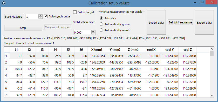
Select the button Measure for each of the four sets of measurements. This will open a new window that allows taking new measurements as well as import and export existing measurements in a text file (csv or txt format).
By default, the robot and measurement system are automatically synchronized through the connected robot. If a robot driver is not available, you can still perform robot calibration by generating a robot program which will prompt the user on the teach pendant for manual synchronization.
1.Uncheck Auto synchronize.
2.Click on the Make robot program button.
3.Use the proper post processor to generate the robot program.
Measuring the base
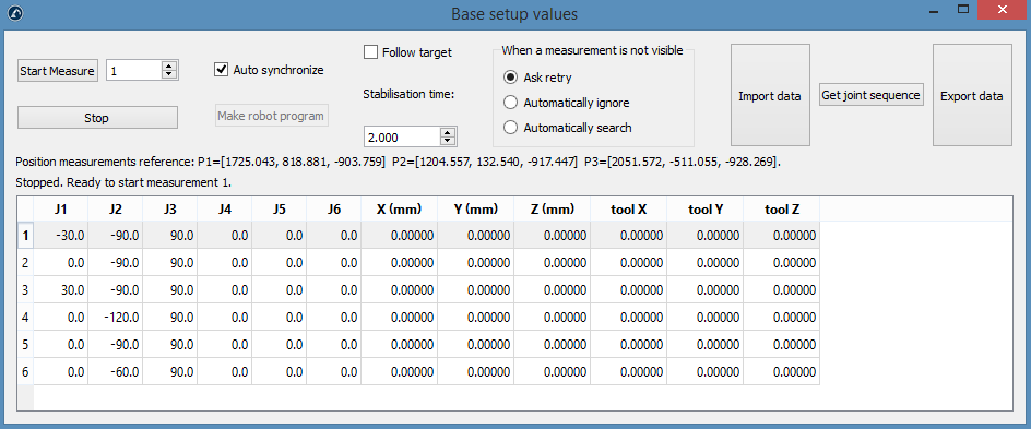
These measurements can be performed anywhere in the tool flange if you measure the same target for all the 6 measurements. To start the measurements, select Measure in the Base setup section. The following window will open. Then, select Start Measure and the robot will move sequentially through the scheduled measurements.
Close the window when the measurements are completed, and the Measurements reference frame will be updated with respect to the robot base frame. If you didn’t select any reference frame, you can add a reference (select Program➔Add Reference Frame) and place it under the robot base reference (Drag & Drop in the item tree).
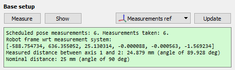
The summary will show the position and orientation or the robot reference frame with respect to the calibration reference frame ([x,y,z,w,p,r] format in mm and radians)
Measuring the tool
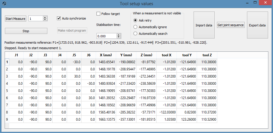
Measurements 1-6 can be performed anywhere in the tool flange as long as you measure the same target for the 6 measurements. After that, every TCP that you want to measure will add one measurement for the same TCP, in this case, you have 3 TCPs so 6+3=9 measurements in total. You can double click a measurement to continue measuring from that position.
Like the previous section: select Measure in the Tool setup section. The following window will open. Select Start Measure and the robot will move sequentially through the planned measurements. Double click a measurement to continue measuring from that position.
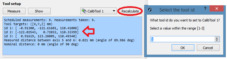
The summary will show the calibrated TCPs when the procedure is completed. The definition of the TCP (in the following image “CalibTool 1”) will be updated automatically. If you didn’t select any TCP, you can add a new one (select “Program➔Add empty Tool”) and select “Recalculate”. A new window will appear, and you must select the “id” of the tool depending on the order that you took the measurements. You can repeat the same procedure to update as many TCPs as you need (in this case 3 TCPs). The id of the tool will be automatically detected if the name of the tool ends with a number.
Calibration
Select Measure in the Calibration section to open the robot calibration measurements window. Then, select Start Measure and the robot will move sequentially through the planned measurements. Double click a measurement to continue measuring from that position.
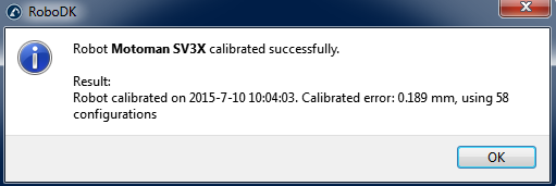
Close the window when the measurements are completed. The robot will be calibrated automatically and it will display the following message if there are no issues.
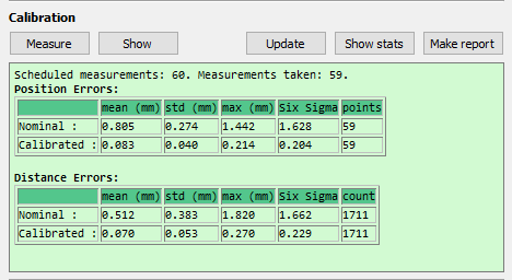
Finally, the green screen will display some statistics regarding the calibration measurements and how much the accuracy is improved for those measurements.
Validation
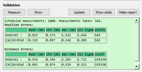
You shouldn’t validate the accuracy of the robot using the same measurements that you used to calibrate the robot, therefore, it is recommended to take additional measurements to validate the accuracy (having a more objective point of view of the accuracy results).
The same calibration procedure must be followed to take the validation measurements. The summary will display the validation statistics. See the following Results Section for more information.