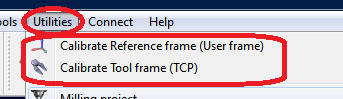
Tool calibration
Select Utilities➔Calibrate tool to calibrate the TCP using RoboDK. You can use as many points as desired, using different orientations. More points and larger orientation changes are better as you will get a better estimate of the TCP as well as a good estimate of the TCP error.
The following two options are available to calibrate a TCP:
●By touching one stationary point with the TCP with different orientations.
●By touching a plane with the TCP (like a touch probe).
It is recommended to calibrate by touching a plane reference if we have to calibrate a touch probe or a spindle. This method is more stable against user errors.
If the TCP is spherical, the center of the sphere is calculated as the new TCP (it is not necessary to provide the sphere diameter).
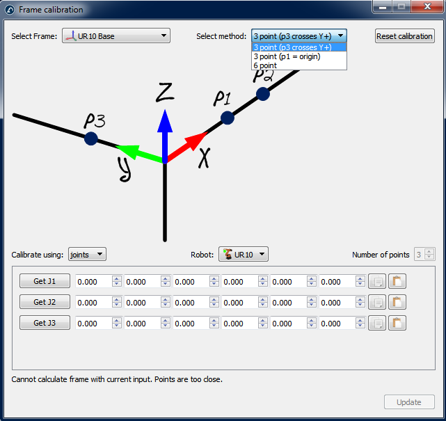
The following steps must be followed to calibrate the TCP with a plane (as seen in the picture):
1.Select the tool that needs to be calibrated.
2.Select the calibration method➔”Calib XYZ by plane”.
3.Select calibrate using “joints”.
4.Select the robot that is being used.
5.Select the number of configurations that you will use for TCP calibration (it is recommended to take 8 configurations or more).
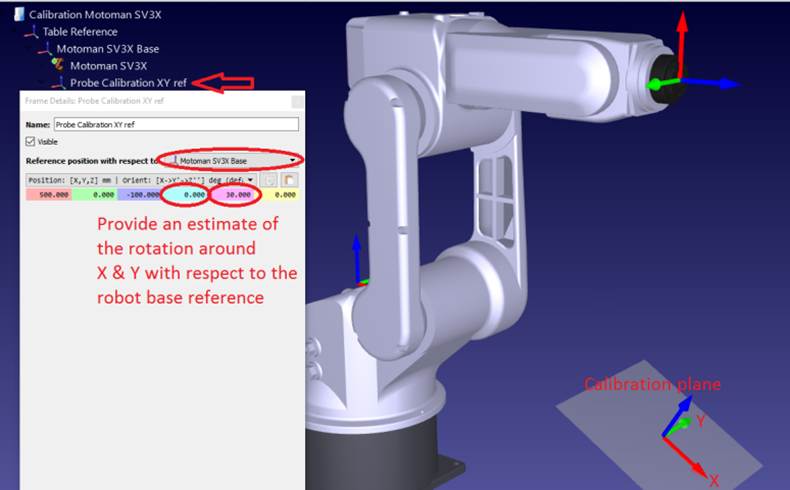
6.Select an estimate of the reference plane. If the reference plane is not parallel to the robot XY plane (from the robot reference) you must add an estimate of this reference plane within ±20 degrees. The position of this plane is not important, only the orientation.
7.You can start filling the table of joint values. You can fill it manually or by doing copy/paste with the buttons (as shown in the image). You can also use the button “Get Jx” to get the current joint values from the robot in the simulator. If you are getting the joints from a real robot connected to the robot you must first select “Get current joints” from the robot connection menu (see image attached or the appendix for more information about connecting a robot with RoboDK). It is strongly recommended to keep a separate copy of the joints used for calibration (such as a text file, for example).
8.Once the table is filled you will see the new TCP values (X,Y,Z) as the “Calibrated TCP”, towards the end of the window. You can select “Update” and the new TCP will be updated in the RoboDK station. The orientation of the probe cannot be found using this method.
9.You can select “Show errors” and you will see the error of every configuration with respect to the calculated TCP (which is the average of all the configurations). You can delete one configuration if it has a larger error than the others.
10.You must manually update the values in the real robot controller (X,Y,Z only). If this TCP will be used in a program generated by RoboDK, it is not necessary to update the values in the robot controller.