Robot Machining project
Follow these steps to set up a new robot machining project in RoboDK given an NC file generated using CAM software (such as G-code or APT):
1.Select Utilities➔
A new window will pop up, as shown in the image.
2.Select Select NC file in the Path input section
3.Provide an NC file, such as the following APT machining file:
C:/RoboDK/Library/Example-02.e-Robot Machining Chess Rook.apt
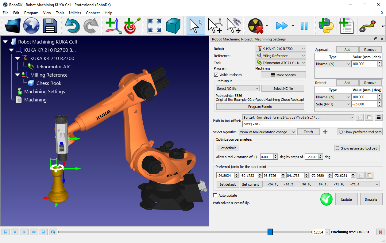
4.Rename the robot machining project to Machining Settings by right clicking the new item in the tree and selecting Rename (F2).
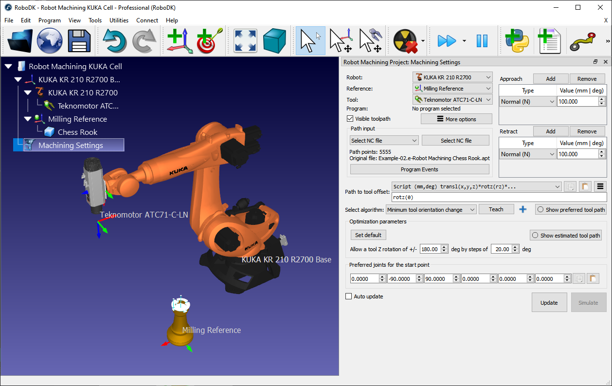
Select the robot, the reference frame and the tool in the top left section of the menu, as shown in the following image. The toolpath should be displayed in green with respect to the correct coordinate system.
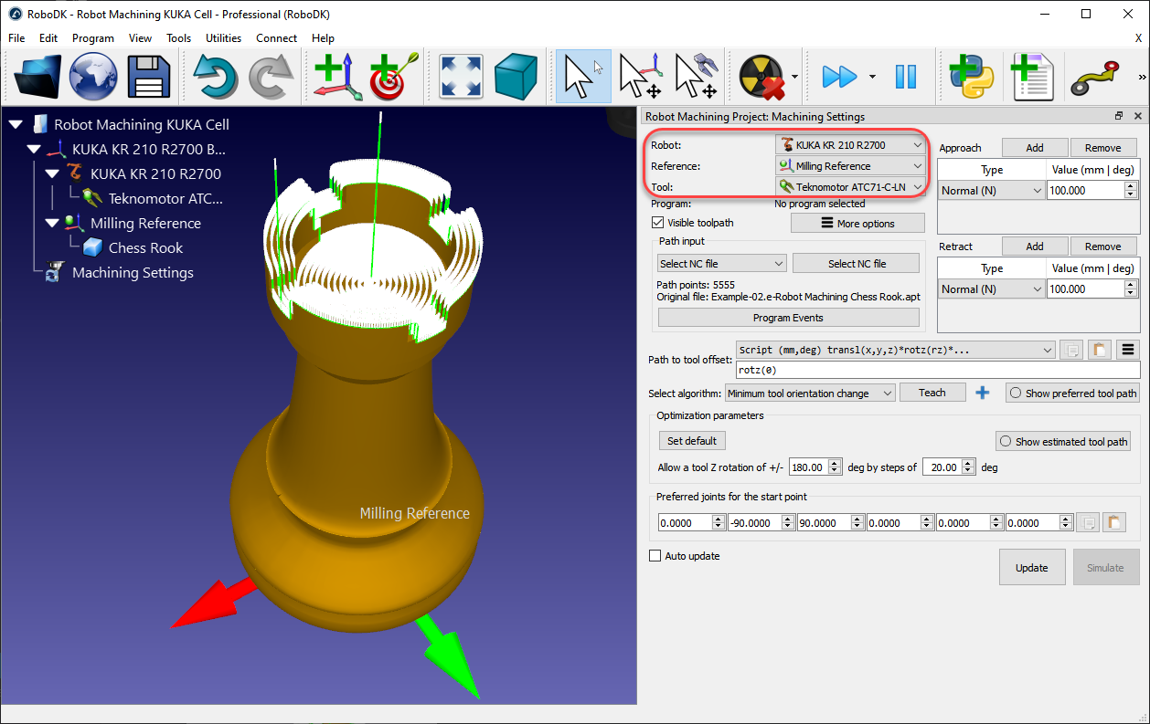
The machining toolpath is displayed in Green and the path normals are shown in white vectors. Uncheck Visible toolpath to hide the toolpath.
You can select Update to see if you can create a robot machining program with the default settings. If the program was generated successfully, you’ll see a green check mark. You can then select Simulate or double click the generated program to see the simulation start.
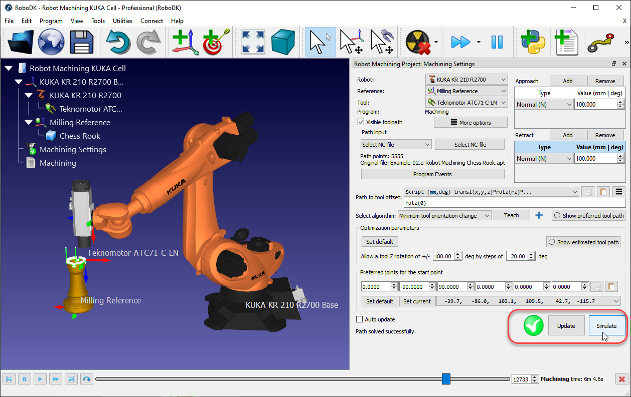
If you see a red cross with a warning message it means that your robot machining program is not feasible. You may have to change some settings such as the tool orientation, the optimization parameters, the start point or the location of the part.
The following sections provide more information about how to customize the robot machining settings.
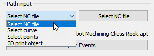
Path input
The path input allows you to select different ways to provide a toolpath.
●Select NC file: As one NC file (obtained from CAM software), as described in this section.
●Select curve: As one or more curves, as described in the Curve Follow Project Section.
It is possible to import curves as a list of coordinates in RoboDK.
●Select points: One or more points, as described in the Point Follow Project Section.
It is possible to import points as a list of coordinates in RoboDK.
●3D print object: As an object for 3D printing. A slicer is used to convert the geometry to a toolpath
Program Events
Select Program Events to display special events that need to be taken into account when generating robot programs. This includes triggering a tool change, setting the spindle speed in RPM or triggering specific programs on program start or program finish.
You can specify a rounding valuein Program events. This will automatically create a rounding instruction at the beginning of your program and will help making the robot machining programs smoother, preventing the robot to shake. For example, on an ABB robot this will set the ZoneData value in mm, on a Fanuc robot this will set the CNT value as a percentage and on Universal Robots controllers it will set the blending value in mm.
If you are using G-code or NCI files, custom M codes will be triggered by default as function calls to M_RunCode (the M code is passed as a parameter). You can remove the custom M calls by deleting the call to M_RunCode.
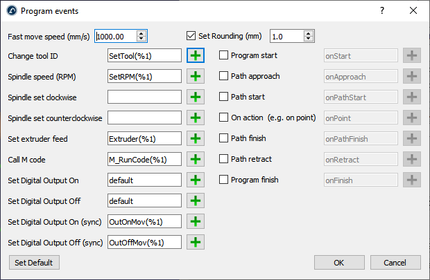
Move your mouse cursor over the corresponding field for more information to customize each section.
For example, when changing the tool you can use the %1 value to represent the tool ID provided by your CAM software. If you prefer triggering static functions instead of passing arguments you can replace SetTool(%1) by SetTool%1. When using tool 2, this would generate SetTool2 instead of SetTool(2).
Approach/Retract
You can customize your approach and retract movements from the top right of the robot machining menu. By default, RoboDK adds approach and retract movements of 100 mm along the normal.
Select Add to add an additional retract movement. The green path will be updated accordingly. It is possible to select among moving along a specific axis, provide coordinates, having an arc approach, etc. You can also combine multiple approach/retract movements by selecting the Add button.
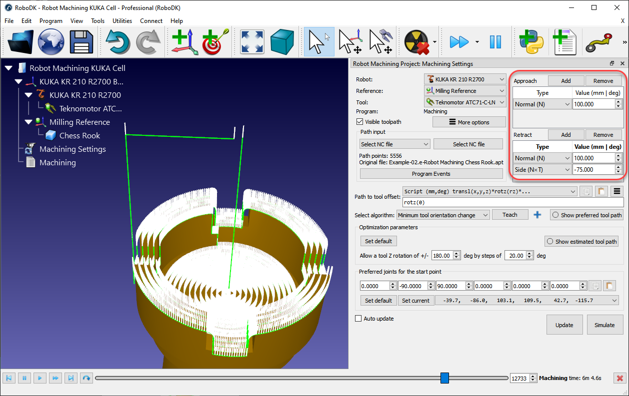
Select Remove to remove a specific approach or retract movement.
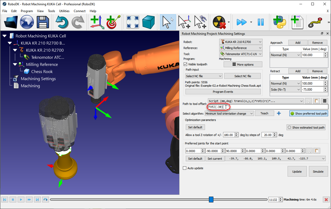
Path to tool offset
The path to tool offset allows changing the preferred orientation of the tool along the toolpath. This option is mainly used to turn the tool around the Z axis of the TCP. This allows handling the 6th degree of freedom around the tool axis. Several options are offered depending on the application and its requirements. For example, you can choose to minimize the tool orientation or follow the tool orientation along the path.
Since a 6-axis robot is used to follow a 3-axis or 5-axis CNC manufacturing program we have an additional degree of freedom to define. This degree of freedom is usually the rotation around the Z axis of the TCP. This additional degree of freedom is especially useful to avoid singularities, joint limits, collisions or reachability issues.
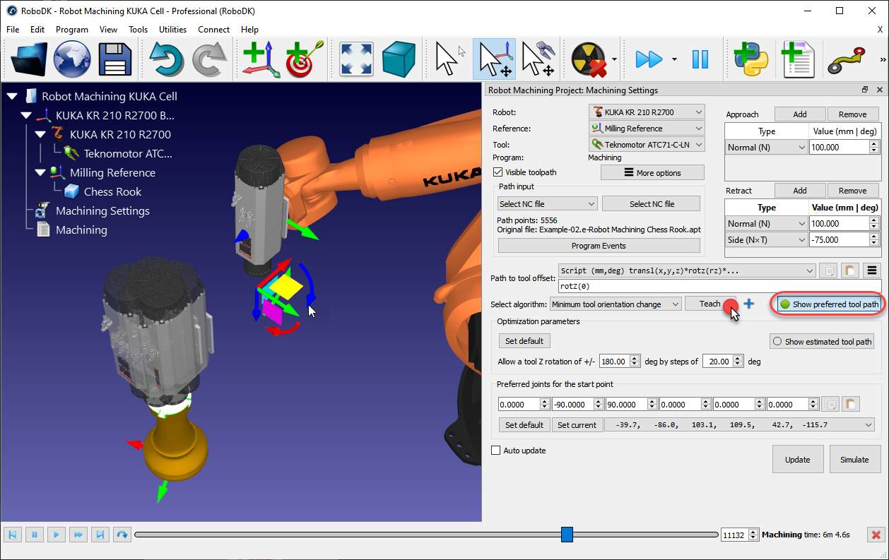
By default, the path to tool offset displays a rotz(0) transformation. This means you can add an additional rotation around the Z axis of the tool. This value can be modified to establish the preferred orientation of the tool, modifying the orientation around the Z axis of the TCP or in combination with other axes. The preferred orientation is the orientation the robot will try to keep while following the toolpath.
By default, RoboDK uses the Minimum tool orientation change algorithm. This means the orientation of the tool is kept as constant as possible along the toolpath. In general, this option is suitable for milling operations as it minimizes robot joint movements. Alternatively, other algorithms/methods are available, such as the tool orientation following the toolpath (useful for cutting applications, where the blade needs to remain tangent along the path), or the robot holding the object if the toolpath needs to be followed attached to the robot tool (for example, for dispensing or polishing applications, also known as Remote TCP configurations).
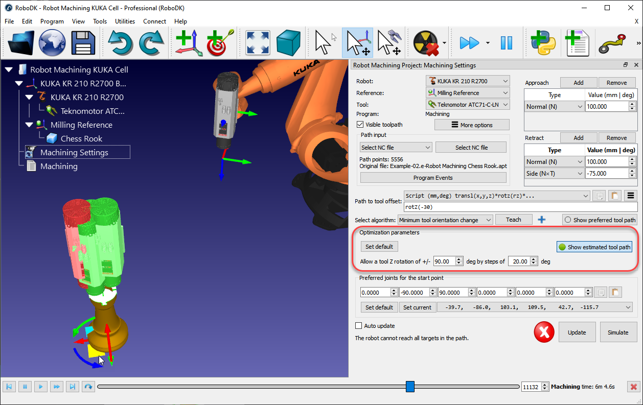
Optimization parameters
Given a preferred tool orientation, the robot can have a certain freedom to turn around the Z axis of the tool. This allows the robot to solve the program avoiding robot singularities, joint limits and making sure all points are reachable. By default, RoboDK allows the tool to rotate up to +/-180 degrees around the TCP axis by increments of 20 deg.
It is recommended to constrain this rotation depending on the application. For example, it is possible to enter +/-90 degrees to constrain the allowed rotation by half. Decreasing this parameter will also reduce the processing time to obtain the program.
If some points of the path are not reachable, it is recommended to rotate the reference frame or to be more permissive with the tool Z rotation. The reference frame can be moved by holding the Alt key and dragging the coordinate system to better fit the part inside the robot workspace.
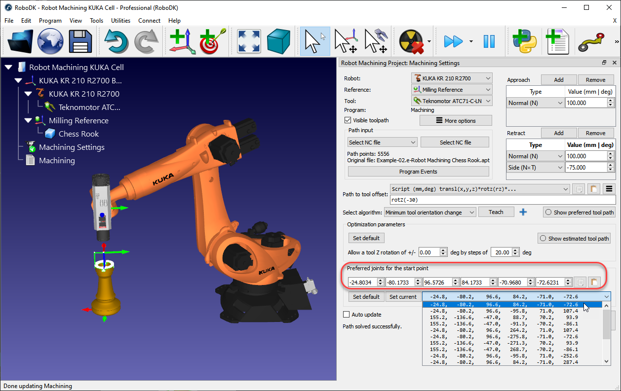
Preferred Configuration
RoboDK automatically selects the start configuration that is closer to the preferred start joints (Preferred joints for the start point). From that point, the robot will follow linear movements, so the robot configuration will not change.
A dropdown menu will display all the possible solutions to start the program. If required, select a preferred robot joint configuration, and select Update to recalculate the program.
Update program
Select Update to generate the robot program given the provided settings. A green check mark is displayed if the program can be successfully created. You’ll then see a new program in the station called Machining.
Double click the generated 
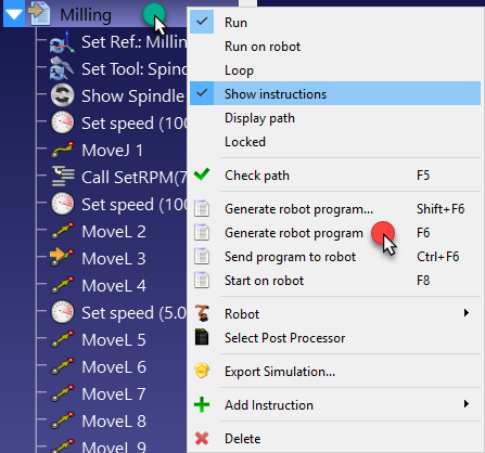
Right click the program and select Generate robot program (F6) to generate the robot program. More information about program generation in the Program section.