Offline Preparation
A robot program must be prepared to complete the ballbar test. The robot program is a circular path around a center point. This section explains how to prepare the program. Before continuing, it is recommended to watch the following introductory video: https://robodk.com/ballbar-test.
What’s required from the robot cell:
1.The joints of the robot when setting the pivot support (center of the circle).
2.The [X, Y, Z] values of the TCP of the tool (tool position relative to the robot flange). These values are very important if we want to make a validation tool together with the validation of the robot. Otherwise, this information is not important (an estimate is sufficient) because the accuracy of the TCP will not be required or validated with the ballbar test.
Create a RoboDK station
You should follow these steps to prepare the ballbar test offline:
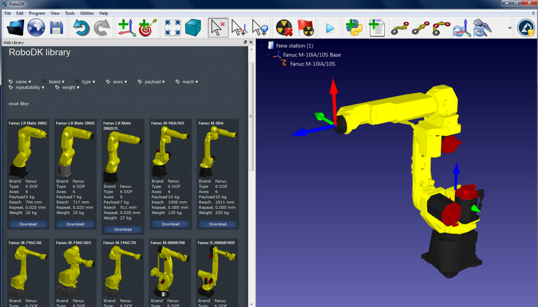
1.Select the Robot:
a.Select File➔Open online library. A window should appear with a list of robots.
b.(Optional) Use filters to refine the selection of the robot.
c.Find your robot and select Download.
Alternatively, select File➔Open… and select a robot file in the computer. This file can be downloaded from the website: https://robodk.com/library or obtained after a robot calibration project.
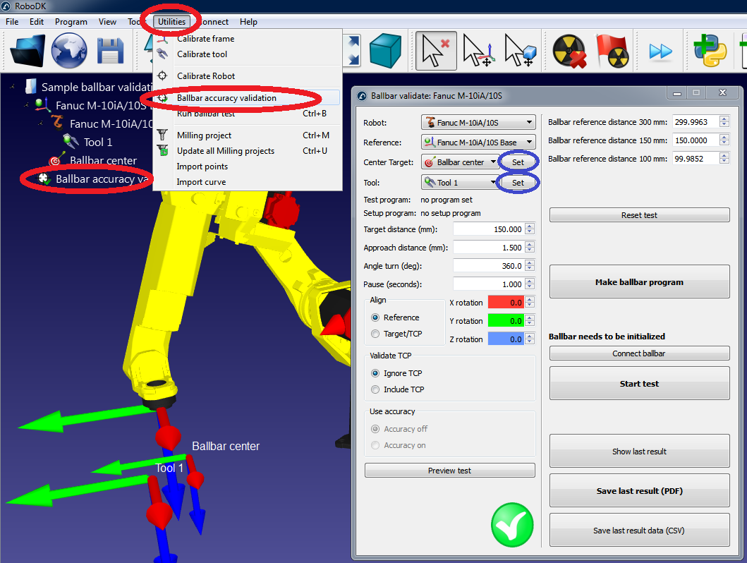
2.Add the ballbar test module in the station:
a.Select Utilities➔Ballbar accuracy test
b.The following window will appear and a target Ballbar center will be created automatically. If the robot has no TCP, the TCP Tool 1 will also be created automatically.
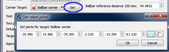
3.Insert the robot joints of the center of the ballbar test (target Ballbar center):
a.Select Set next to the target Ballbar center.
b.Enter the robot joints (joint axes 1 to 6).
c.Select OK.
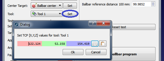
4.Enter the TCP coordinates:
a.Select Set next to the selected tool (Tool 1 in this example)
b.Enter the X,Y,Z coordinates of the TCP (relative to the robot end effector)
c.Select OK
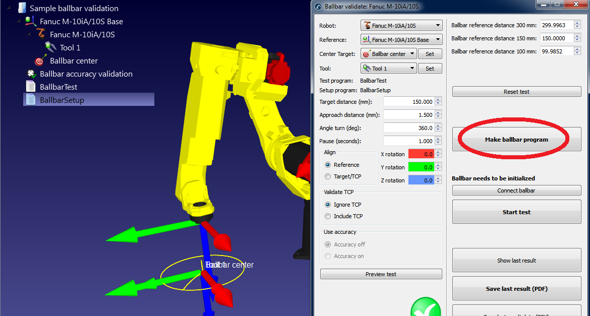
5.Generate programs:
a.Select Make ballbar program and the program will be created. Actually, two programs will appear:
i.BallbarSetup: This program is used to place the center toolcup pivot point (center of the circle) in the same place it was previously positioned
ii.BallbarTest: This program is used to make the circle around the pivot point (center of the circle) for data acquisition with the ballbar
b.Double click the newly generated programs. RoboDK will simulate the robot running the programs.
If the ballbar test is not feasible with the default settings you can change the test parameters. See the next section on how to change these settings.
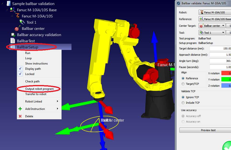
6.Once the robot program is to your liking, the program files for the robot can be generated:
a.Right click on the BallbarTest program.
b.Select Generate robot program
c.Repeat for the BallbarSetup program (all programs can be automatically generated on the desktop by pressing F6).
d.Then the programs can be saved in a USB disk and transferred to the robot. FTP connection can also be used with most robots.
7.Finally, select File➔Save Station to save the RoboDK station in a single file. The project can be resumed in RoboDK by double clicking the file (rdk format).
Editing the ballbar test parameters
The following screen can be seen in the ballbar test parameters menu. It can be accessed by double clicking the item Ballbar accuracy validation in the station (see previous step).
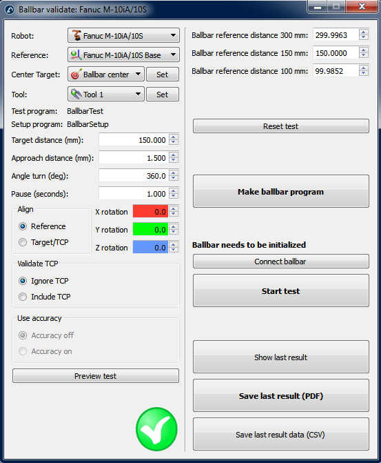
It could be that the ballbar test is not feasible by default. The feasibility of the test depends on all these parameters plus the robot joints of the center toolcup and the position of the TCP.
If the test is not feasible in the first place, we can select “Preview test” and we will probably see an incomplete sequence. In this case, we can decrease the “Angle turn (deg)”) so that the program is feasible. If this is not the case, we can reduce the radius of the circle (“Target distance”). With the Renishaw QC20-W ballbar, we can test distances of 100 mm, 150 mm and 300 mm with an error of +/-1 mm. With the Renishaw RCS L-90, the range of the ballbar is 240 mm to 330 mm. The “Approach distance (mm)” and the pause (“Pause (seconds)”) can be left as default. These parameters allow detecting the start and the end of the test.
The test plane is oriented with respect to the robot base reference frame (“Reference” in the “Align” section), this means that the XY plane of the robot reference frame is used to create the circle. We can choose to make the test with respect to the tool reference frame. In this case, the XY plane of the tool is used (when the center was taught). We can add additional rotations with respect to X, Y and/or Z axis of the reference frame in both cases.
If we change certain parameters (such as adding the tool in the validation), the message “Important: The TCP must be accurate” will appear. This means that the movements are calculated with respect to the tool center. Otherwise, we can have TCP errors and the test will be feasible anyway.
If we select the option “Include TCP” the tool orientation changes with the movement along the circle. This option allows evaluating the error of the robot plus the tool as one system. Otherwise, we are checking the error of the robot only (“Ignore TCP”).