Results
Once the path accuracy test is completed it is possible to obtain a PDF report by selecting Make PDF report, from the Path validation window. This will generate a PDF with some statistics and graphics about the path accuracy, speed and acceleration.
The results of the sample test prepared in the previous sections are shown in the following images. In this example, the ISO9283 program was run in two different modes:
●Manual mode at 75 mm/s speed
●Automatic mode at 300 mm/s speed
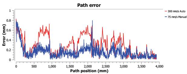
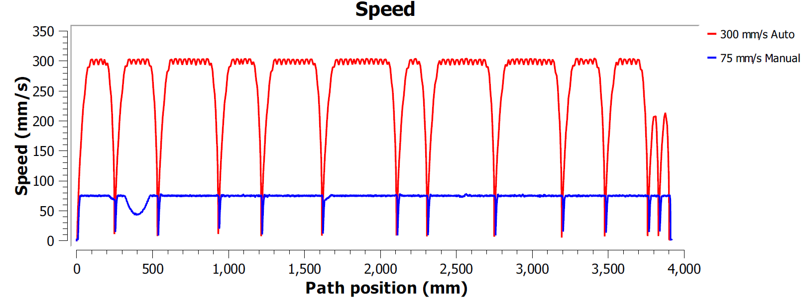
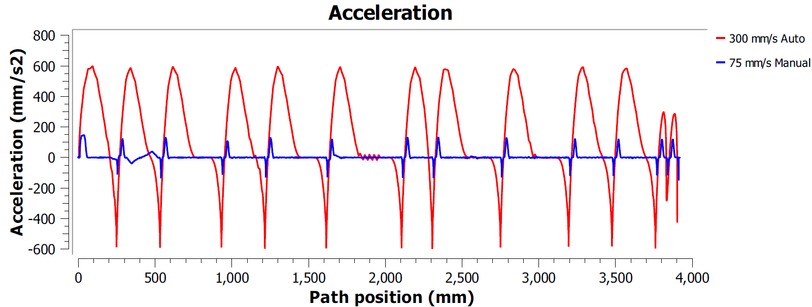
In this example, both programs were generated using the Fine accuracy option. This means that the robot will stop at every point to make the path as accurate as possible. In this case, it is typical to observe high accelerations and decelerations along the path because the speed must be zero at the end of every line or circle movement (corners).
Most robot brands offer rounding options to avoid this effect by smoothing the edges. For example, ABB calls it ZoneData and allows specifying a zone of accuracy where the controller is allowed to smooth the edges, Fanuc calls it CNT and allows specifying a percentage of smoothing proportional to the speed, KUKA option offers the $ADVANCE instruction with the C_DIS flag and Universal Robots allows specifying a blend radius to smooth the edges).
Therefore, the path accuracy test allows finding a good compromise between keeping a smooth speed while maintaining acceptable accuracy levels close to the path edges.
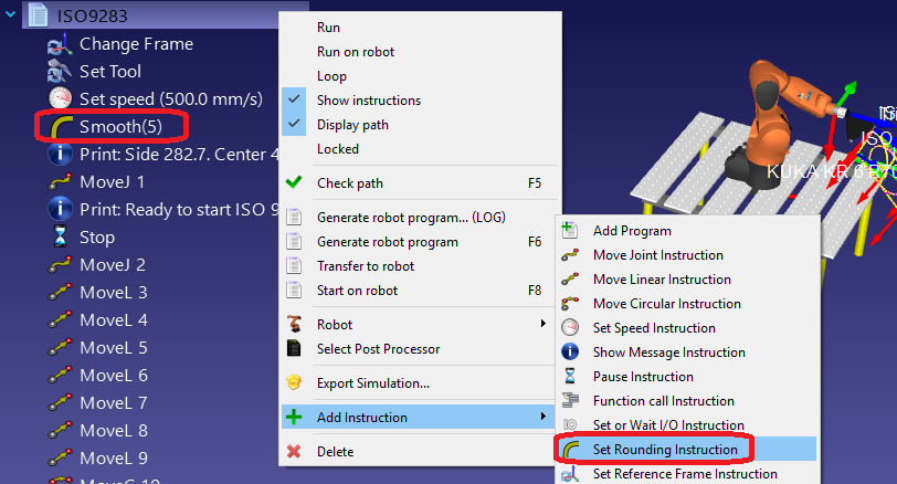
It is possible to specify the rounding parameter in RoboDK as well as the program speed. To edit a program for such a test:
1.Right click the program
2.Select Show Instructions
3.Select the first or second instruction
4.Select Program➔Set Rounding Instruction to specify a rounding accuracy
5.Select Program➔Set Speed Instruction to specify the speed