Welding Add-In
The RoboDK Welding Add-In allows you to apply different welding instructions and recipes with RoboDK programs and properly visualize them.
With the RoboDK Welding Add-In, you can do the following:
1.Easily create and add commands, such as weld start, continue and end commands
2.Define a list of parameters for the created commands (specific to welding and visualization)
3.Visualize the trajectory as a solid model
4.Visualize weld creation (material addition) using a predefined weld shape/profile
5.Easily create and add custom Insert Code instructions
6.Save all created data in the station project
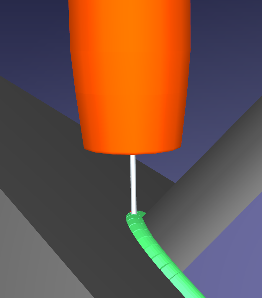
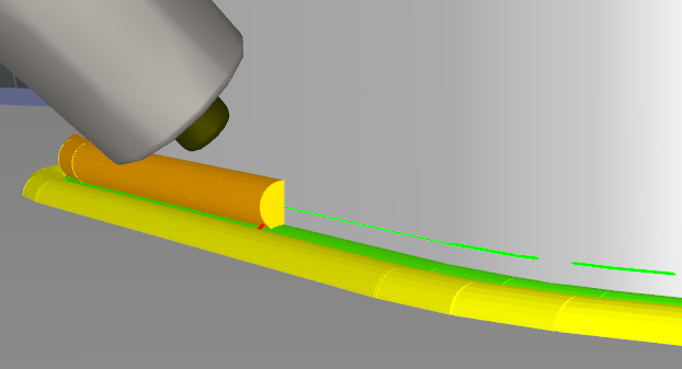
The following image shows a preview of the welding trace.
How To Install
You can find more information about the Welding Add-Inin our library of Add-ins: RoboDK Addins Library.
You may need to send a request to obtain the welding Add-in. Installation is automatic using the Add-in Manager once you have the RDKP Add-in package.
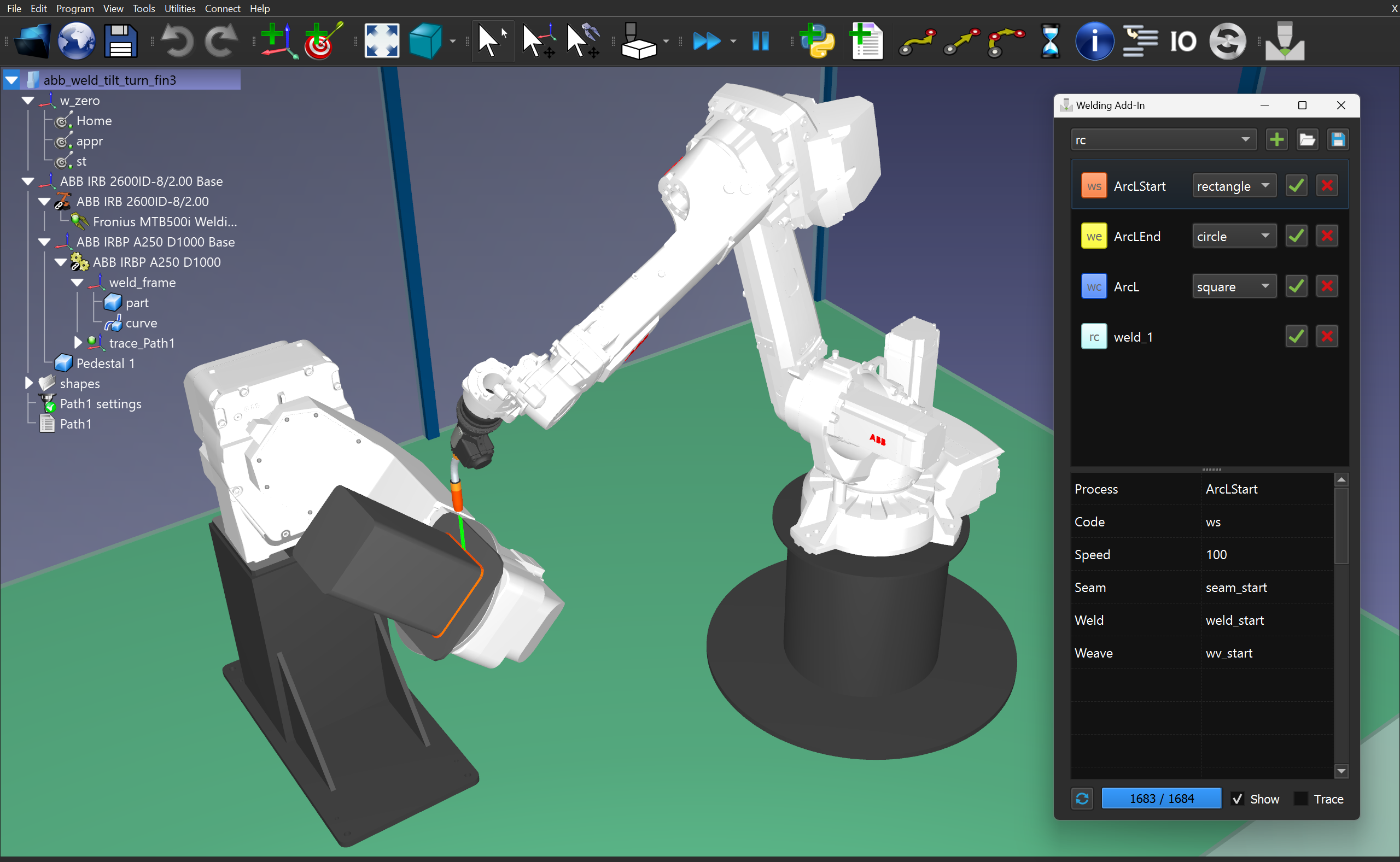
Welding Interface
This section covers the available functionalities of the user interface of the welding Add-in.
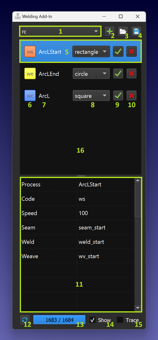
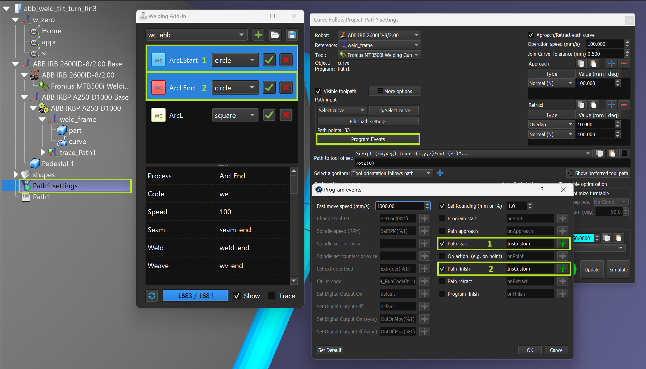
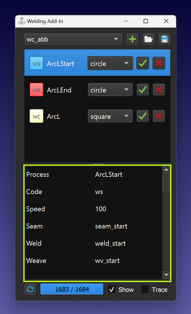
The Welding Add-In contains the following functional elements:
1.Instruction selection pull-down menu.
2.Instruction adding to the instructions list.
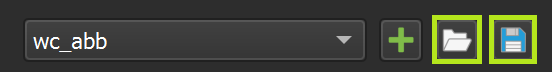
3.Import instructions list.
4.Export instructions list.
5.Current instruction (selected).
6.Instruction code and icon color (click to change color).
7.Instruction name (unique).
8.Appropriate path shape.
9.Add instructions to the program sequence or CFP.
10.Delete instructions from the list.
11.Parameters linked to the selected instructions.
12.Build a path model.
13.Path model building progress.
14.Path model visibility flag.
15.Path trace flag (allows simulate material’s adding).
16.Instructions list area.
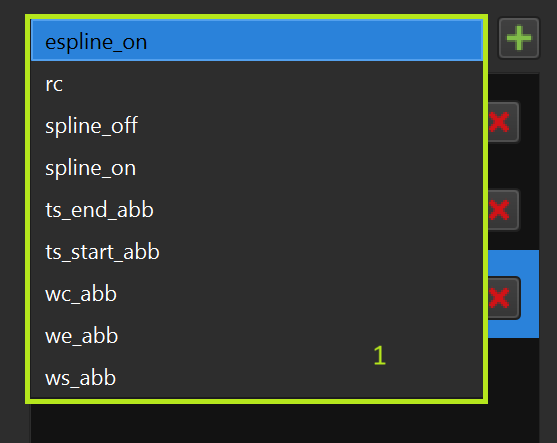
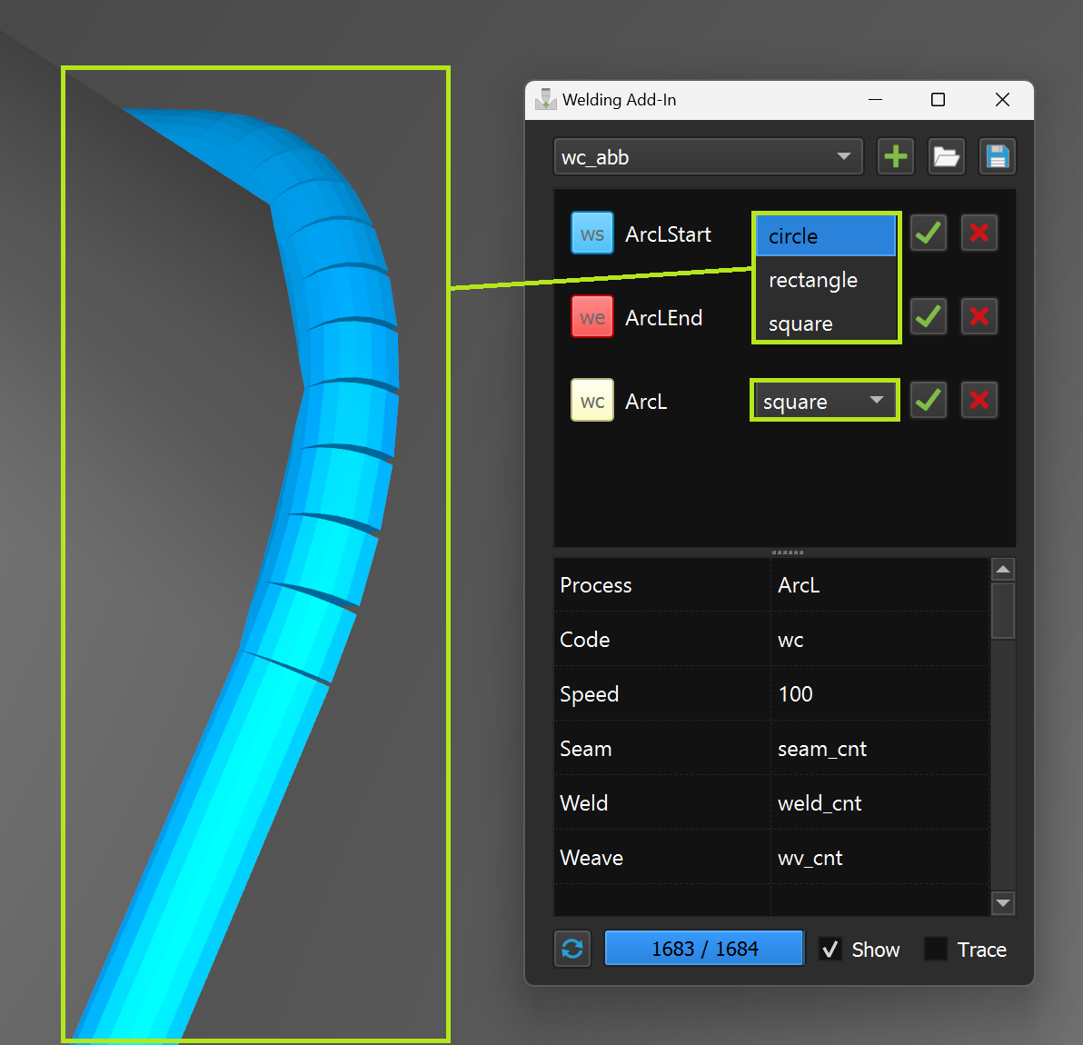
Instruction selection pull-down menu
You can select the instruction to be added from the pull-down menu:
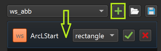
Adding an instruction to the instruction list
You can add the selected instruction from the pull-down menu using the '+' button:
The instruction templates are in the following folder (default RoboDK installation):
C:\RoboDK\Addins\com.robodk.app.welding\WeldingAddIn\templates
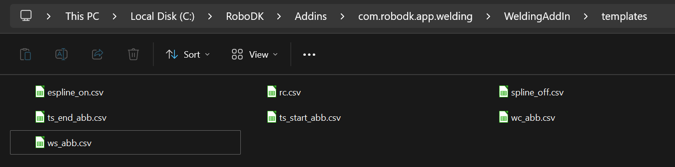
Templates are presented as regular '.csv' files with the string format 'parameter->value':
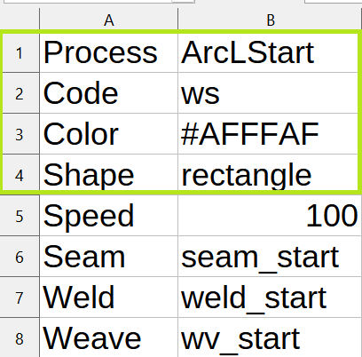
1.‘Process’ ➔ ‘Process name’ (some name should be specified)
2.‘Code’ ➔ ‘Instruction code’ (one of the supported instruction codes)
3.‘Color’ ➔ any color code in the hex format
4.‘Shape’ ➔ file name with the shape model for the welding instructions
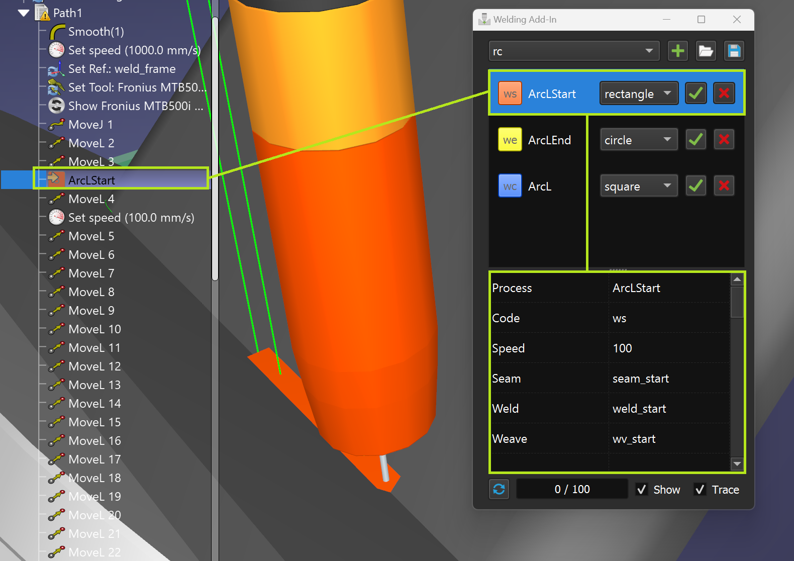
Current instruction (selected)
You can access the parameters by selecting a line in the instruction list (9). In addition, the instruction line is highlighted automatically during program execution or when the corresponding program instruction is double clicked:
Instruction code & icon color
You can set the color of the instruction and the corresponding path by clicking on the instruction code button (make sure that the instruction line is selected first):
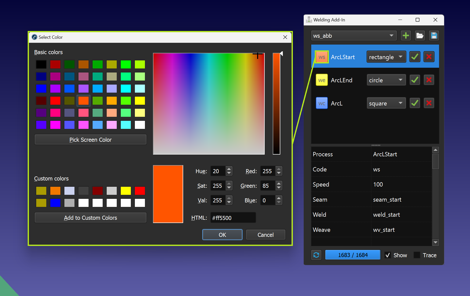
1.ws – welding start instruction
2.wc – welding continue instruction
3.we – welding end instruction
4.rc – custom Insert Code instruction
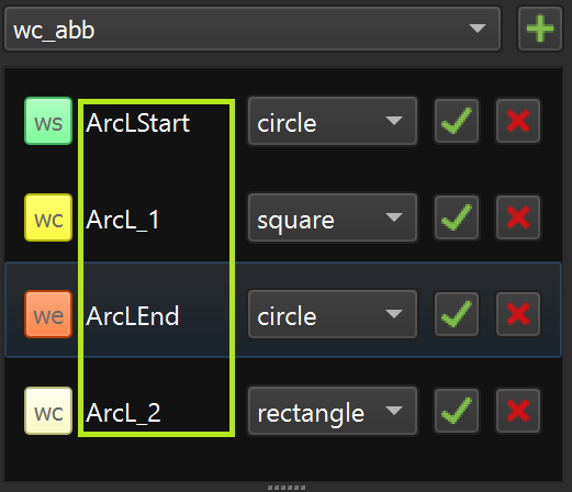
Instruction name
Every instruction in the instruction list should have a unique name (value of the 'Process' parameter):
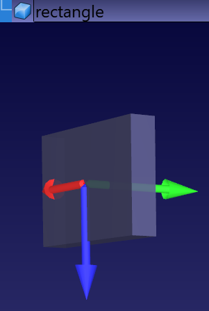
Path shape
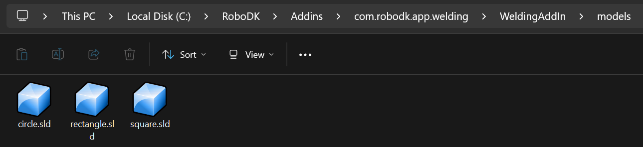
If the instruction template has a path shape definition, it can be selected from the pull-down menu:
C:\RoboDK\Addins\com.robodk.app.welding\WeldingAddIn\models
Add instructions to the program sequence
A single instruction or a pair of sequentially selected instructions can be added to a RoboDK program sequence.
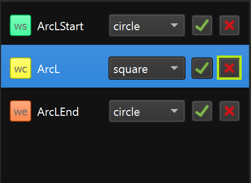
Delete instruction from the list
You can delete an instruction from the instruction list by clicking the “X” button.
Parameters
You can change parameters directly in the parameter table. The changes can be saved automatically.
Parameters import/export
You can import the entire list of instructions with parameters or export all data using the import/export functions.
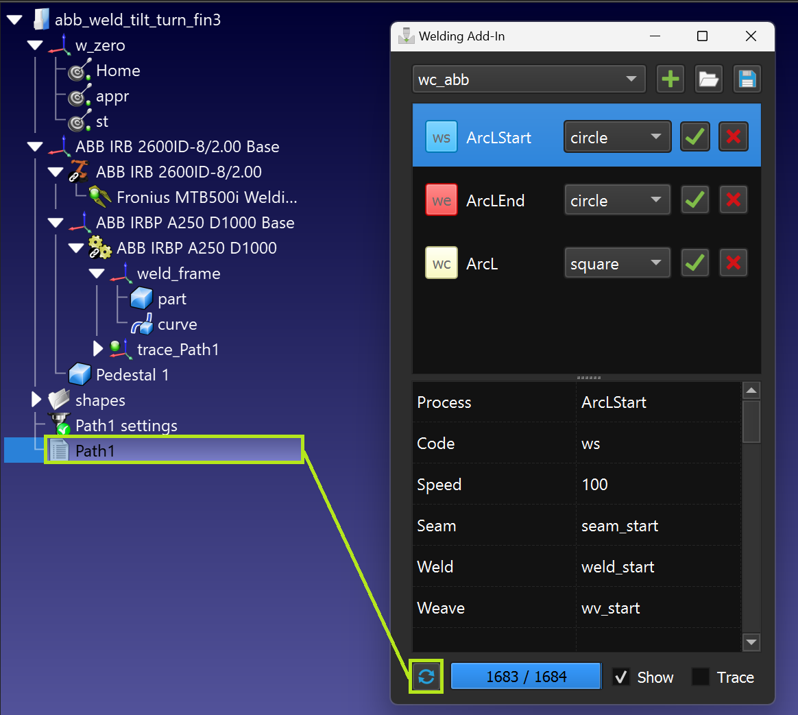
Path building
You can build the path using the 'Build' function for the selected program (it needs to contain welding instructions).
Path tracing
By enabling the "Trace" option, it is possible to see how the welding material is applied as the robot is moving along the welding path.

Supported post processors
The Welding Add-in offers simulation and off-line programming features. Instructions are added to the output program specific to your robot controller. An increasing number of post processor are supporting the Welding Add-in instructions, including:
1.ABB RAPID IRC5
2.ABB RAPID S4C
3.Fanuc R30i
4.Kawasaki
5.KUKA KRC2 DAT
6.Motoman
Please contact us to add support to a specific controller.
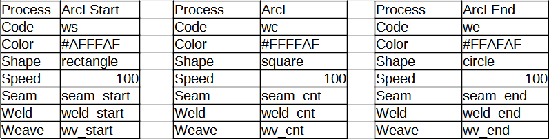
ABB welding templates
The templates abb_ws.csv, abb_wc.csv and abb_we.csv are used as ABB welding templates for weld start (ArcLStart), weld continue (ArcL) and weld end (ArcLEnd) commands respectively. The parameters 'Seem', 'Weld' and 'Weave' in these templates must be equal to the names of the corresponding welding variables on the real controller.
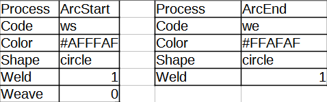
Fanuc welding templates
The fanuc_ws.csv and fanuc_we.csv templates are used as Fanuc welding templates for the ArcStart and ArcEnd commands respectively. ArcStart can be used again to change the welding mode directly in the process. The 'Weld' and 'Weave' parameters in these templates must be equal to the values of the corresponding welding variables on the actual controller.
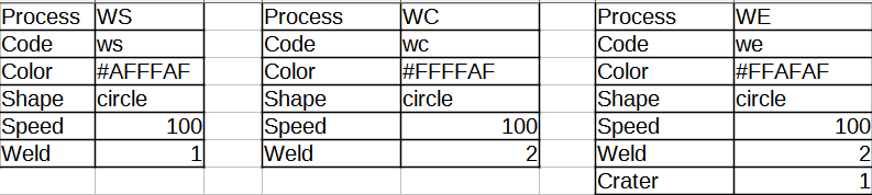
Kawasaki welding templates
The templates kawasaki_ws.csv, kawasaki_wc.csv and kawasaki_we.csv are used as Kawasaki welding templates for the weld start (WS), weld continue (WC) and weld end (WE) commands respectively. The 'Weld' and 'Crater' parameters in these templates must be equal to the corresponding weld variables on the actual controller (e.g. W1SET and W2SET numbers).
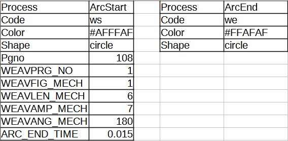
KUKA welding templates
The kuka_ws.csv and kuka_we.csv templates are used as KUKA welding templates for the ArcStart and ArcEnd commands respectively. The parameters in the ArcStart template must be equal to the values of the corresponding welding variables on the actual controller.
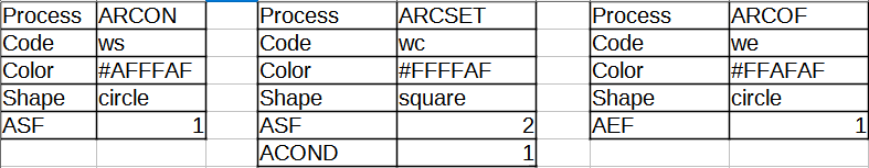
Motoman welding templates
The templates motoman_ws.csv, motoman_wc.csv and motoman_we.csv are used as Motoman welding templates for weld start (ARCON), weld continue (ARCSET) and weld end (ARCOF) commands respectively. The parameters 'ASF', 'ACOND' and 'AEF' in these templates must be equal to the values of the corresponding welding variables on the real controller.