Spot welding
Spot welding is one of the most common tasks that require using robot simulation software. This guide shows you how you can simulate and program a robot for automated spot-welding of car body panels.
You can find the sample available in our library of examples: Spot-welding station link.
Requirements
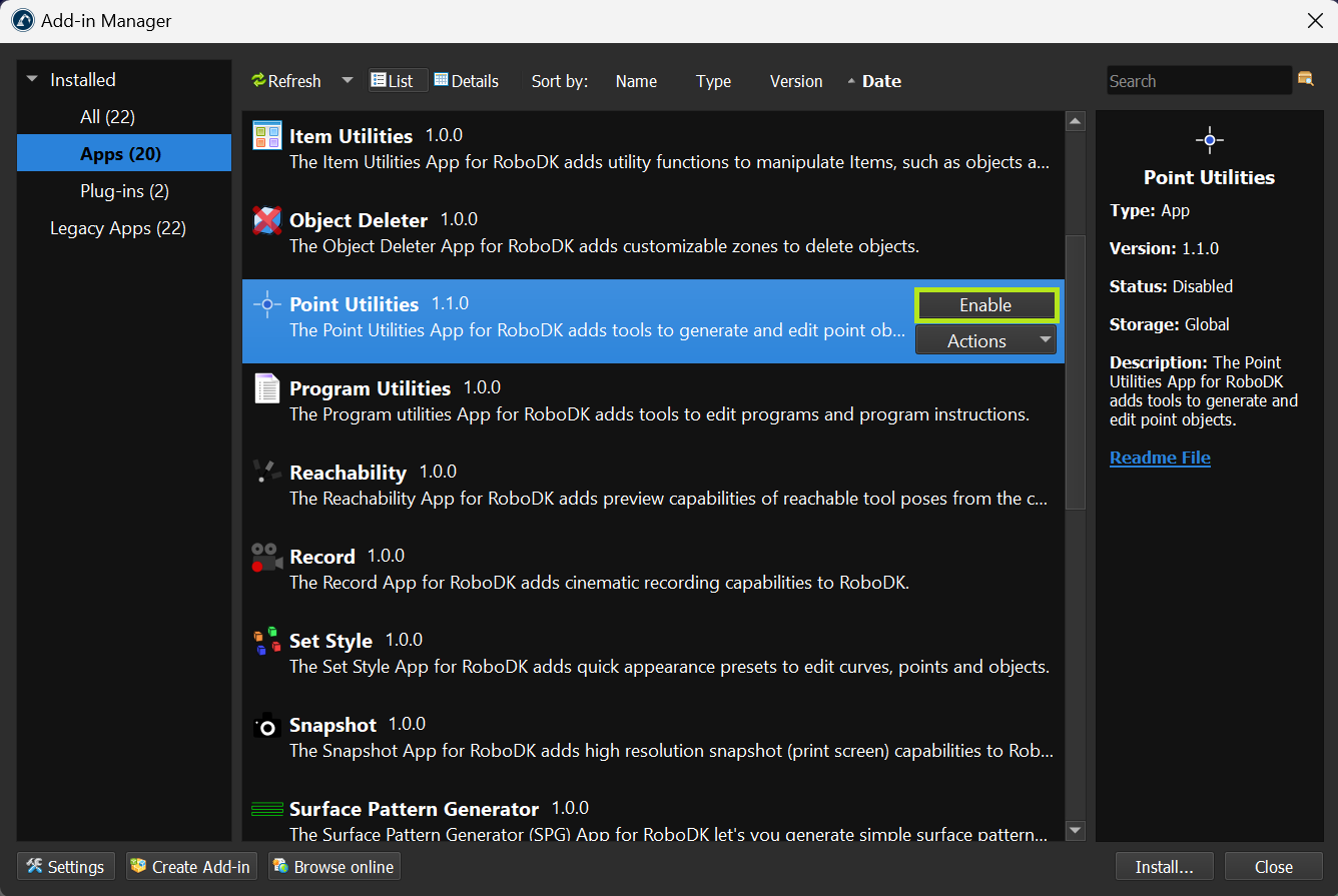
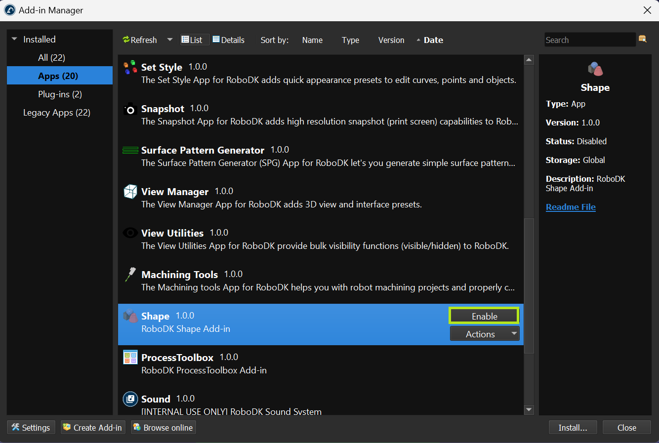
You should use RoboDK v5.5.4 or later to properly create the spot welding example. This version of RoboDK include the Point Utilities and Shape Add-In which facilitate the creation of the spot welding project.
Workflow
This section will guide you to create a spot welding simulation including the automatic generation of a collision-free path using the Collision Free Planner plugin.
This section breaks down the process of creating the spot welding project in the following steps:
1.Load all necessary models, robots, tools.
2.Setup the tool (TCP).
3.Create targets.
4.Create and check robot paths/trajectories.
5.Analyze the path.
6.Organize the program sequence.
7.Generate robot programs.
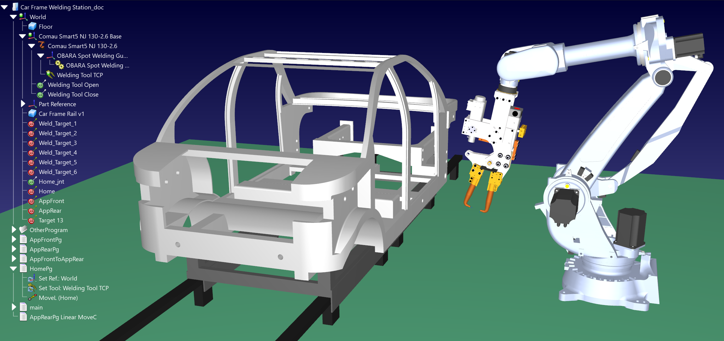
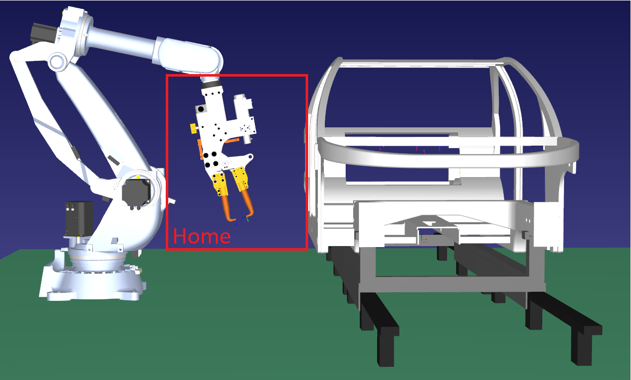
Station components
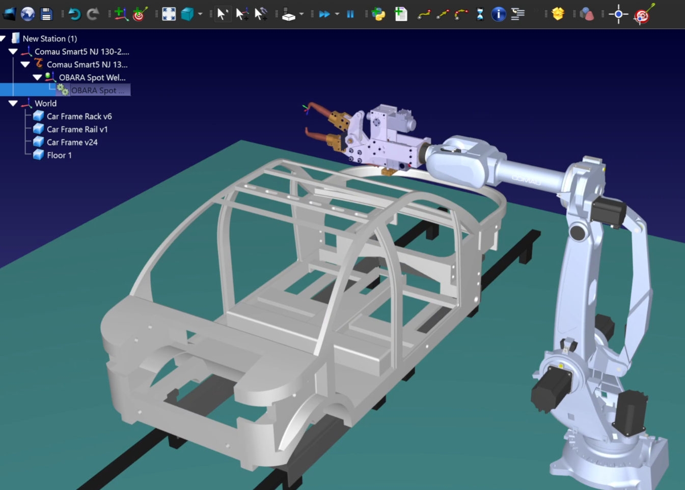
You should first load a robot and a spot welding gun as the robot tool.
You can use the following components from RoboDK online library:
1.Robot: Comau Smart5 NJ 130-2.6
2.Tool: OBARA Spot Welding Gun
The pedestal and fixture will be loaded using local files, and to create the floor, we will use the Shape Add-In. You can look at our Getting Started Guide and Shape Add-in Documentation for further details.
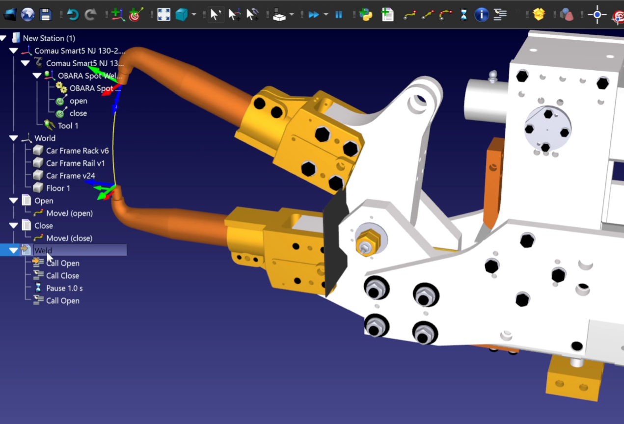
Spot Welding Gun
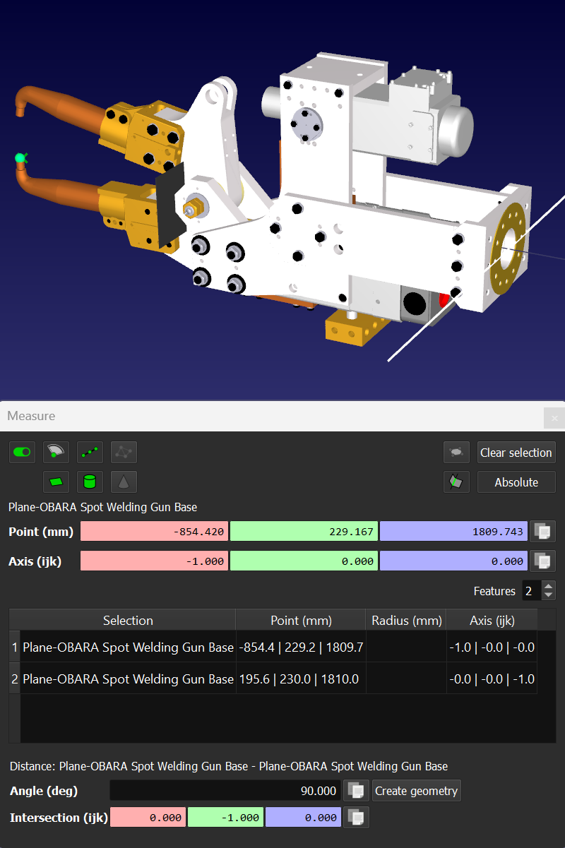
This section shows how you can animate the movement of the spot welding gun and create the tool center point (TCP).
To add a spot-welding gun with a movable clamping part, the corresponding TCP should be defined, and the mechanism should be attached separately. You can measure the position of the TCP point in relation to the flange by selecting Tools-Measure.
You can create two joint targets to open and close the spot welding gun. These targets can be used in programs to simulate the spot-welding process:
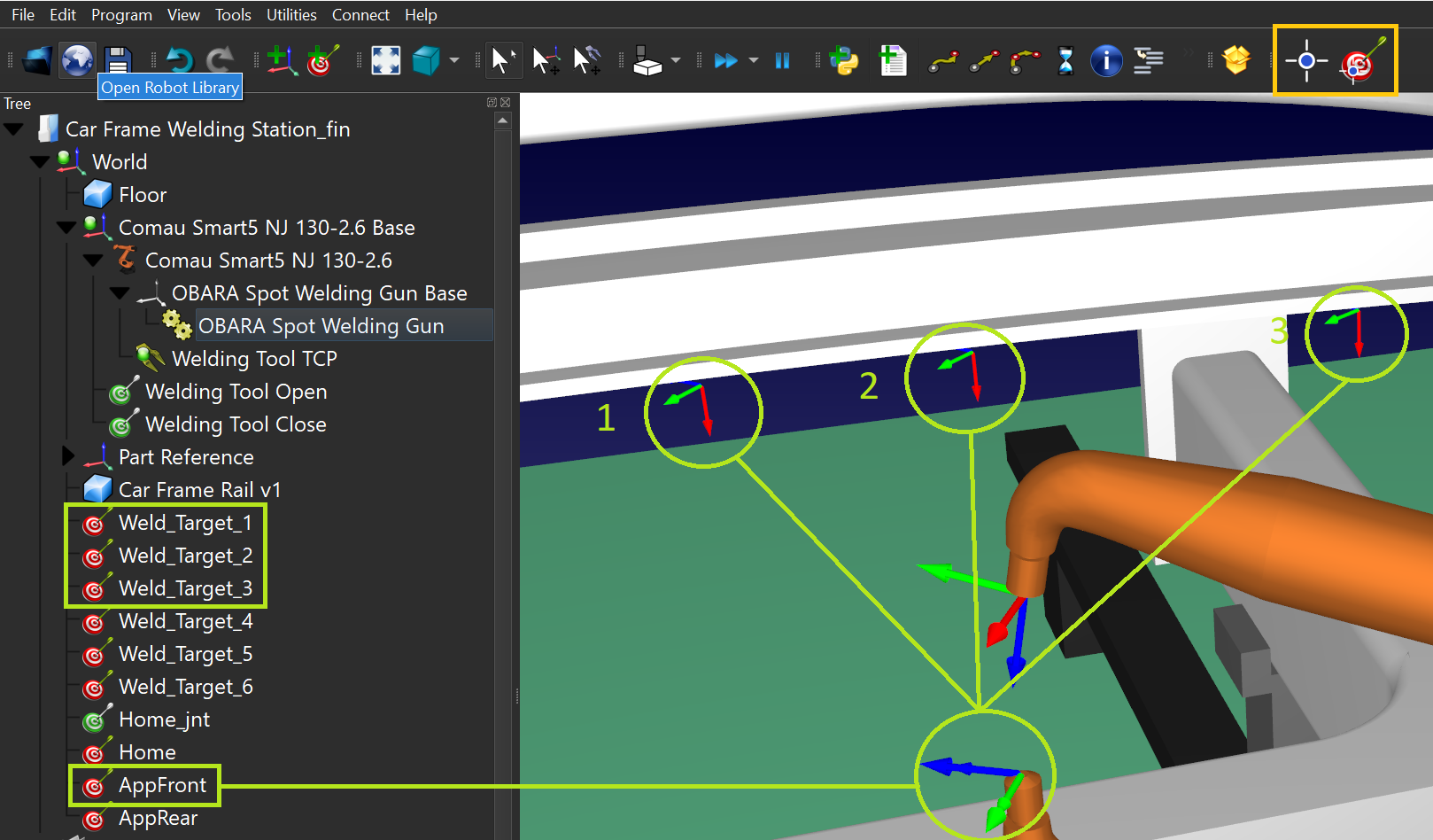
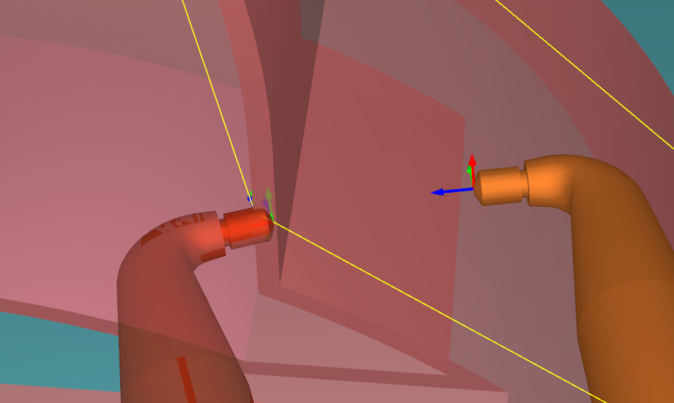
Spot Welding Points
This section shows how to create the spot welding points on the car frame to move the spot welding gun to.
Let's assume that you need to spot-weld the front and rear part of the car frame. Using the Point Utilities Add-in, you can place spot welding points directly on surfaces. After converting points to targets (this is a built-in feature of the Point Utilities add-in) you can realign the targets' orientation relative to the TCP angles:
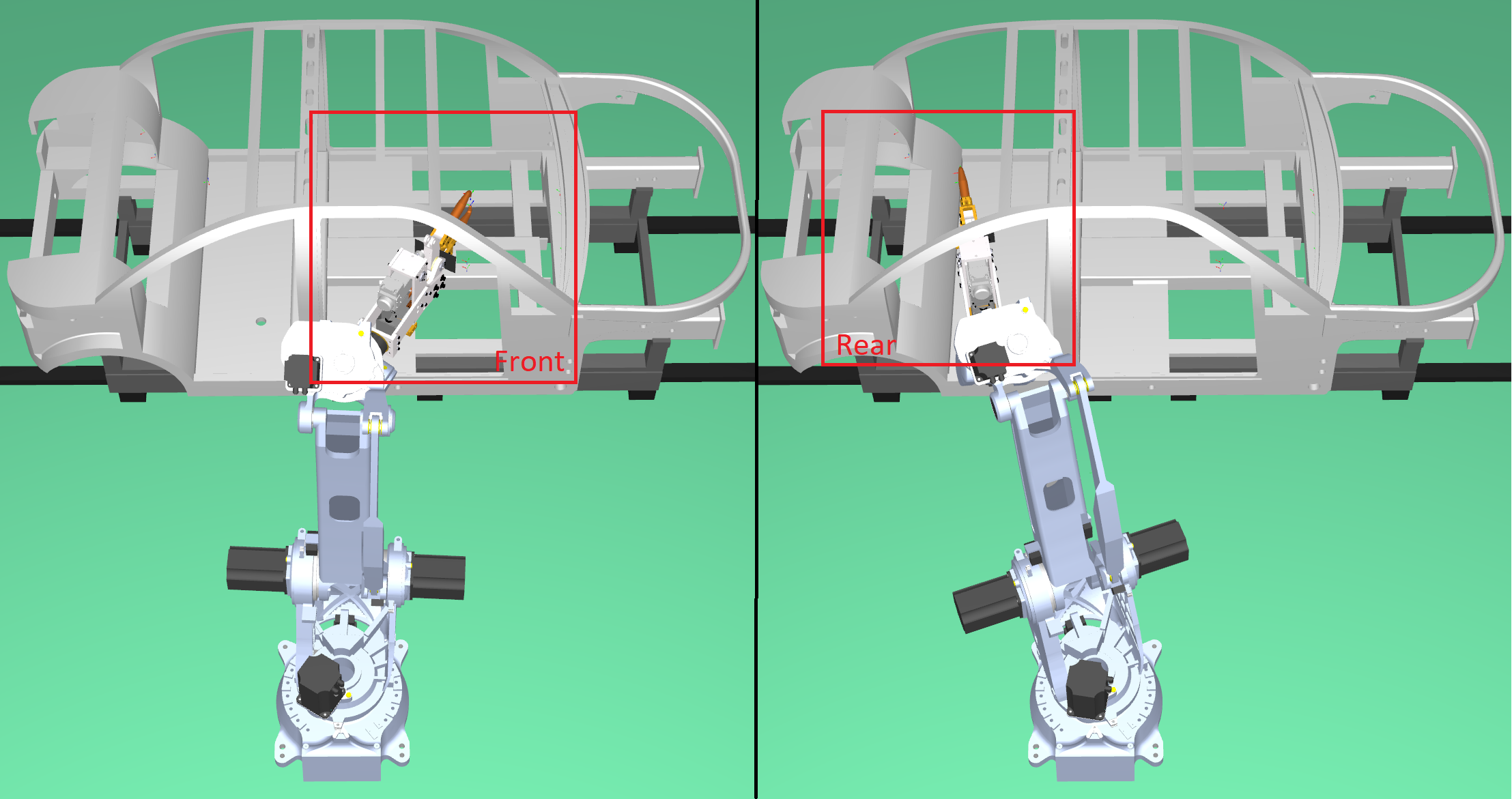
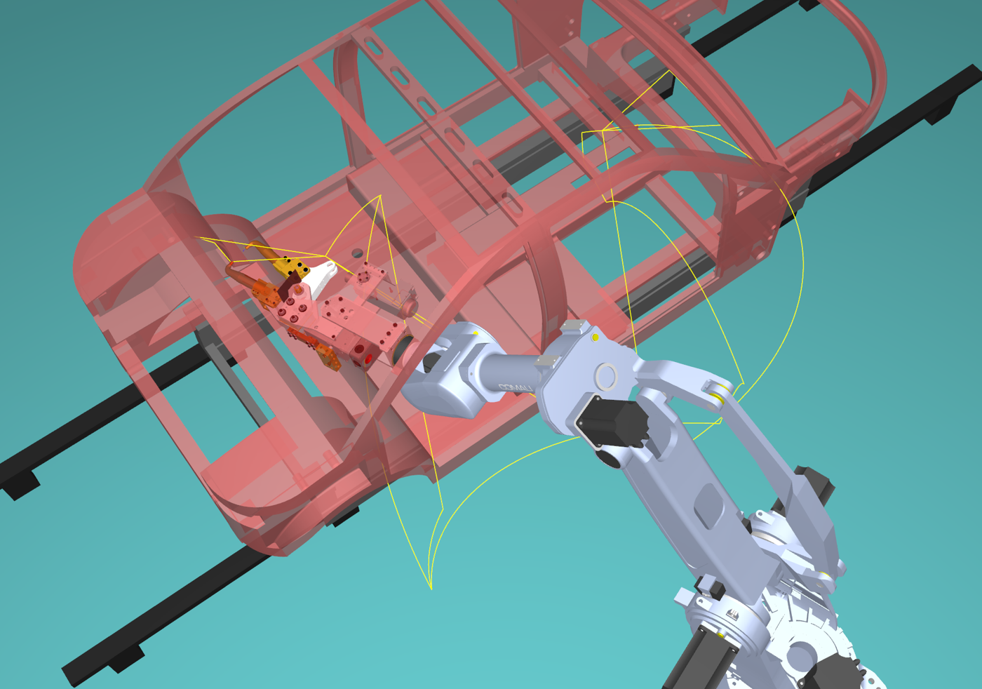
Trajectory planning
This section shows how you can create a collision-free path between 2 points inside the car frame.
The vehicle frame has a force beam that prevents easy access from the front to the rear, you need to create two approach targets that allow passing inside the frame.
We also need to create an intermediate target between the two approach targets. We can create approach targets based on the tool position for the spot-welding targets.
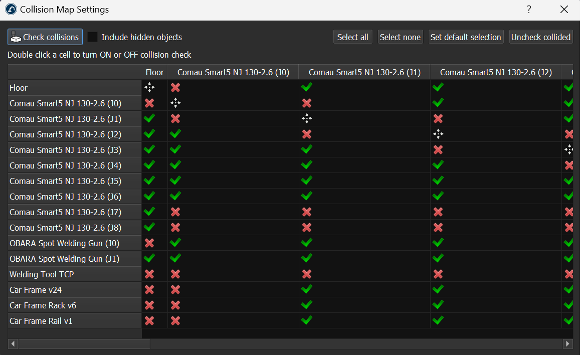
Collision detection
Once you have a path you can double check if there are any collisions and make sure you properly defined your collision map.
You can check if any parts collide by selecting Tools➔Check Collisions. This enables/disables collision detection.
You can then configure the collision map by selecting Tools->Collision map.
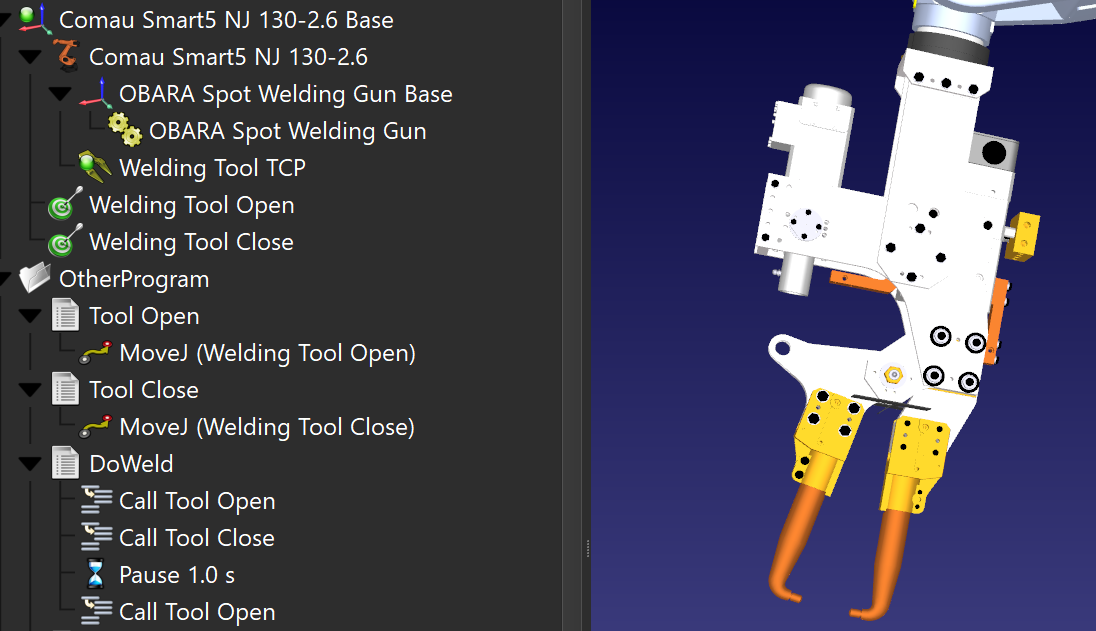
Program sequence
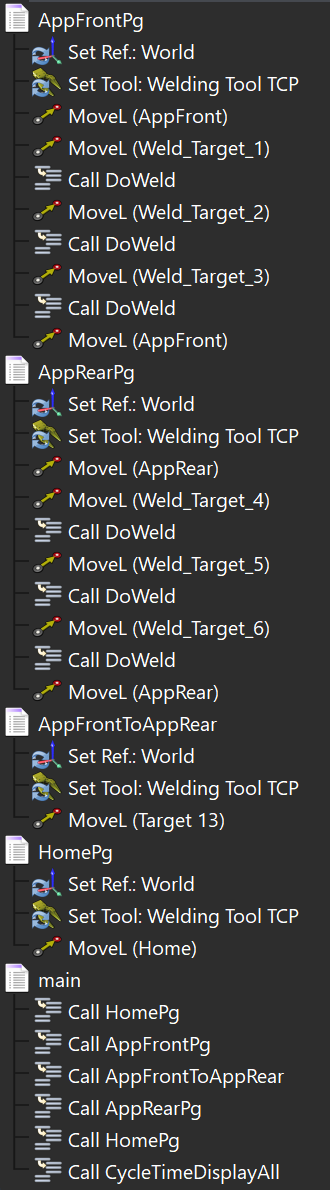
This section helps you create the spot welding sequence split in a main program and sub programs to keep the simulation and generated programs organized.
It is good practice to split the simulation into several programs to make it more convenient for future modifications and/or team collaboration. For this station, we use a main program with several routines:
Cycle Time estimation
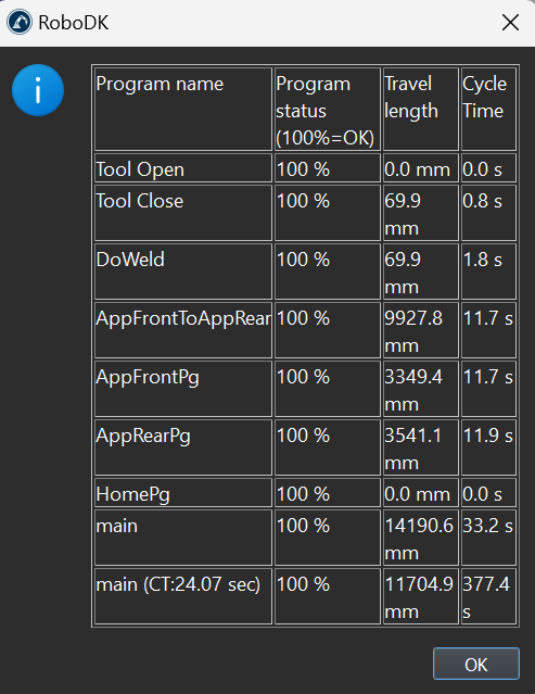
This section shows how you can calculate and display the cycle time estimate of the spot welding simulation.
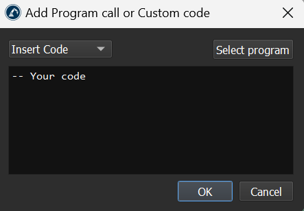
You can easily add time estimation to your program by just loading the CycleTimeDisplayAll.py script from the C:\RoboDK\Library\Scripts folder. You can then call it from the main program:
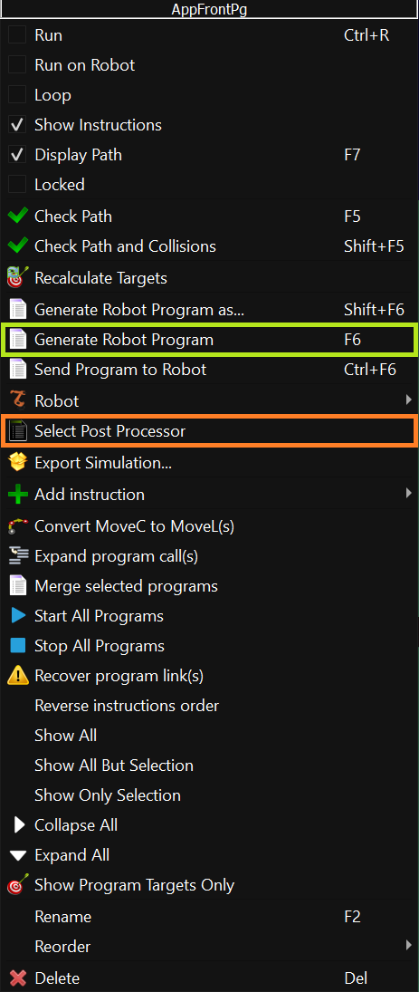
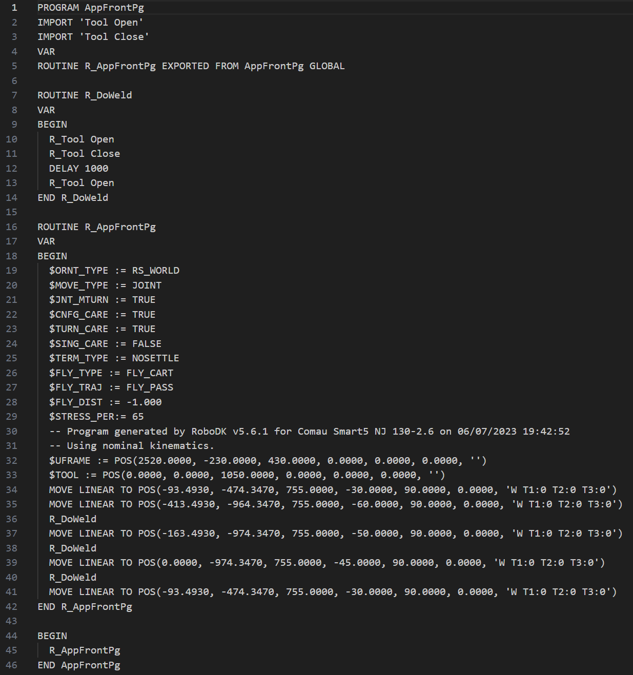
Generate Robot program
Once you have a valid simulation sequence for your spot-welding application you can generate the program with just a few clicks.
Select the program you would like to generate for your robot by right-clicking on the program and selecting Generate robot program.