Augmented Reality
Augmented Reality
Augmented Reality (AR) enables the ability to overlay elements of a RoboDK station on top of an input video or live video feed.
This feature is available in RoboDK by enabling the Image Processing Editor Add-In.
The Image Processing Editor features can be enabled navigating to Tools➔Add-In Manager and enabling Image Processing Editor.
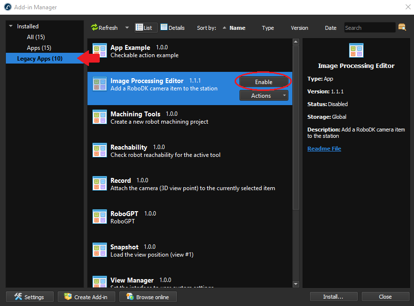
With the Image Processing Editor Add-In enabled, the station must now be prepared for Augmented Reality. The steps that need to be taken to create a successful AR render can be summarised into 3 sections:
1.Select and create a fiducial marker. Import the marker into RoboDK.
2.Create a simulated camera in RoboDK.
3.Create a detection pipeline.
Select and create a fiducial marker
The augmented reality add-in requires using markers to estimate the camera pose and trajectory.
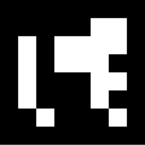
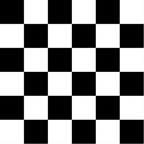
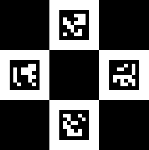
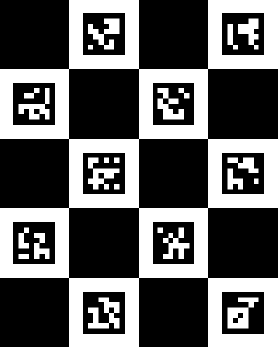
RoboDK supports 4 types of OpenCV markers: Aruco, Chessboard, Charuco Diamond, and Charucoboard respectively, as shown in the following images:
There are many factors to consider when selecting a marker. The size of the station, camera resolution, framerate, motion, lighting, and occlusion are important to consider. For example, a large station with a fixed, non-occluded camera will benefit greatly from using an Aruco marker as the single marker ID can be detected from much further than the 4 or more IDs on a Charuco Diamond or Charucoboard marker of the same size, and the lack of motion blur and occlusion can guarantee that the marker will be detected at all times. If the marker is occasionally partially occluded, the Charucoboard should be selected as it does not need all ID’s detected to determine the camera position. Below is a table assist in the selection of marker types:
Aruco | Charuco Diamond | Charucoboard | Chessboard | |
Pros | - Easier Set Up - Fastest Render Time | - Most Balanced Option (Accuracy/Render Time) | - Resistant to partial occlusion - Most Accurate | - Camera Calibration |
Cons
(Markers must remain in camera view at all times)
| - Loses tracking when occluded - Least Accurate Pose | - Loses tracking when occluded - Harder to Set-Up | - Long Render Times - Not good with Live AR | - Harder to detect - Cannot be occluded |
Suggested Applications | - High FPS / Low-res Live AR - Long Videos - Unobstructed Videos - Fixed Camera - Large Stations | - Better tracking for Live AR - High Resolution Videos - Slow Camera Motion | - Video containing partial occlusion of the marker - Videos with high pose accuracy requirements. | - Camera Calibration (The chessboard can be used to generate custom camera calibration files if the generic calibration is not sufficient) |
Once the appropriate marker has been selected, the marker ID’s, size and checkerboard layout and square size can be customized.
The marker must then be saved and printed. The “Save as…” function can be used to save a PNG of the marker on your computer, this can then be easily imported to RoboDK. To print the marker, the “Copy to clipboard” option can be used to quickly import the image into a text/image editor like Word or GIMP to be scaled to size and printed.
Import the marker
You should import the marker in RoboDK to indicate where the location of the marker is with respect to the robot and other objects.
Follow these steps to properly place the marker:
1.In your RoboDK station, create a new reference frame.
2.Right-Click the new reference frame and select “Add Item…”.
3.Find and select the marker PNG created with the Fiducial Marker Generator.
4.Adjust the scale of the virtual marker to match the size of the real marker:
Example: The Charuco Diamond marker is 106.186mm x 106.186mm by default. If the size of the printed marker is 280mm x 280mm, then a scale factor of 2.63688 → ( 280 / 106.186 ) must be applied. This can be done by double-clicking the marker object, selecting More Options ➔ Apply Scale.
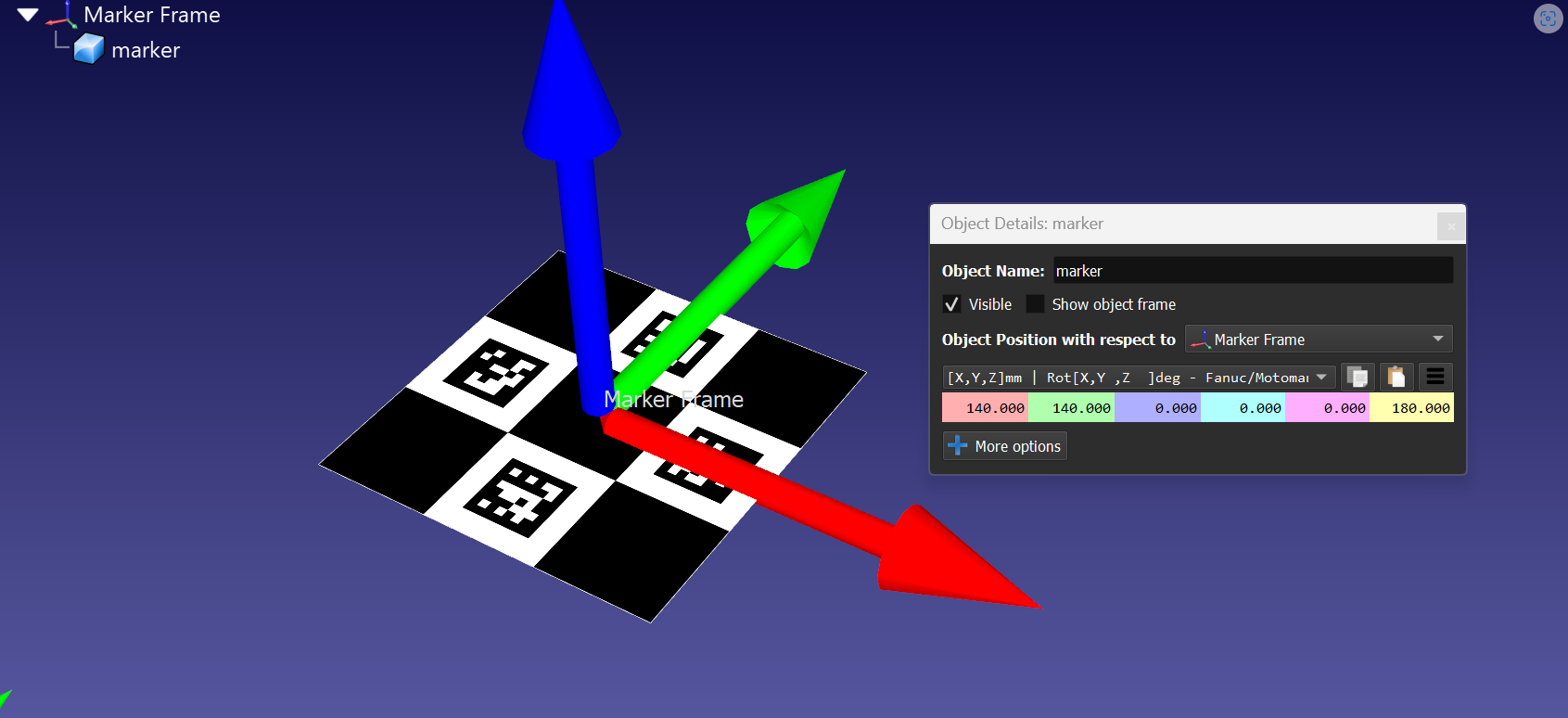
5.Align the center of the marker to the reference frame origin, with the Y axis pointing to the top ID.
Example: To move the marker, double click the marker object and modify the object position with respect to the marker frame. For our example, the marker needed to be moved 140mm on X, moved 140mm on Y, and rotated 180° on the Z axis. See image below for an example of the correct position.
6.Place the marker frame in the station to align station objects relative to the marker.
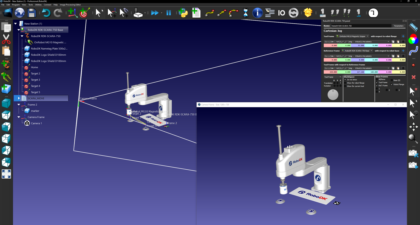
Set up the simulated camera
To accurately overlay the station assets over the video feed, a simulated camera must be created. This simulated camera uses the camera pose and trajectory calculated using the fiducial markers to record the RoboDK station from the same angle, distance, and trajectory as the input video feed.
This simulated camera resolution needs to match the input video for the marker scaling to be accurate. The steps to add a virtual camera to the station are outlined below:
1.Add a camera to your station by selecting Image Processing Editor ➔ Add a RoboDK Camera in the toolbar.
2.Right-Click on the camera or camera feed and select “Camera Settings”.
3.Adjust the virtual camera settings to match the resolution of the input video feed.
4.Align the reference frame so that the simulated camera can see the virtual Aruco marker.
For the best results, the physical input video should be recorded with the following considerations:
1.Place the marker on a flat surface in a well-lit environment. For optimal results, consider the size and distance of the objects in the virtual station respective to the marker and recording environment.
2.Consistent Camera Settings (Real and Simulated Cameras must have matching resolution settings).
3.Legible Aruco ID’s (Camera must keep ID’s legible. Things to avoid: Fast/Blurry Footage, Low camera resolution, High marker distance from camera).
4.Ensure the video is in .mp4 or .avi format
Create a custom camera calibration file
To create a custom camera calibration file, print out a chessboard and take around 10-20 images of the chessboard with the camera, using the same settings as when filming a video.
Each image should contain the entire chessboard. The images should vary the orientation and location of the chessboard in each image.
Once the images have been taken, navigate to Image Processing Editor ➔ Calibrate from files… and fill out the chessboard parameters. Then select the images. RoboDK will generate a calibration file that can be used when creating a pipeline.
Create a detection pipeline
The final step to preparing the RoboDK station for AR is to create a pipeline to detect the fiducial markers. This detection pipeline will be used to calculate the pose from the real and virtual markers and overlay the assets from the simulated RoboDK camera on top of the input video feed.
Follow these steps to create a detection pipeline:
1.Navigate to Image Processing Editor ➔ Image Processing Editor in the toolbar.
2.Select the simulated RoboDK Camera if using Video AR, for Camera AR select the camera source.
3.Select your marker under Detectors ➔ Charuco Diamond Markers.
4.Set the required parameters based off the physical marker dimensions.
5.Under Device, Set the calibration file. It is recommended to use Generic Calibration.
6.Save the pipeline project under File ➔ Save Project As…
With the station prepared, an input video recorded, and a processing pipeline saved, we can begin making AR videos. The next sections detail how to create AR videos and live AR renders as well as a troubleshooting section to aid in fixing undesirable renders.
Create an AR from a video feed
The Video AR tool is used to create an AR overlay on top of a pre-recorded video. This is ideal for demonstration or promotional videos. The station can be modified while the video is rendering, and the changes will be applied immediately.
Follow these steps to create AR overlaying effects on a Video:
1.Hide all objects in your station you do not want rendered into the AR video.
2.Select Image Processing Editor → AugmentedReality (Video).
3.If multiple pipelines are saved, select the correct pipeline for your marker.
4.Select the reference frame containing the marker.
5.Select the input video file.
6.Select the location and name of the output video.
7.Monitor the rendering process and make any changes necessary to achieve the desired quality.
8.Once the video has completed rendering, you can close the AR Camera Frame.
Mixed Reality
Mixed Reality (MR) in RoboDK refers to replacing the RoboDK background with a live passthrough feed from VR headset. Doing this in RoboDK VR enables the mixing of your local environment, SteamVR, and RoboDK.
Requirements:
●Quest 2 / Quest 3 VR Headset and a VR Capable PC
●Virtual Desktop + Virtual Desktop Streamer
●SteamVR + Meta Quest Link
Follow these steps to enable Mixed Reality:
1.Enable the Quest 2/3’s Developer mode:
How To Activate Developer Mode On The Meta Quest 3? (vr-expert.com)
2.Launch Meta Quest Link on your PC and follow the instructions to link your headset to the PC:
Set up and connect Meta Quest Link and Air Link | Meta Store
3.Connect to your PC using Virtual Desktop
4.In the Virtual Desktop application enable the VR Passthrough API.
5.Modify the VR Passthrough settings: Set the Passthrough mask colors to 0, 255, 0 (Green).
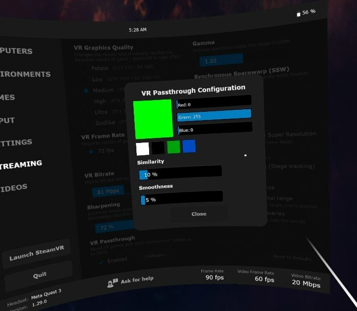
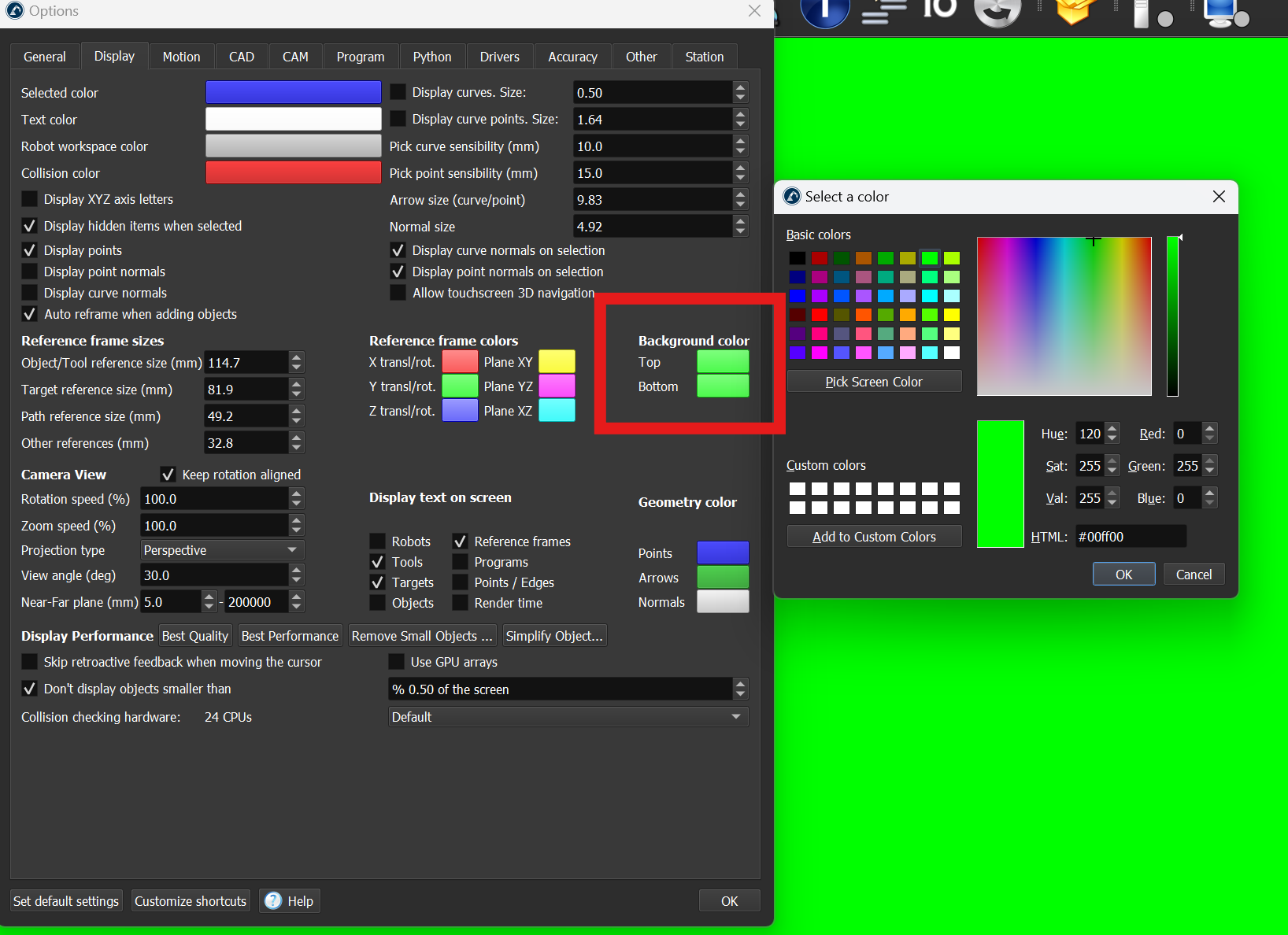
6.In RoboDK, set the top and bottom background options to the same shade of green:
Tools -> Options -> Display -> Background Color -> Set to 0, 255, 0 (Green)
7.Launch SteamVR through Virtual Desktop.
8.Launch RoboDK and enable the VR mode: Connect ➔ Connect VR headset.