Collision Detection
Collision checking with RoboDK can help you prevent collisions in your real setup. Collision checking can be used in different ways such as visually checking collisions, automatically avoid collisions for robot machining projects or generate a collision-free map to automatically create collision-free programs.
This section covers the following topics:
●How to activate collision checking for your simulations.
●How to define a collision detection map.
●How to activate automatic collision detection and avoidance for robot machining projects.
●How to automatically create collision-free programs to link different targets or other programs using a PRM algorithm.
Collision Detection
Select Tools➔
Follow these steps to safely check a program for collisions:
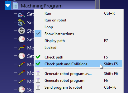
1.Right click a program.
2.Select Check path and Collisions (Shift+F5). This option quickly checks if the path is feasible (same as Check path – F5) and then validates that there are no collisions.
Collision Map
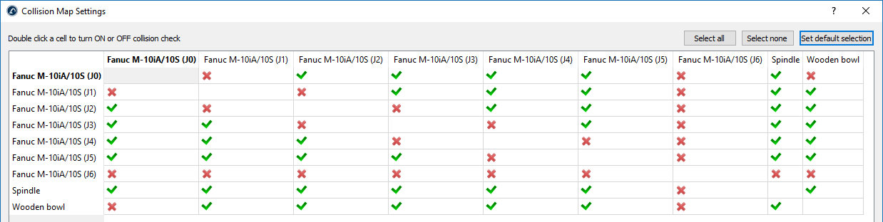
You can specify if the interaction between any pair of objects needs to be checked for collisions.
Select Tools➔
By default, RoboDK checks collisions between all moving objects in the station, including all robot links, objects and tools. As an exception, consecutive robot joints are not checked for collisions as they may always in contact.
Faster Collision Detection
Collision detection speed highly depends on many factors.
1.The number of pairs of checks defined in the collision map. Having a collision map with less checks will be faster.
2.The robot step used for collision checking. The collision step can be modified in the Tools➔Options➔Motion menu. Linear movements use the step in millimeters and joint movements use the step in degrees. A larger step will provide faster collision checking but the result may be less accurate.
3.Computer power: more computer power (faster CPU) and more processing threads will allow you to have faster collision checking.
4.The complexity of the 3D files. Geometries with higher level of detail, such as rounded areas, usually require more computation power. Simplifying these geometries and reducing the number of triangles will help you speed up collision checking.
You should consider the following guidelines for better collision checking:
1.Choose STEP or IGES formats over STL files for better performance and compatibility.
2.Simplify geometry as much as possible.
3.Use the simplify mesh addin to automatically simplify complex geometry: https://robodk.com/addins.
4.To identify improperly grouped features, enable bounding box previews via Tools➔Options➔Other➔Draw bounding boxes (when collision check is activated). Ensure bounding boxes do not encompass multiple separate elements.
5.Avoid using the “Simplify Object…” feature found in Tools➔Options➔Display. It consolidates all surfaces into a single element, resulting in one extensive bounding box, which goes against the previous point.
6.Have collision-specific objects in the environment: duplicate objects and remove surfaces that cannot be reached, or import a version with simpler geometries (e.g., convex hulls). Use the original object for visual purposes only and exclude it from the collision map.
7.Using the API, dynamically update the collision map or set items invisible when they should not be part of the collision detection.
Collision Avoidance for Robot Machining
You can enable automatic collision avoidance for robot machining projects. RoboDK will automatically rotate the tool to find a collision-free path.
Follow these steps to activate automatic collision checking and collision avoidance for robot machining projects:
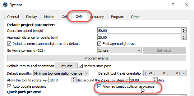
1.Select Tools➔Options➔CAM
2.Check Allow automatic collision avoidance
3.Double click your robot machining project, 3D printing, curve follow or point follow project.
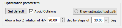
4.Check Avoid collisions: this will activate automatic collision avoidance by changing the tool orientation around the Z axis as described in the optimization parameters.
Collision-Free Motion Planner
The motion planning feature automatically creates collision-free paths within the robot's workspace. In RoboDK, this feature uses a motion planning algorithm called "probabilistic roadmaps" (PRM).
First, a map is created of the free space in the robot's workspace. This map is then used to quickly generate collision-free trajectories during robot programming.
PRM algorithms are characterized by the following two properties:
●Probabilistic: The points in the "configuration space" (i.e. the set of points that the planner uses to know where the robot can move in its workspace) are chosen randomly by the planner. This makes PRM algorithms quicker than other motion planning algorithms which try to cover the entire workspace equally.
●Roadmap: PRM algorithms work by first creating a "roadmap" of the entire robot workspace.
For a more general introduction to robot motion planning, please refer to this blog post.
Using the PRM Motion Planner
There are two distinct phases when using PRM motion planning. These are performed separately in RoboDK, which improves the efficiency of the feature. The slower "construction phase" only needs to be performed once, whilst the quicker "query phase" can be repeated many times.
The two phases are:
- Construction phase (slow) — The PRM algorithm randomly places points within the robot's free workspace. It then tries to connect these points together, to form a roadmap of collision-free paths within the workspace.
- Query phase (fast) — The planner tries to find the shortest collision-free path between two target points by using the roadmap created in the construction phase.
For more information about how the RoboDK PRM algorithm works, please refer to this blog post.
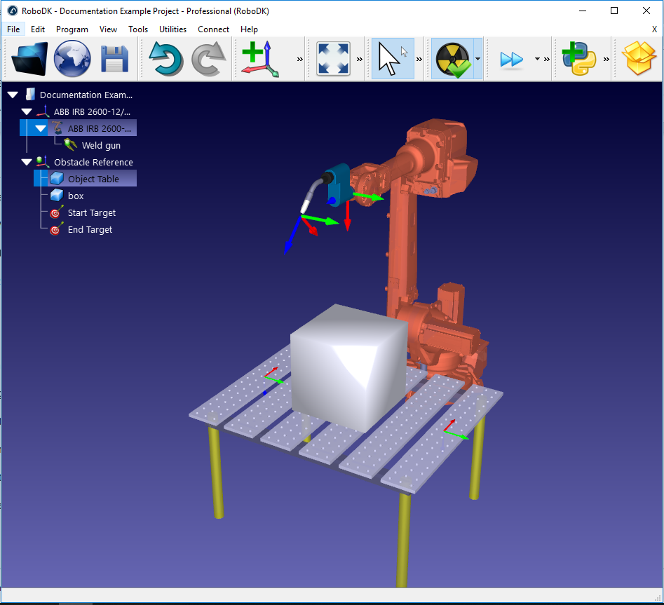
This section shows how to use both of these phases in a RoboDK program. An example welding setup is used to demonstrate the functionality.
Setup for Motion Planning
To use the motion planner, there needs to be a robot, ideally with a tool. It also makes sense to have at least one object within the workspace otherwise collision-avoidance is not needed. It can be helpful to have at least two targets assigned which will serve as the start and end locations for the generated collision-free path.
The example welding setup can be created using the following process:
1.Select a robot:
a.Select File➔
b.Use the filters to find your robot. For example, select the ABB IRB 2600-12/1.85 (choose the following filters: ABB (brand), 10-20 kg payload and 1500-2000mm reach.
c.Select Download and the robot should automatically appear on the main screen.
2.Select a tool:
a.From the same online library, filter by Type➔Tool (click Reset filter first to remove the previous filters)
b.Download a tool, e.g. the "Weld Gun"
c.The tool should be automatically attached to the robot
d.Once the tool is loaded, the Online library can be closed
3.Add a reference frame:
a.Select Program➔
b.Select the new reference frame in the tree and press F2 to rename it to "Obstacle Reference"
4.Add some objects:
a.Select File➔
b.Select an object, such as the "Object Table.wrl"
c.Drag and drop the object onto the Obstacle Reference within the station tree.
d.Select another object, such as "box.stl" and drag this onto the Obstacle Reference also.
e.Move the table in front of the robot by doing the following:
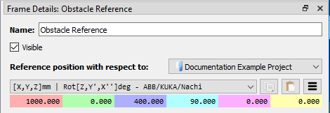
i.Right click on the Obstacle Reference and choose "Options" (or just double click on the reference in the tree) to bring up the Frame Details panel
ii.Enter the following values in the panel named Reference position with respect to: Project: 1000, 0, 400, 90, 0, 0
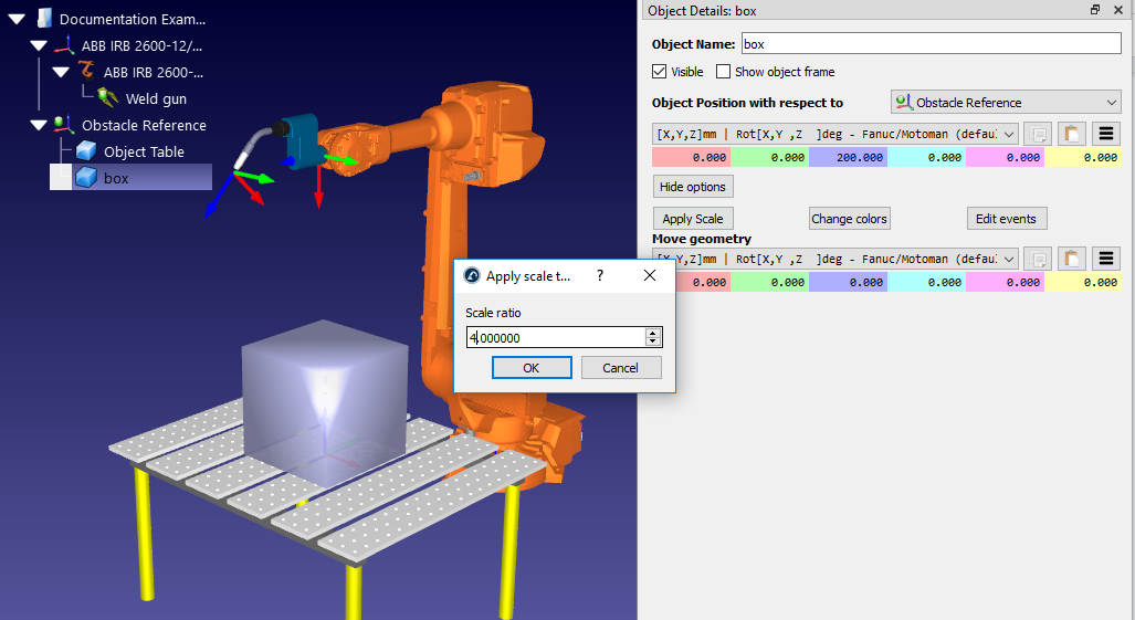
f.If necessary, increase the size and position of your object (e.g. the "box") by following these steps:
iii.Right click on the object in the station tree and choose Options (or just double click on the object in the tree) to bring up the Object Details panel
iv.Scale the box by clicking More options…➔Apply Scale and enter "4.0" in the Scale ratio
v.Move the box onto the table by entering the following values in the panel named Object position with respect to Obstacle Reference: 0, 0, 200, 0, 0, 0
5.Create targets:
a.Select Program➔
b.Select the new Target in the station tree and select F2 to rename it to Start Target
c.Move the target by doing this:
vi.Right click on the target in the station tree and choose Options (or press F3) to bring up the Start Target panel.
vii.Enter the following values in the Target position with respect to Obstacle Reference panels: 500, 0, 0, 90, 0, 180
d.Create a second target, in the same way, and rename it End Target. Using the same method as before, move it to the location: -500, 0, 0, 90, 0, 180
Constrain Joint Limits
It is unusual that a task will use all the robot's workspace. When creating a PRM map, it is often a good idea to constrain the robot's joint limits. This will speed up the process of generating the map and ensures that the points within that map are located in the best place.
For 6-axis robots, the two joints which are most often restricted are:
1.Joint 1 (the base joint): Restricting this joint stops the robot from moving too far to either side of the workspace.
2.Joint 3 (the elbow joint): Restricting this joint stops the robot from changing between elbow-up and elbow-down configurations.
Change the joint limits using the following process:
1.Right click on the robot model icon within the station tree (e.g. ABB IRB 2600-12/1.85) and select Options… to open the robot panel. Alternatively, just double click on robot name in the station tree.
2.In the Joint axis jog section, move the sliders of the robot joints you want to restrict (e.g. θ1 and θ3) to find where you want the lower joint limits to be.
3.Double click on any of the lower joint limits within the Joint axis jog. For example, if the joint limit of θ1 is currently -180, double click on the number -180. This will bring up the Set lower joint limits panel.
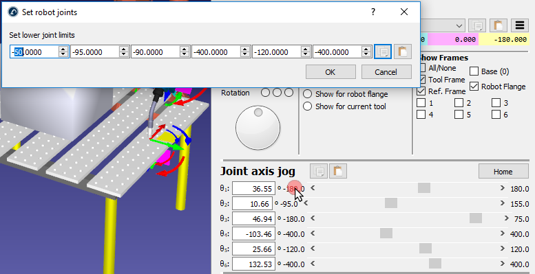
4.Set the lower joint limits to θ1 = -50 and θ3 = -90.
5.Change the joint limits and click OK.
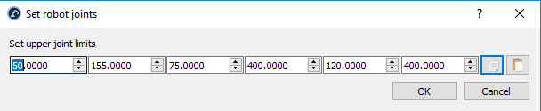
6.Using the same process with the upper joint limits, set θ1 = 50.
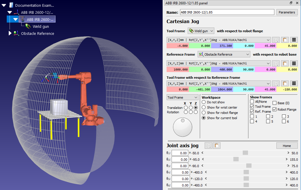
This change can be seen by viewing the robot's reachable workspace. Show the workspace by selecting the Show for current tool option in the WorkSpace section of the robot panel. It will show only the part of the workspace is now reachable with the new joint limits.
Select the PRM Parameters
The PRM algorithm generates a roadmap of reachable locations using the following three parameters:
1.Number of samples — The map consists of a number of randomly placed locations (samples) throughout the robot's reachable workspace. This number determines the number of samples. The default is 100 samples.
2.Edges per sample — The algorithm attempts to connect every sample in the map with a number of other samples. The line which connects two samples together is called an "edge" and indicates a collision-free path between those two locations. This property indicates the maximum number of edges that will be created per sample. The default is 25 edges per sample.
3.Robot step (deg) — When checking if a potential edge is collision-free, the algorithm will stop at regular intervals along it to check for collisions. The distance between these intervals is determined by the robot step. The default is 4 degrees.
These three parameters determine how detailed the generated roadmap will be. They also affect how long it takes to generate the roadmap during the construction phase.
A larger Number of samples and more Edges per sample will produce a finer-grained roadmap which will take longer to generate. A larger Robot step will generate a map quicker but may fail to detect potential collisions.
Using the default values, a roadmap can usually be generated within 15 minutes, depending on the setup of the workspace and properties of the robot.
See the tips at the end of this section for best practices when setting these parameters.
Generate Roadmap
The "construction phase" of the motion planner is achieved using the following process, which generates a roadmap of the robot's workspace:
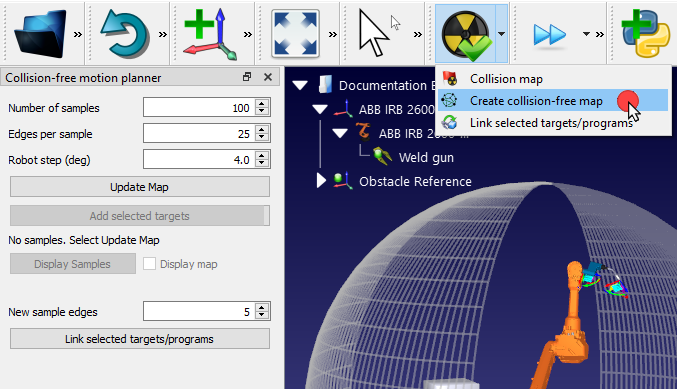
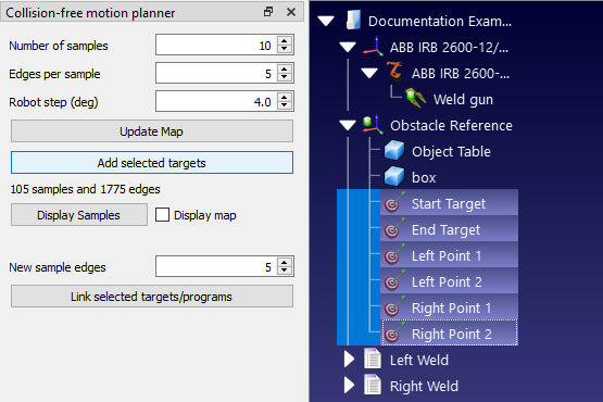
1.Open the Collision-free motion planner panel by either going to the Utilities menu➔Collision-free motion planner➔Create collision-free map or click on the small arrow next to

2.Enter new parameters or keep the defaults.
3.Click on Update Map to generate the roadmap.
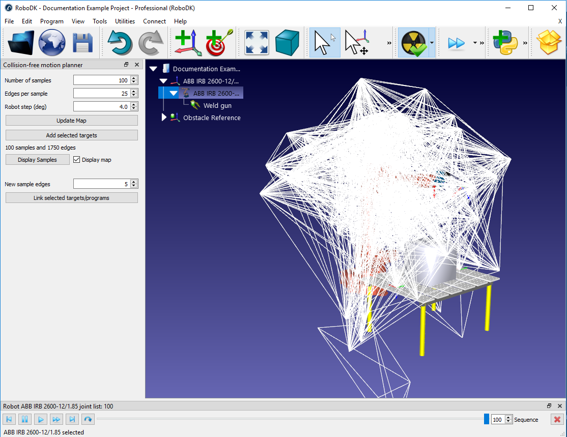
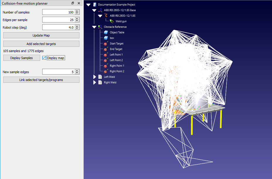
The PRM algorithm will then generate a roadmap using the chosen parameters. When it is finished, the generated roadmap can be viewed by checking the box Display Map. Clicking Display Samples will move the robot through all samples within the workspace.
Link Targets
The "query phase" of the motion planner is accessed when two targets or programs are linked together.
To link two targets, first select them in the station tree. There are two ways to select and link the targets:
1.With the Ctrl key:
a.Left click on the target which is to start the movement (in the example, the target named "Start Target").
b.Hold down the CTRL key.
c.Left click on the destination target (e.g. "End Target")
d.Right click on either of the two targets and select Link selected targets. Alternatively, if the Collision-free motion planner panel is open, click on the Link selected targets/programs button.
2.With the Shift key:
a.Arrange the two targets one above the other in the station tree, with the start target above the end target. A target can be moved around the tree by drag-and-dropping it using the right mouse button. Dropping the target will reveal a menu to choose where the target should be located.
b.Left click on either target.
c.Hold down the Shift key.
d.Left click on the other target.
e.Right click on either of the two targets and select Link selected targets. Alternatively, if the Collision-free motion planner panel is open, click on the Link selected targets/programs button.
Both methods will generate a new program which links the two targets using the saved roadmap. To create a movement in the opposite direction, select the targets in the opposite order — i.e. by selecting End Target before Start Target using the Ctrl method, or rearranging the targets in the station tree for the SHIFT method.
Link Programs
The motion planner can also link two different programs together in a similar manner. This creates a collision-free path between the two programs and creates a new Main program.
For the welding example, create two dummy programs using the following process:
1.Create 4 targets as children of the "Object Reference" reference frame (right-click on "Object Reference" in the station tree and check Active Reference Frame). Then create four targets by choosing Program 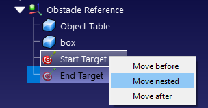
2.Select each new target in the station tree and enter the following names and values. To change the target name, press the F2 key or right-click the target and choose Rename. To change the target values, press the F3 key to bring up the Target panel or right-click the target and choose Options. Enter the new values in the section marked Target position with respect to: Object Reference.
a.Name: "Left Point 1" Values: 200, 200, 0, 90, 0, -135
b.Name: "Left Point 2" Values: 200, -200, 0, 90, 0, -135
c.Name: "Right Point 1" Values: -200, 200, 0, 90, 0, 135
d.Name: "Right Point 2" Values: -200, -200, 0, 90, 0, 135

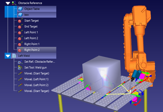
3.Create the first program:
a.Go to Program➔ 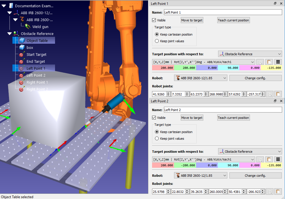
b.Rename the program to "Left Weld" by first selecting the program in the station tree and either pressing F2 or right-clicking and selecting Rename.
c.Add the following targets as linear instructions, by first selecting the target in the station tree and selecting Program➔
4.Create the second program called "Right Weld" in the same manner, this time adding the following targets: End Target, Right Point 1, Right Point 2, End Target.
Note that these two dummy programs do not contain commands to activate/deactivate the weld gun. In a real program, these commands would have to be included.
To link any two programs using the motion planner, use the following process:
1.Select both programs using either of the two methods described in the previous section (Link Targets).
2.Right click on either of the programs and choose Link selected programs. If the collision-free motion planner panel is open, the same can be achieved by clicking on Link selected targets/programs.
A new program called "MainSafe" will be created which runs the first program, makes a collision-free move, then runs the second program. This main program can be altered and renamed just like any other program.
Add New Targets to Map
Any new target can be added to the PRM roadmap without having to regenerate the entire map. This means that the roadmap only needs to be completely regenerated if new objects are added to the workspace or existing objects are moved around.
When a new target is added to the roadmap, the PRM algorithm will attempt to connect it to a number of existing points already within the roadmap with a set of new edges. It is possible to set a different default number of edges for new targets than the number chosen for the initial roadmap construction.
The maximum number of edges for new targets can be set using the following process
1.Open the Collision-free motion planner panel by either going to the Utilities menu➔Collision-free motion planner➔Create collision-free map or click on the small arrow next to 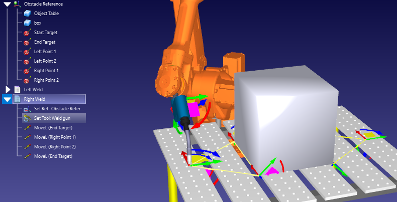
2.Enter the number of edges in the box labeled New sample edges. The default is 5.
There are two ways to add new targets to the roadmap:
1.Select the targets in the station tree. Multiple adjacent targets can be selected at once by clicking on the highest target, holding the Shift key, and then clicking on the lowest target. Multiple non-adjacent targets can be selected by holding the Ctrl key. Then click Add selected targets in the Collision-free motion planner panel.
2.Simply use the same method to Link selected targets or Link selected programs described in the previous sections (Link Targets and Link Programs). Any target which is not already present in the roadmap will be added automatically.
Tips and Best Practices
The motion planner is easy to use, but there are some best practices which will improve the programming workflow.
The construction phase can take a long time to run. This can become cumbersome during the early stages of programming when the layout of the robot cell is changing constantly. Every time an object is added to the workspace or moved around, the entire roadmap needs to be re-generated.
To reduce the time spent waiting for the roadmap to be generated, it is a good idea to use smaller parameters at first.
For example, you can usually generate a collision-free map with the following within 10-15 seconds:
1.Number of samples: 10.
2.Edges per sample: 5.
3.Robot step (deg): 4.0.
This will not produce the most efficient collision-free motion, but it will allow the cell design to be altered much quicker.
When the locations of all objects in the cell have been decided, then a larger map can be generated (e.g. with the default parameters of 100, 25, 4.0).
Finally, before generating the robot program, it may be a good idea to generate an even larger roadmap (e.g. with parameters of 500, 50, 2.0). This will take a long time to generate but will produce the most efficient motions.
Setting the robot joint limits (as described in the previous section Constrain Joint Limits) has a dual benefit. Firstly, it can make the construction phase quicker in some cases. Secondly, it ensures that the roadmap actually contains locations which will be useful for the robot program. It is easy to forget about this vital step.
Properly define the collision map
Collision detection is triggered when 2 objects collide. You can specify the correlation between each moving object in the Collision Map settings. Reducing the number of interactions (green check marks) will speed up collision checking.
The time it takes to calculate collision-free paths mostly depends on the time required to check for collisions. Therefore, you should follow the best practices for faster collision checking described in the collision detection section. Among other things, you can increase the robot step for collision checking, constrain the joint limits or simplify the 3D geometry to speed up collision checking.
The term "collision-avoidance" suggests that the motion planner will always avoid collisions in all situations. This is certainly true in the simulation environment. However, in the real world, the robot can still collide with objects if it comes too close to them. This usually occurs because of slight differences between the simulated robot and the physical robot.
A common instance of such collisions is when the robot "clips" the edge of an object when moving away from a task. This can usually be avoided by including an "offset" in the program. See this blog article for more information about using offsets effectively.
Not all areas of the robot's workspace are equal. The robot will have more "reachability" in some areas of its workspace than others. In areas with high reachability, the robot will be able to access points from many orientations. In areas with low reachability, the robot will only be able to access points from one or two orientations.
Sometimes, the motion planner will fail to find a path between two targets in the workspace. Often, this problem can be solved by simply increasing the number of samples in the roadmap, but not always.
If the motion planner continually fails to connect targets, ensure that the task is located within the area of the robot's workspace with most reachability. View the robot's workspace by opening the robot panel (right click on the robot in the station tree and choose Options) and selecting Show for current tool in the WorkSpace section.