Robot Machining
Introduction
This example will help you understand the basics of robot machining in RoboDK and how to convert a 3-axis robot machining job to a robot machining simulation and robot program.
Once you have defined your machining strategy with your CAM software, you can export your machining program as a Gcode or as an APT file so that you can load it in RoboDK to create a robot machining project. In this example, we will be using an APT file to create a robot machining project.
You can find this sample RoboDK project int the following location C:/RoboDK/Other/Plugin-MecSoft/Mold-Core.rdk.
Robot Machining Example (3-Axis)
In this example, you will learn how to convert a machining program to a robot machining simulation and a robot program. More specifically, you will learn how to generate robot programs valid for your robot controller from NC files such as an APT file.
Machining program in RhinoCAM
This section shows how you can export a machining job from Mecsoft RhinoCAM software to RoboDK. An APT file is used to load the toolpath in RoboDK and automatically sent using a custom BAT file.
Follow these steps in RhinoCAM to export the machining job to RoboDK:
1.Right click your machining job project from RhinoCAM.
2.Select Post All to generate the machining programs and automatically load everything in RoboDK.
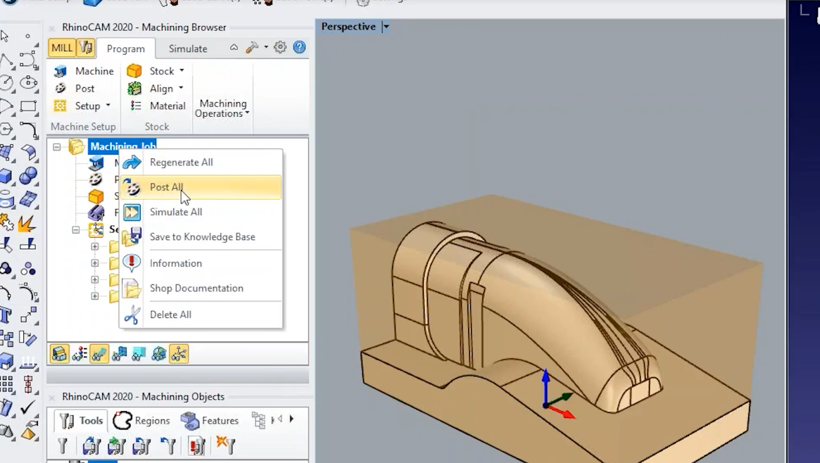
You can see that RoboDK automatically splits the robot machining program in the same 4 machining operations we created in the CAM software.
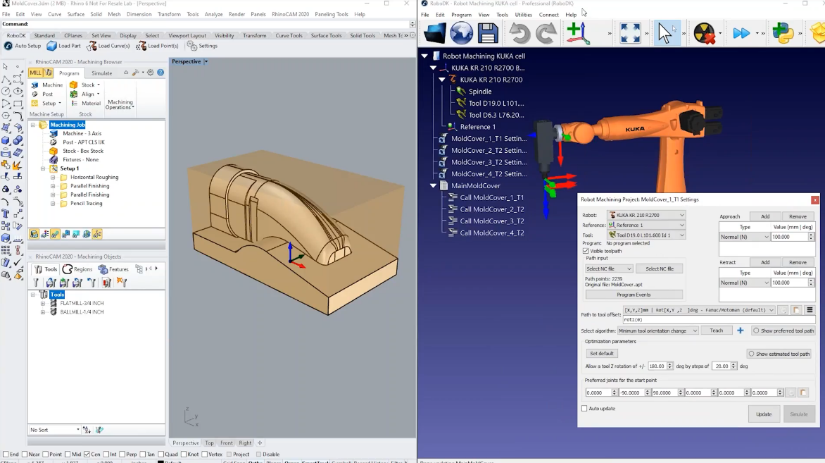
The robot machining project is created using a default robot cell that we can customize. In this example we use a KUKA robot and a default spindle where the tool (or TCP) represents the tool holder.
By default, when loading APT programs, RoboDK will add the tools you define in your machining project. The tools will be added to your active TCP when you load the APT file. The correct tools will also be preselected in your robot machining project.
Robot machining project (3x)
This section shows how to customize the robot setup and the machining toolpath to successfully accomplish robot machining. RoboDK’s machining project allows you to convert any generic 3 axis or 5 axis manufacturing operation to a robot simulation and a robot program.
Since we loaded the machining file directly, everything has been created and selected automatically. We can also customize the approach and retract movements in RoboDK.
Create Robot Machining Path
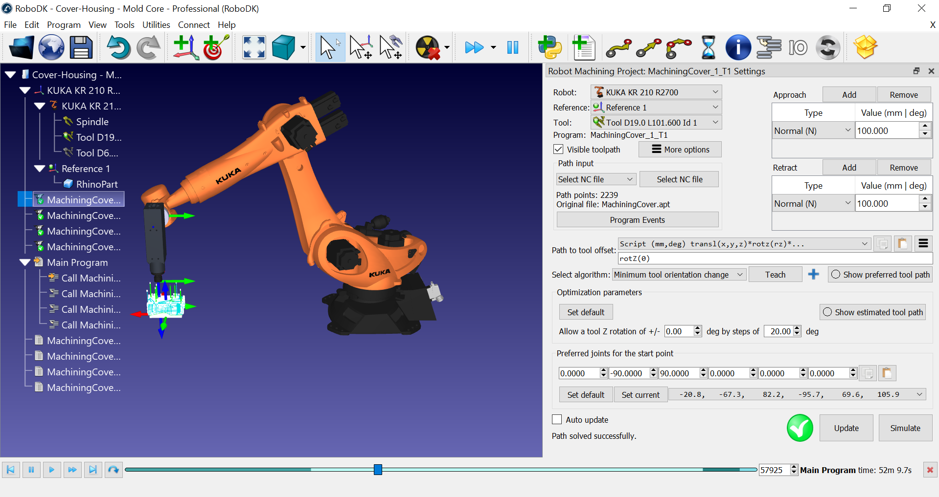
You can create the robot machining simulation in RoboDK once you loaded the APT file by selecting Update. This allows you to see if the robot can perform the manufacturing operation.
This example is a simple 3 axis machining operation, and the default settings give us a valid result. The robot machining project allows you to control how the robot behaves along the machining toolpath.
You can follow these steps to update the remaining robot machining operations:
1.Select one or more robot machining operations (holding Shift allows you to generate multiple items in the tree).
2.Right click the selected item(s).
3.Select Update programs.
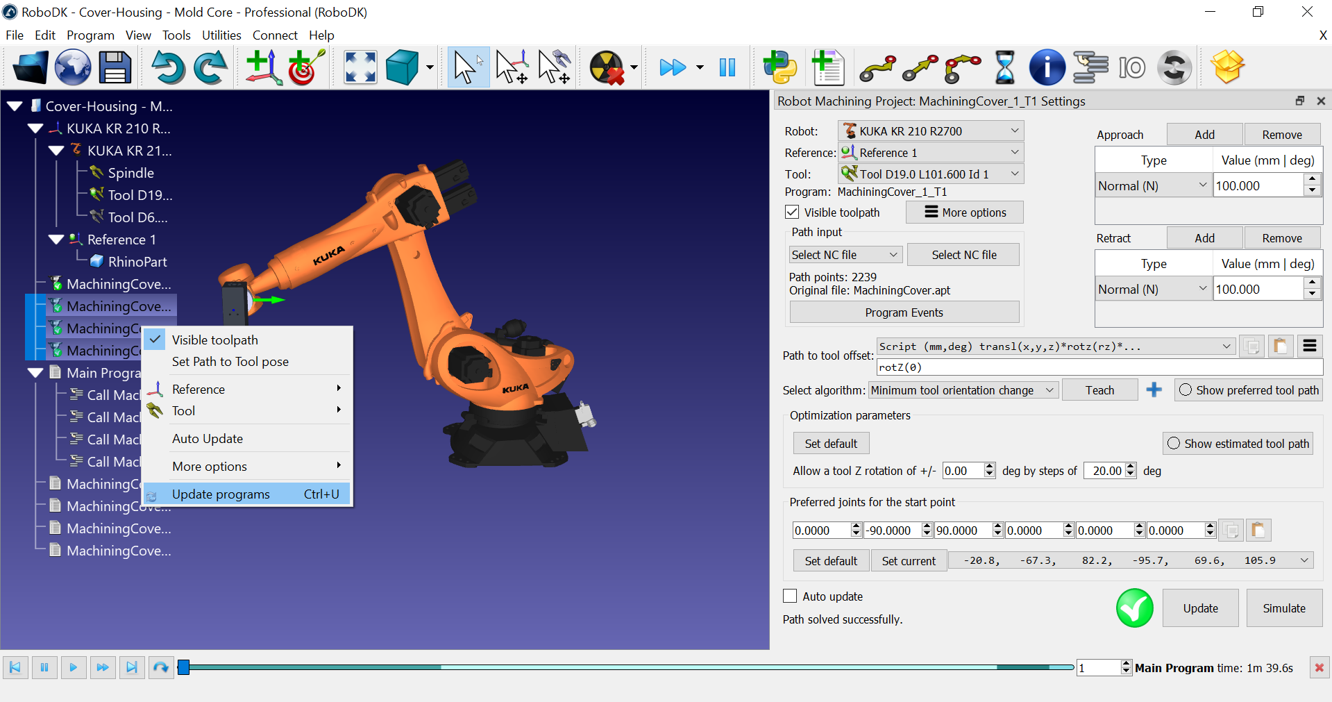
As RoboDK calculates the robot machining path, it will create one new robot program for each machining operation. The white icons represent robot programs. These programs are automatically created by RoboDK. You can simulate each program individually by double clicking it on the tree.
RoboDK also automatically creates a main program that you can run to simulate all robot machining operations in order.
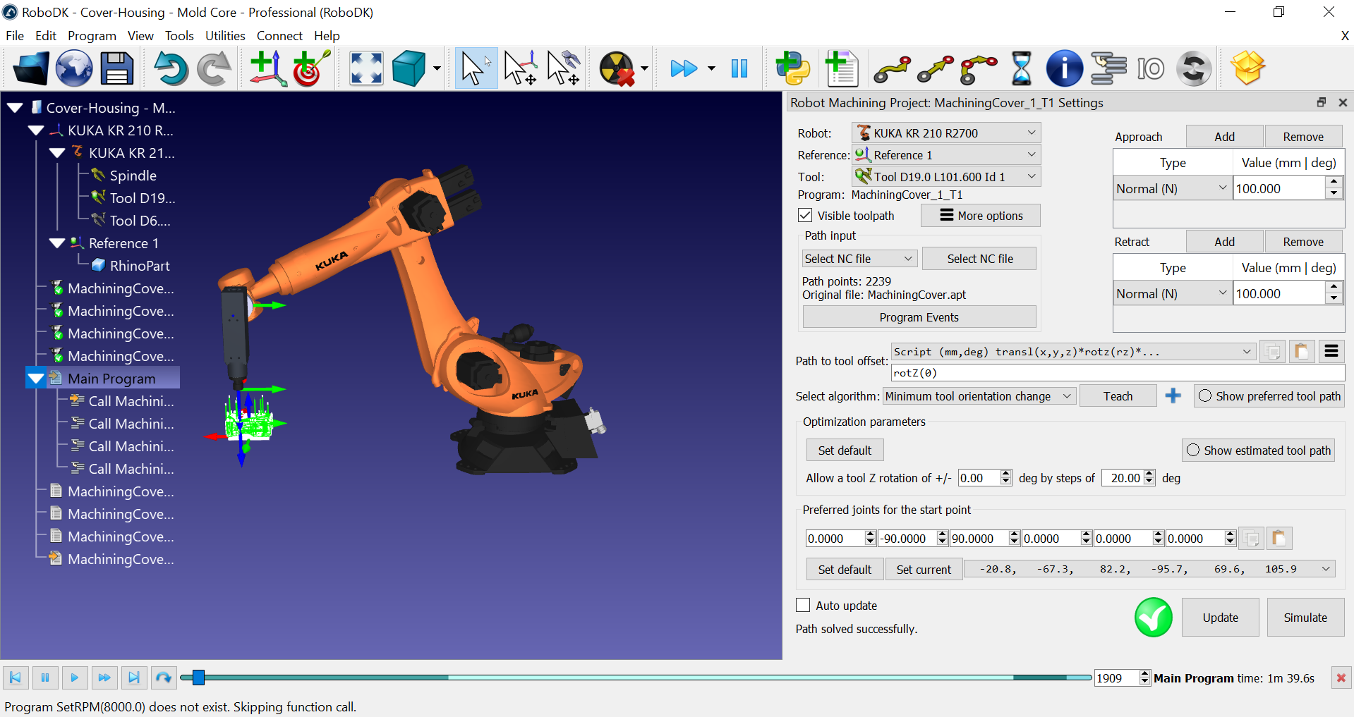
Simulate the robot machining operation
You can double click the Main Program to simulate the whole robot machining operation. You can also double click any sub program to simulate it.
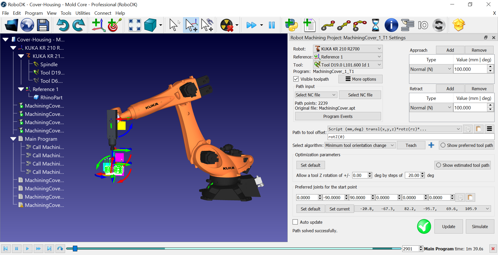
Customize the tool orientation
Most machining or manufacturing operation involve a 5 axis constrain. While the position of the tool (TCP) and the cutting axis is defined, you have an additional degree of freedom to define when you use a 6-axis robot arm. This degree of freedom allows us you to turn around the cutting axis and automatically avoid singularities and axis limits.
The easiest way to customize the tool orientation is by selecting the Teach button in the robot machining project. By selecting Teach, you are telling RoboDK you want to follow the current tool orientation so the settings will adjust to match that orientation.
By selecting Show preferred tool path we can preview the tool orientation the robot is trying to follow.
You can select Update and Simulate to see the result.
The optimization parameters allow the robot to automatically change the tool orientation if the robot can't achieve the preferred orientation. This parameter is important if you have a large part, if you are working near a singularity or near the limits of the robot workspace. If you see a red mark it means the robot cannot perform the operation.
If you select Show estimated tool path you should see in green the positions that are reachable. It will give you a hint about what the orientation will look like to make the path feasible. This means we are using the additional degree of freedom to automatically avoid robot singularities and axis limits.
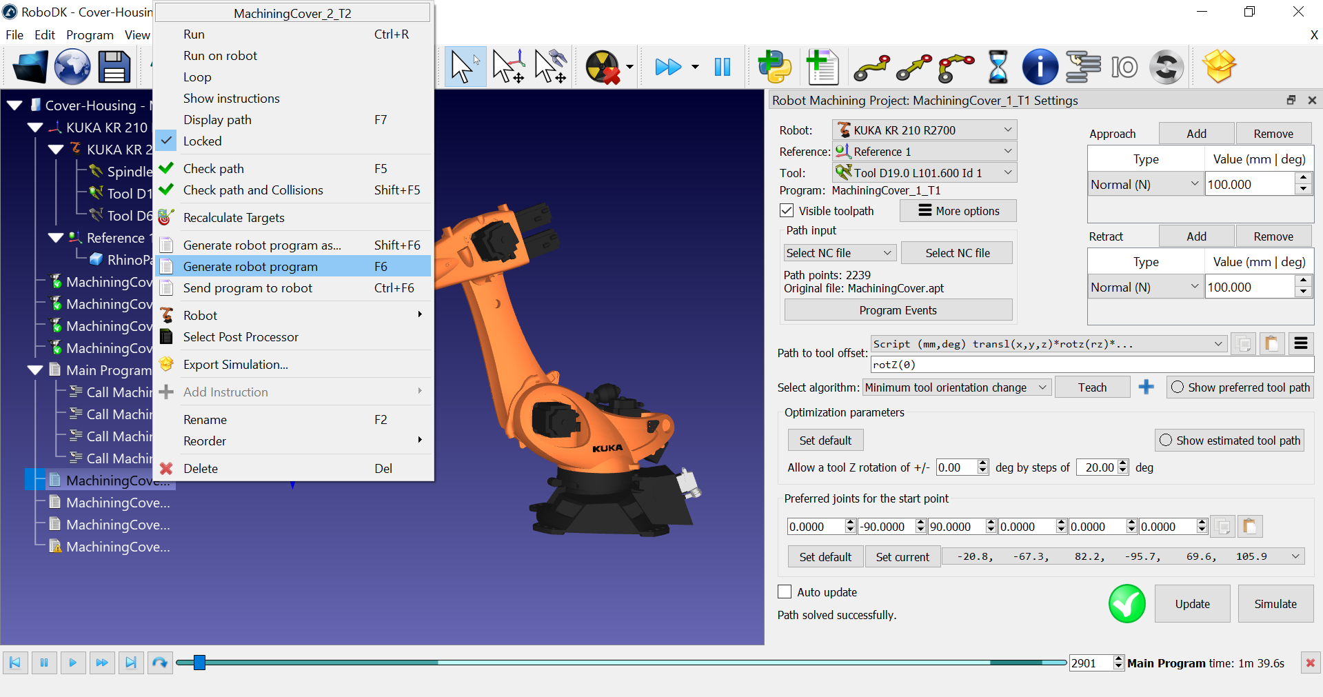
Generate the robot programs
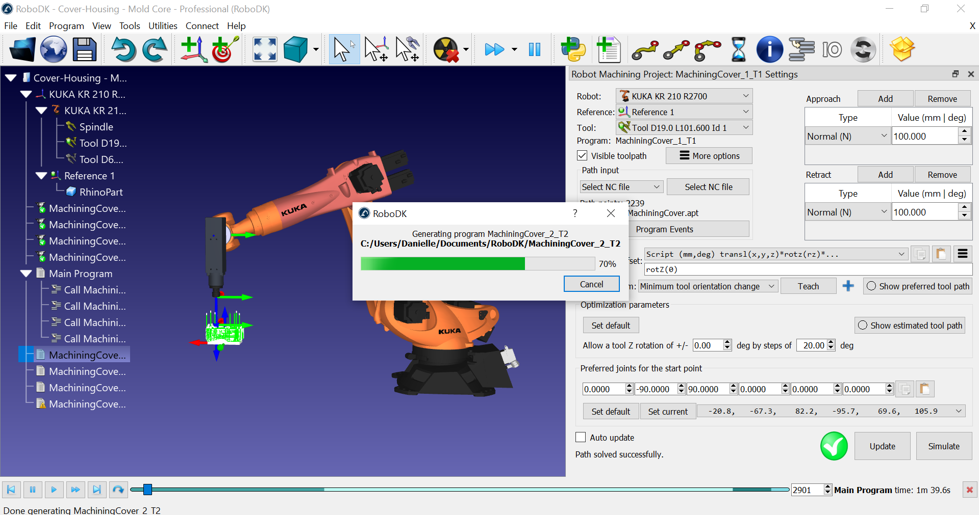
You can right click one or more programs and select Generate the robot programs to generate or update the robot programs (files) for your robot controller.
In this example, if we are using a KUKA KRC robot controller we’ll obtain SRC program files.
You should see the reference and the tool defined in the program the same way you defined them in RoboDK.
You can also use numbered reference and tool names to use the values stored in the controller given their ID.
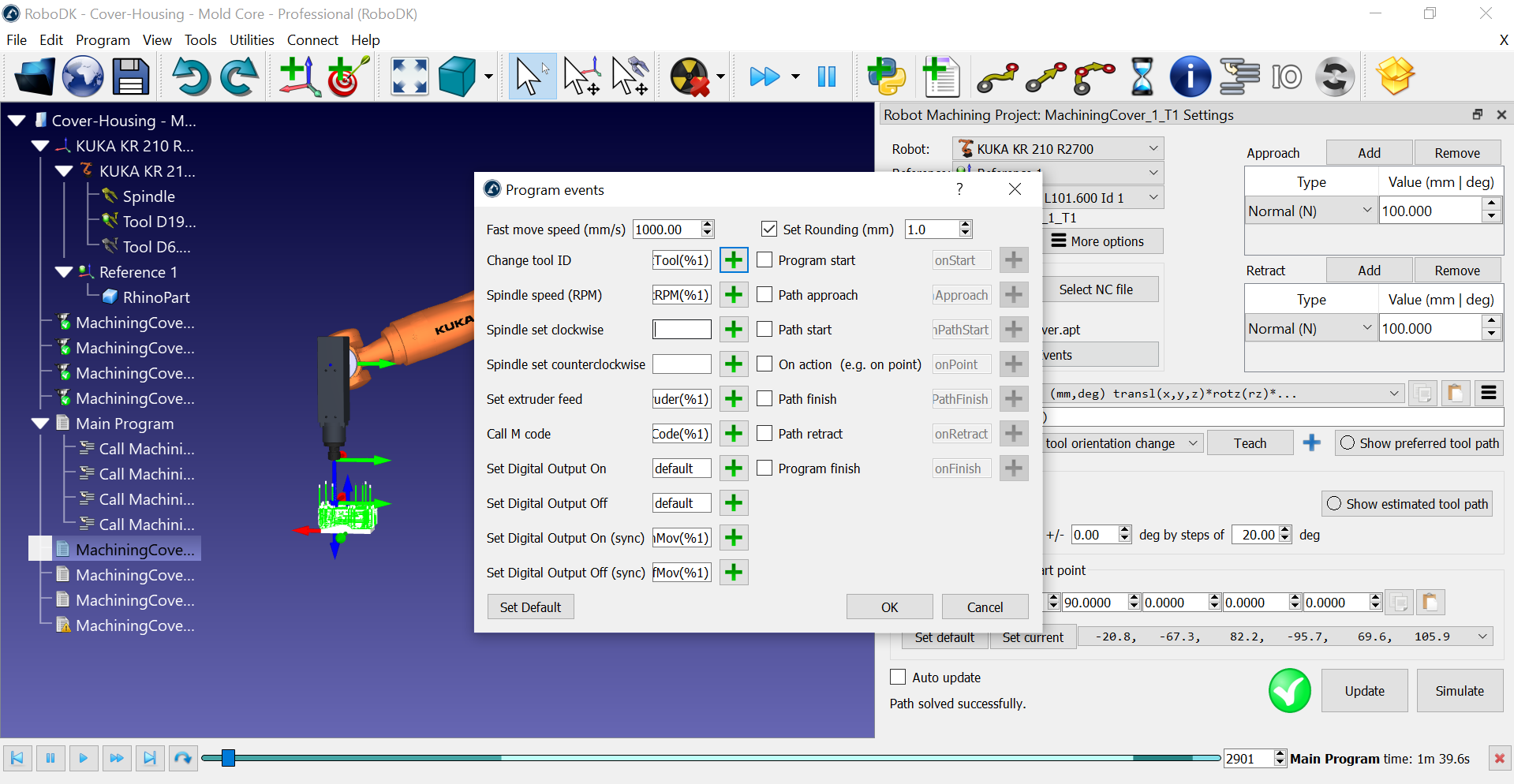
You can see custom program calls to select the correct tool according to your tool ID and activate the spindle. These settings can be customized in the Program Events menu. You can trigger a special procedure on your robot controller when a certain machining command must be executed, such as changing the tool, the spindle speed or running M codes.
Change the Post Processor
Each robot has a default post processor associated with it that should generate valid code for your robot controller. You can easily change the program output depending on the robot controller you use.
Follow these steps to change the post processor:
1.Right click on a program or a robot.
2.Select Select Post Processor to change the post processor.
This setting will apply to all programs using the same robot.
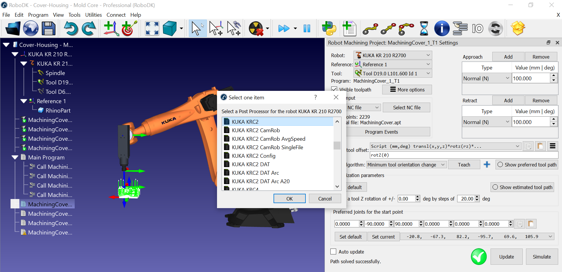
If you have a KUKA robot, you should see the KUKA KRC2 post processor selected by default. This should be compatible with KUKA KRC4 controllers as well. If you prefer, you can still select the KUKA KRC4 post processor if you have a KRC4 controller.