Dispensing
Introduction
This document will help you create a basic dispensing project in RoboDK for robot simulation and offline programming. In this example a Kawasaki RS007N robot is simulated and programmed for a robot liquid dispensing application using SolidWorks and RoboDK. You will learn how to transform a 2D sketch from SolidWorks into a real robot program in less than 15 minutes.
With the RoboDK plug-in for SolidWorks you can easily load 3D models created in SolidWorks to RoboDK. This plug-in allows you to program more than 50 different robot manufacturers and 500 robots directly from SolidWorks.
The RoboDK plug-in for SolidWorks works for SolidWorks 2016 and later and is free. However, certain options in RoboDK require purchasing a license.
Liquid dispensing example
To start the project, you will first have to select RoboDK’s liquid dispensing example in the default library.
Setup
This example uses the Kawasaki RS007N robot, a dispensing tool, the part, an oil pan and the jig to hold the part in place.
Load the station:
1.Select File➔ 
2.Locate the Liquid dispensing example fromRoboDK’s examples section:
C:/RoboDK/Examples/Plugin-SolidWorks-Liquid-Dispensing.rdk.
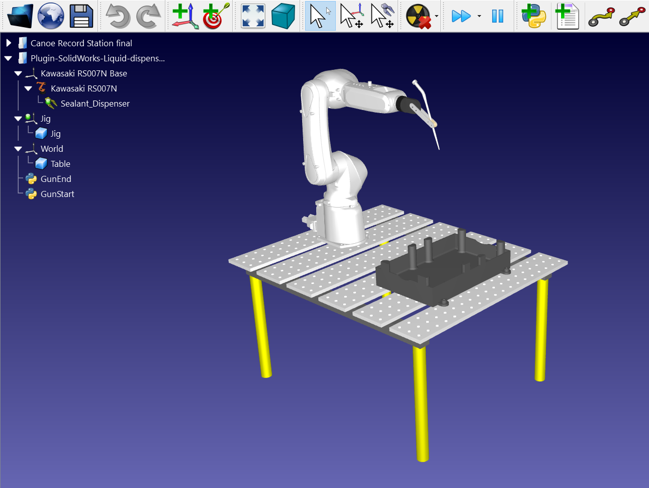
Now that you have loaded the station you can open SolidWorks.
2D sketch from SolidWorks
Open your 3D object in SolidWorks. In this example the 3D object is an oil pan with on top of it the groove that needs to be filled in.
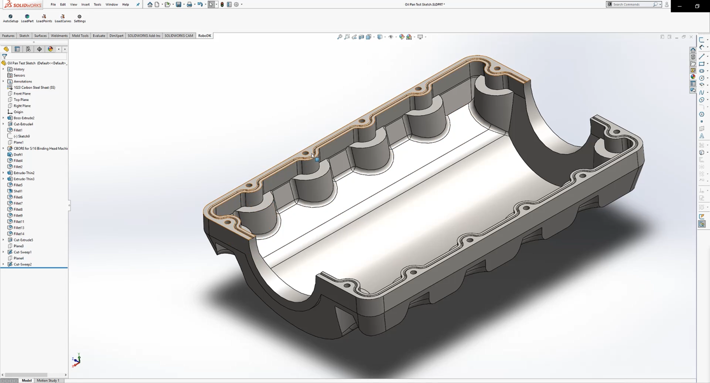
The goal of this project is to dispense sealants in the center of the groove at the top surface level without putting the sealant on either side. This way, the sealant can flow smoothly.
This is where the 2D sketch is used. You must start by creating a new sketch on top of the flat surface:
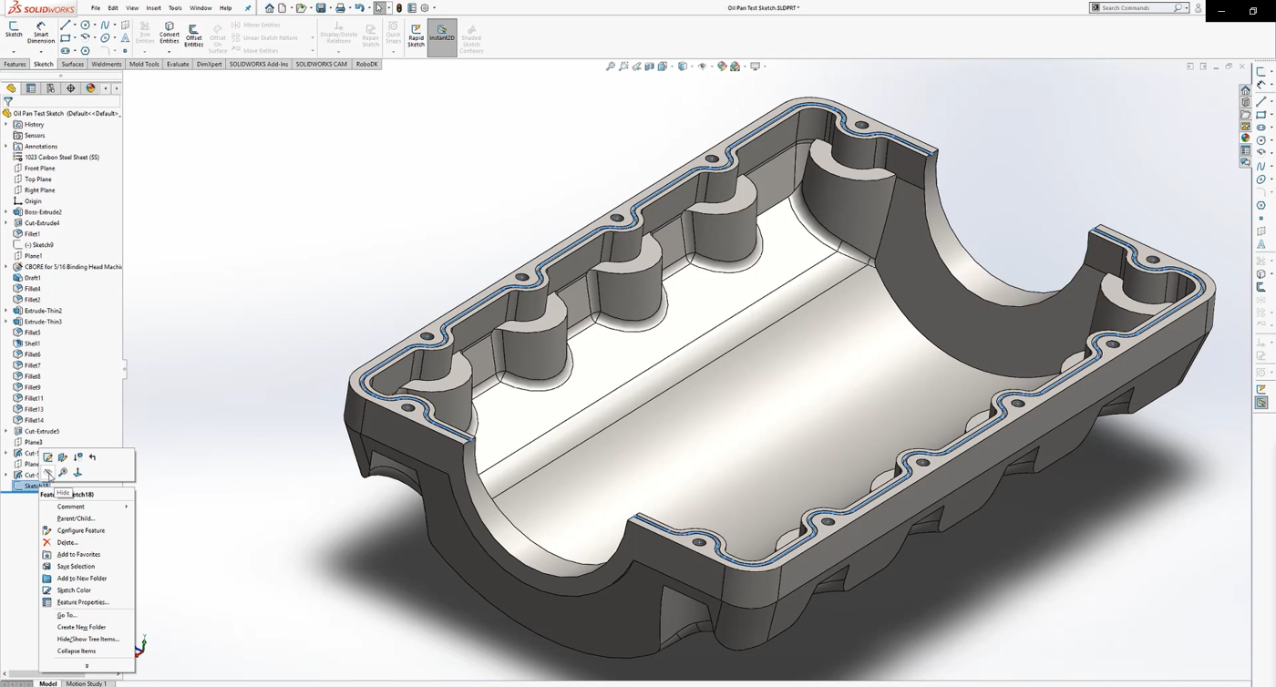
1.Select the Sketch tab and press on the Sketch button to create a new one
2.Select one of the edges of your 3D object
3.Right click on it and press Select Tangency to automatically select the entire edge of the groove
4.Select the Offset Entities button to enter the half width of the groove. In this case the value is 1,5mm.
You will have a complete tool path for your robot. Redo the same for the other side of the oil pan. Make sure that your sketch is visible as shown in the image below to be able to select it with RoboDK’s plugin.
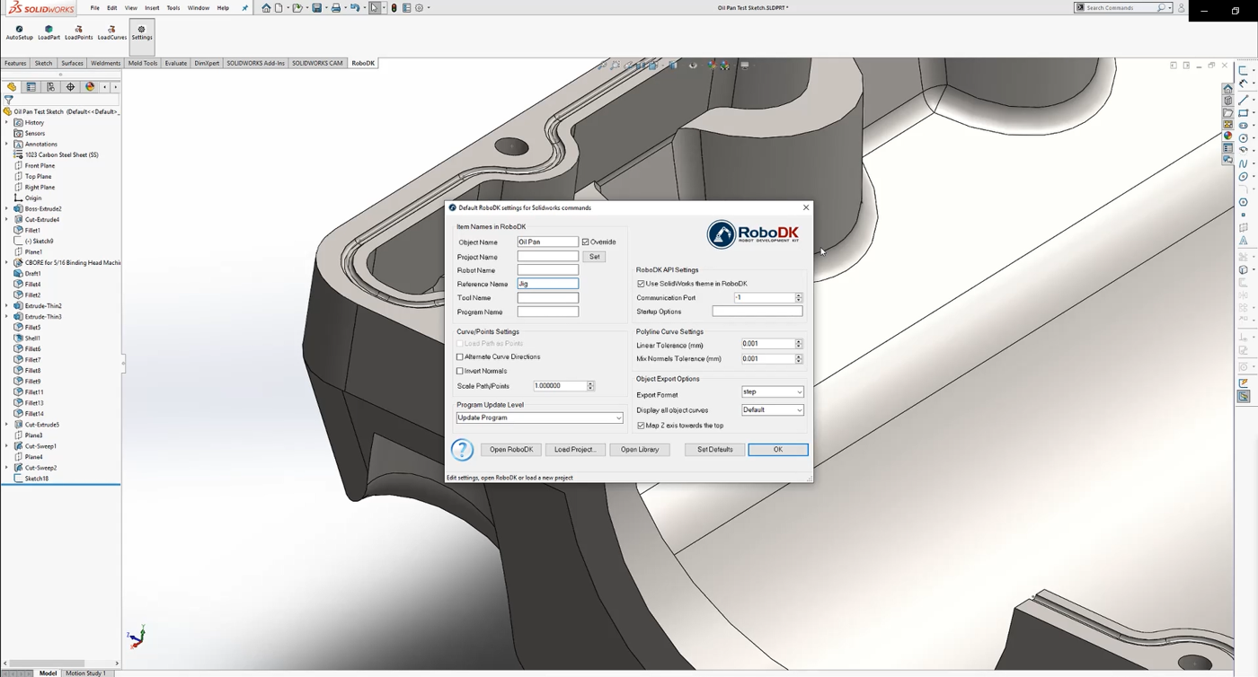
Follow the next steps to load your sketch into RoboDK:
1.Select the RoboDK tab and select 
2.Enter the Object Name you want in RoboDK. In this example it is Oil Pan.
3.Enter the Reference Name you want it to be exported in. In this example it is Jig.
4.Close the Settings window or select OK.
5.Select the 
6.Select all the lines and top surfaces of your sketch and press OK.
7.Select 
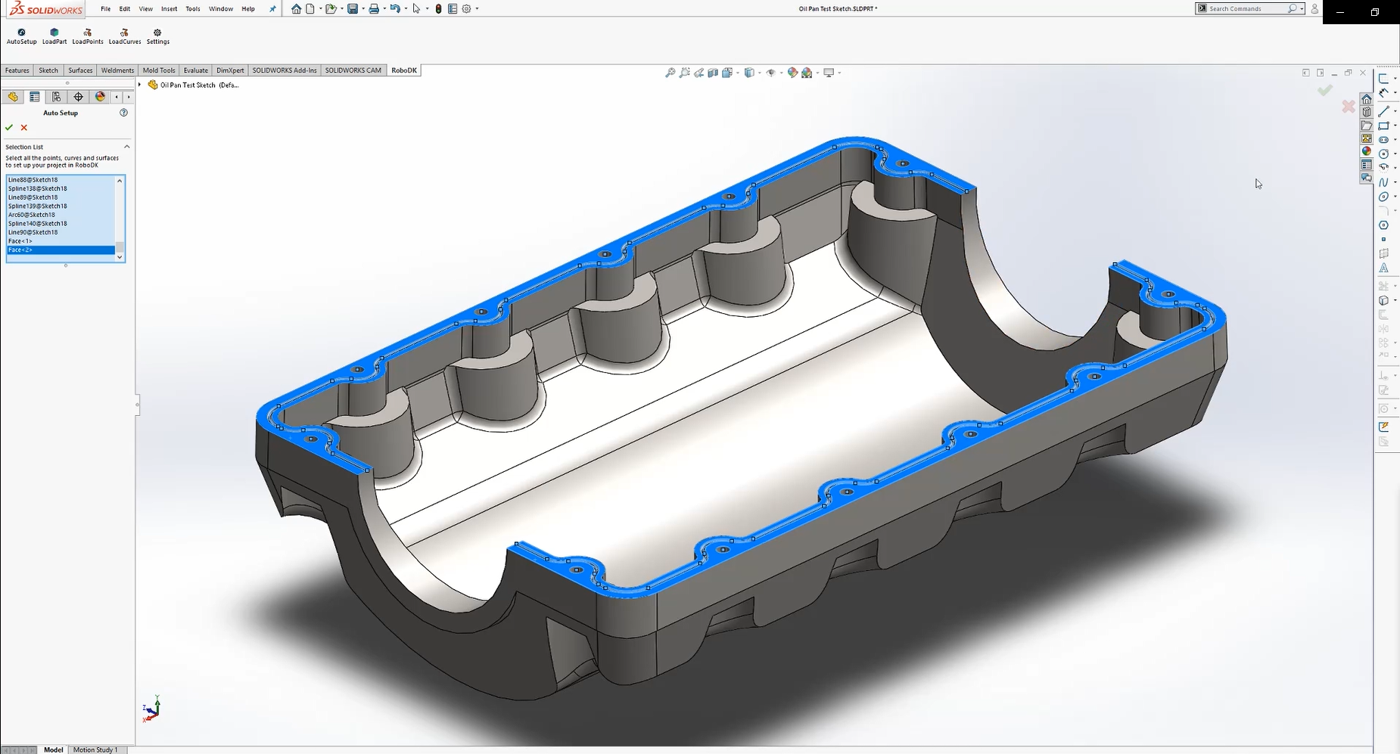
You should see the part loaded on the active reference frame (Jig) and a new Curve follow project in RoboDK that follows the toolpath.
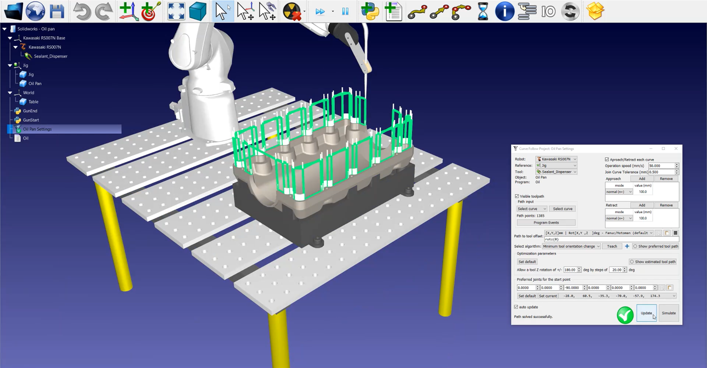
RoboDK station
The next step is to verify if the order in which the path sections will be executed is correct by selecting 
If you want to reorder or switch the sense of a path section, follow these steps:
1.Correct order of the path sections by clicking on
2.Right click an empty section of the station and Reset Selection.
3.Go to the starting point of your path and select the first section. Make sure that it is pointing in the right direction by right clicking on it and press Switch sense if needed.
4.Select Auto select next curve or Auto select all to automatically select every section of the path in the right order.
5.Select Done. This will bring you back to the RoboDK setting window.
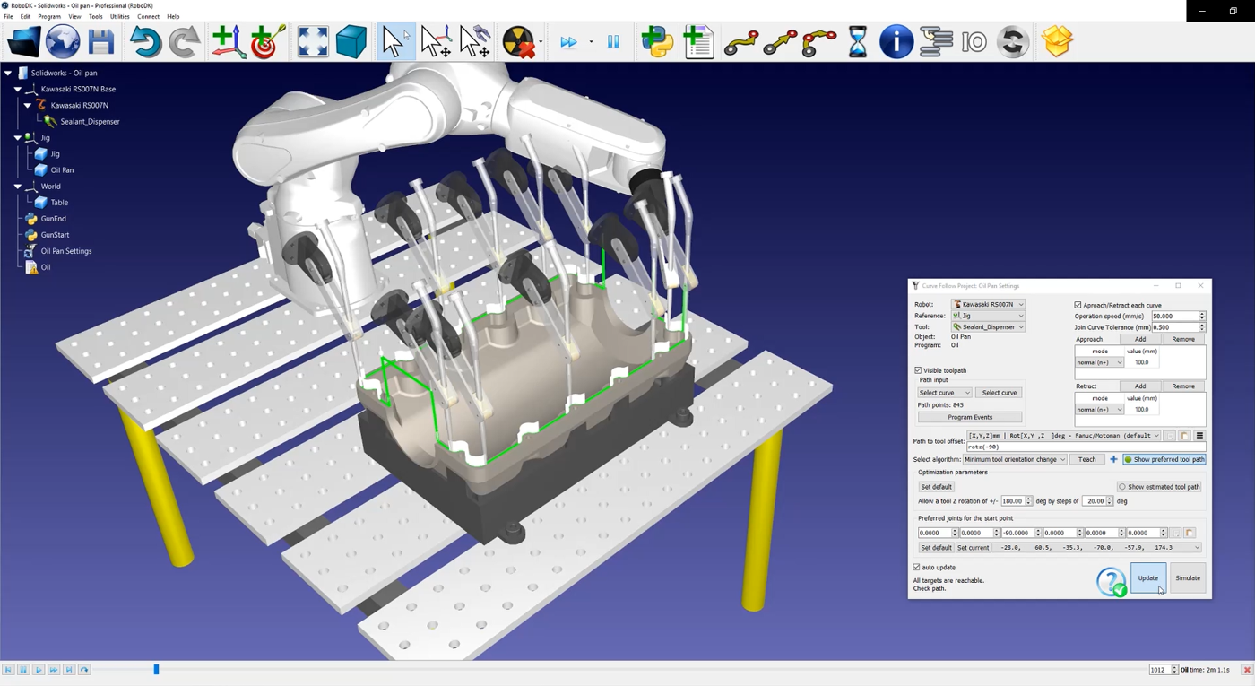
Next you will have to adjust the orientation of the tool:
1.Select Show preferred tool path to help visualize the tool along the path as shown in the image below.
2.Modify the rotz value. In this example -90 degrees is set up.
3.Select Update ➔ Simulate.
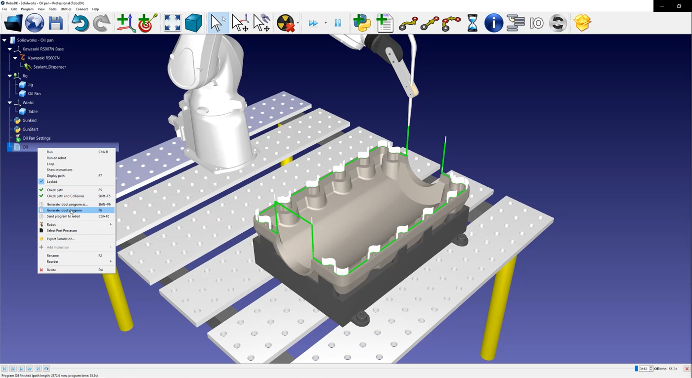
To generate your robot program right click on 
The .pg file is now ready to be transferred to your robot controller.