Laser Cutting
Introduction
This section will help you create a basic project in RoboDK for robot simulation and offline programming. In this example a Motoman robot is simulated and programmed for a laser cutting application using Fusion 360 and RoboDK.
You can choose between two different methods: One using the feature extraction method and one using the laser cutting features from Fusion 360.
With the RoboDK plug-in for Fusion 360 you can easily load 3D models created in Fusion 360 to RoboDK. This plug-in allows you to program more than 50 different robot manufacturers and 500 robots directly from Autodesk Fusion 360.
The RoboDK plug-in for Fusion 360 is free if you have a RoboDK license.
Laser cutting example
To start the project, you will first have to select RoboDK’s laser cutting example in the default library.
Setup
This example uses the Motoman MH50-35 robot, a laser cutting head, a stamped piece of metal and a laser cutting table.
Load the station:
1.Select File➔
2.Locate the Laser-Cutting example from RoboDK’s examples section:
C:/RoboDK/Examples/Plugin-Fusion-360-Laser-Cutting.rdk.
Note that the 
Now that you have loaded the station you can open Fusion 360.
Method 1: Feature extraction
Open your 3D object in Fusion 360. In this example the 3D object is a stamped piece of metal.
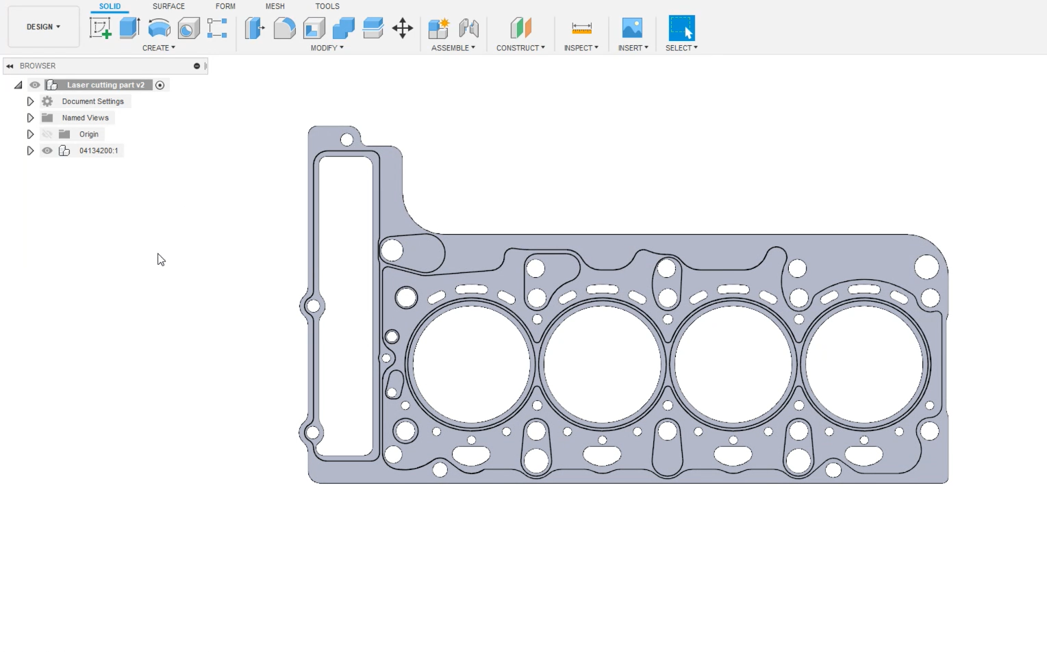
The goal of this project is to automatically create a robot program that will cut all those holes with a leaser cutter. Programming that by hand would take too long.
1.Select the Design section of Fusion in the top left-hand corner.
2.Select the Tools tab. This is where you will find the RoboDK plugin.
3.Click on the button 
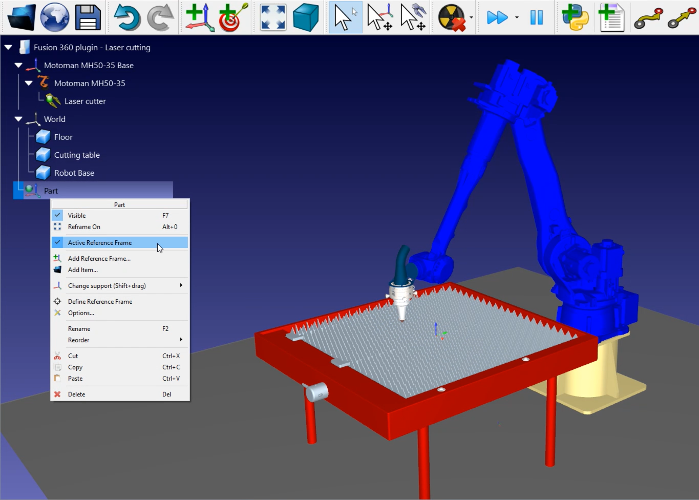
The part has been imported in the active reference frame of your RoboDK station. Make sure that the part has been imported in the right orientation. In this example, you will have to modify the orientation of the part.
Follow the next steps to modify the orientation of your part:
1.Double click the
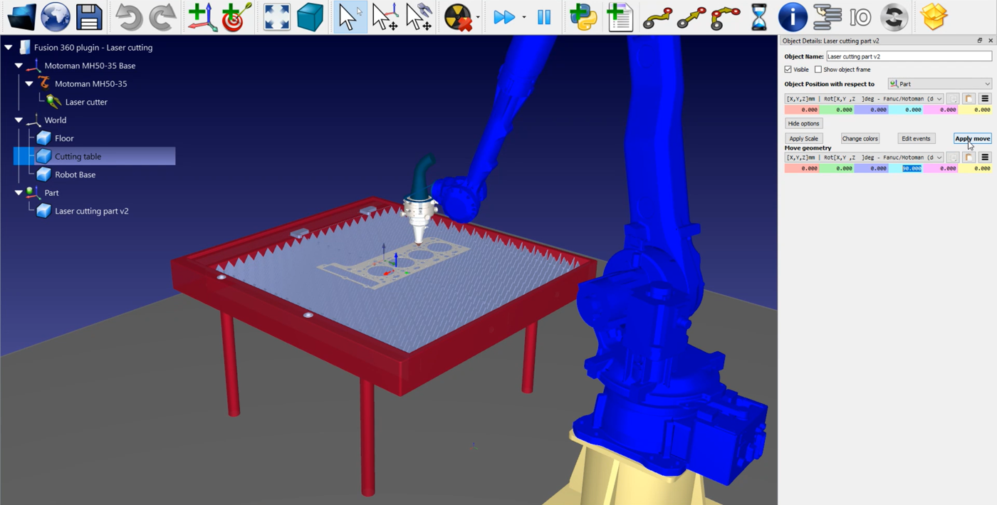
2.Click on More options in the open menu.
3.Go to Move geometry and enter 90 in the X axis (light blue) as shown in the image above.
4.Click on Apply Move to save the orientation.
The RoboDK plugin has another feature in Fusion 360 that will help you import your cutting path to RoboDK.
1.Go back to Fusion 360.
2.In the RoboDK plugin menu, select Load Curve(s).
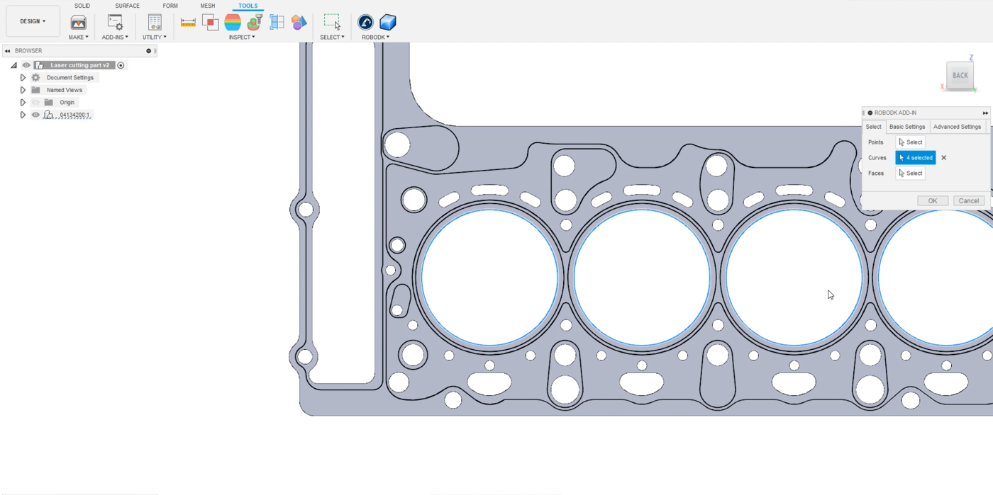
3.Select Curves in the open menu.
4.Select the edges of the four big circles as shown in the image below.
Now you will need to give RoboDK an orientation for the robot tool.
1.Select Faces in the open menu.
2.Select the faces you wish the tool to be normal to as shown in the image below.
Now you can configurate the settings:
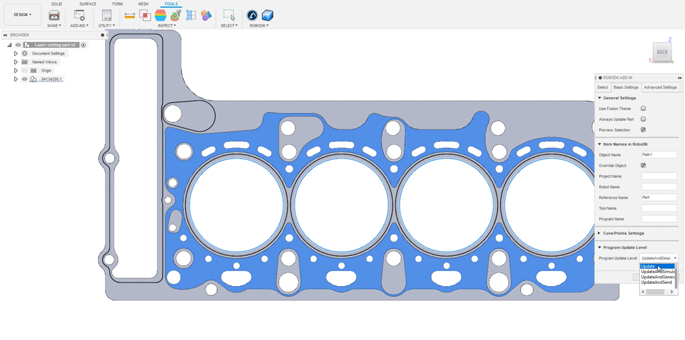
1.In the same menu, go to Basic Settings.
2.Uncheck the Use Fusion Theme if you prefer to keep RoboDK in its default behavior.
3.Enter an Object Name to name your path. In this example it will be Path 1.
4.Enter a Reference Name you want it to be exported in. In this example it is named Part, the same as in the RoboDK station.
5.Select Update in the Program Update Level to have more options afterwards as shown in the image above. This is optional.
6.Click on OK.
You should now be able to see the imported path in RoboDK. In this example, the orientation is wrong again and you will need to modify the orientation as you did for the part before.
1.Double click your path, in this example it is
2.Click on More options in the open menu.
3.Go to Move geometry and enter 90 in the X axis (light blue).
4.Click on Apply Move to save the orientation.
The next step is to verify if the order in which the path sections will be executed is correct by selecting 
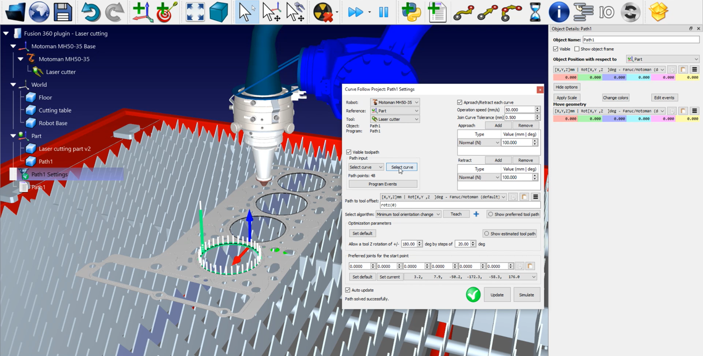
1.Double click on your path settings, here
2.Make sure the that the robot, the reference, and the tool are the right ones.
3.Click on Select curve.
4.Select the other circles.
5.Click 
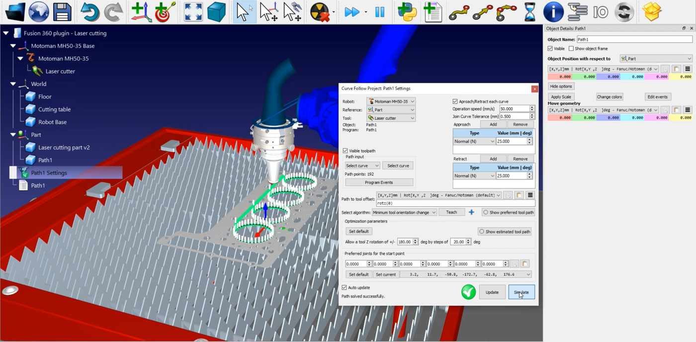
You can now notice that the approach and retract movements are a bit too long in terms of length.
You can easily modify those values by:
1.Double click on your path settings, here
2.Enter a smaller value in the Approach and Retract boxes. In this example, you can enter 25mm.
3.Click on Update➔Simulate.
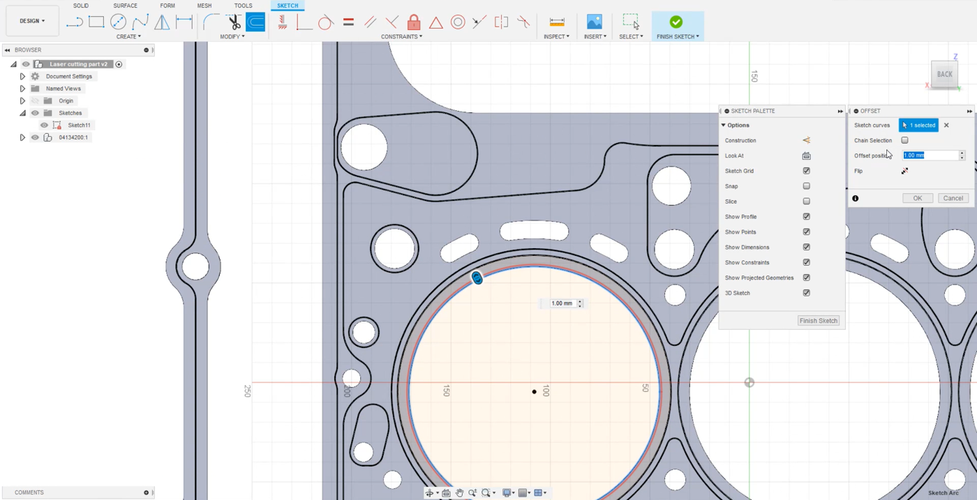
The next step is to consider the radius of the laser. In this example, the laser is cutting too much material.
How to set up your laser radius:
1.Go back to Fusion 360.
2.Got to the tab Solid➔Create Sketch to create your sketch.
3.Select one circle and click on Offset in the top menu to create a new path.
4.Considering that the diameter of the laser beam is 2mm, the radius will be 1mm. Enter 1 in the Offset position box as shown in the image below.
5.Repeat those steps for the 3 other circles.
6.Click Ok.
You can now load the curves into RoboDK.
1.Go to the Tools tab.
2.Click on RoboDK➔Load Curve(s).
3.Select Curves and click on the sketch in each circle.
4.Select Faces and click on the face you wish the tool to be normal.
5.In this example, the Object Name (Basic Settings) is Path2.
6.Click Ok to import the path into RoboDK.
You can modify the orientation of Path2 as explained above. If you come closer, you can see the difference between the two paths. You can now delete the Path1.
The next step is to verify if the path sections you loaded are correct by:
1.Selecting
2.Click on Select curve and select the other circles as shown in the image below.
3.Select
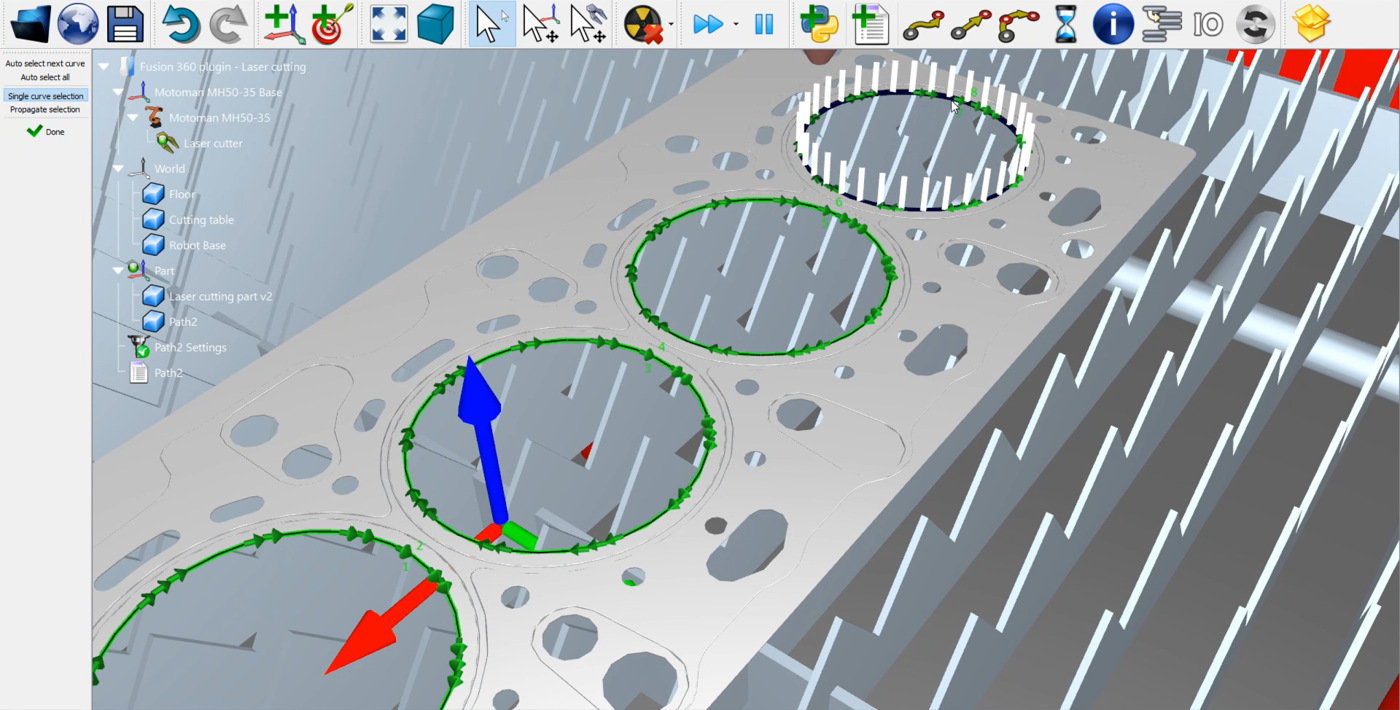
You can reduce the size oh the Approach and Retract movements as explained above. In this example, you can enter again 25mm. Don’t forget to Update➔Simulate your Curve Follow Project to save your settings. You could do the same steps for all other holes of this part.
This way of building a laser cutting program works for RoboDK’s Fusion 360 plugin, but it also works for all the CAD plugins.
Method 2: Fusion 360 laser cutting features
To use the Fusion 360 laser cutting features, go back to Fusion and hide the sketches you did before as shown in the image below.
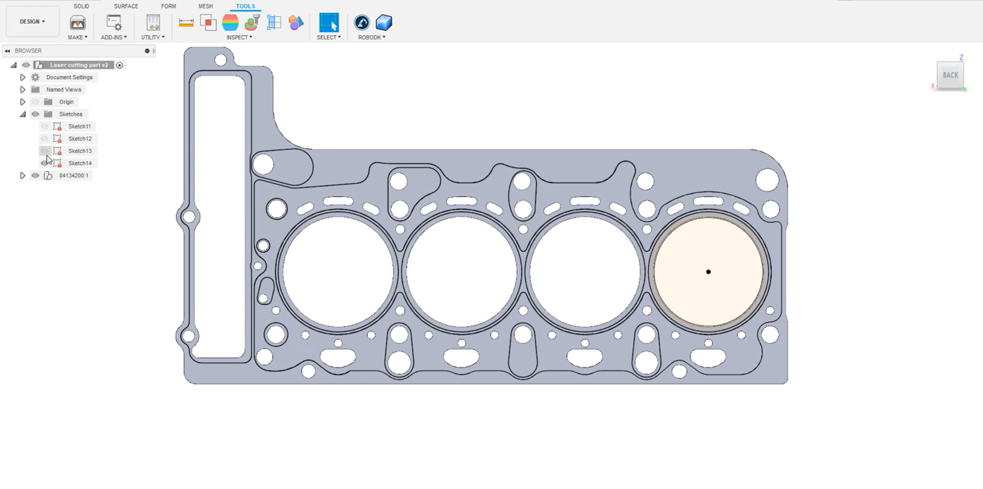
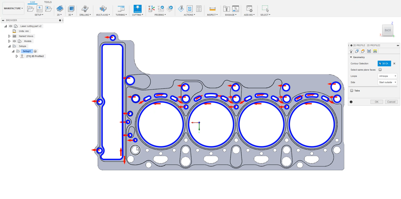
Switch from the Design section in the top left-hand menu to Manufacture. In the tool bar click on the 2D cutting feature.
1.Select a Tool. In this example it is a 1 mm wide cutter.
2.Go to the Geometry tab in the same menu and select the circles you want to cut. In this example, all holes of the stamped piece of metal are selected as shown in the image below.
3.Click OK.
You can simulate the path in Fusion 360 by right clicking on your path and selecting Simulate. In the Setup, make sure that you are using the same origin as the model. This way, it will be exported at the right position.
1.Right click on Setup1➔Edit.
2.Make sure that Model origin is selected in the Origin box.
3.Select Ok.
Now you can transfer your sketch to RoboDK by selecting Tools➔Load CAM project in RoboDK in the Fusion 360 tab.
You should see the imported sketch in RoboDK. Make sure to delete the previous path, in this example Path2. Double click on 
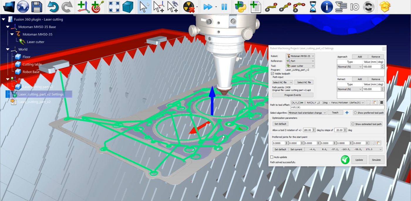
The only thing to manage is the Program Events:
1.Click on Program Events.
2.Let the first three text boxes free as you are not doing a machining project with a spindle, multiple tools, or some specific RPM to reach.
3.Check the Path start box and write LaserOn to activate the laser only when the path starts
4.Check the Path finish box and write LaserOff to deactivate when the path ends.
5.Click Ok and Update.
To generate your robot program right click on 
The .pg file is now ready to be transferred to your robot controller.