Deburring
Introduction
Robotic plastic deburring consists of a robot arm removing excess material from plastic molded parts. This example will help you create a project in RoboDK for robot simulation and offline programming. This example also shows how you can use the Fusion 360 plugin to generate toolpaths in RoboDK.
With the RoboDK plug-in for Fusion 360, you can easily create a machining project and automatically export the generated path inside RoboDK. RoboDK will then transform it into a robot program. you can easily load 3D models created in SolidWorks to RoboDK. The RoboDK Add-In allows you to program any robot arm directly from Fusion 360 for any manufacturing application.
Plastic deburring example
To start the project, you will first have to select RoboDK’s plastic deburring example from the default library.
Setup
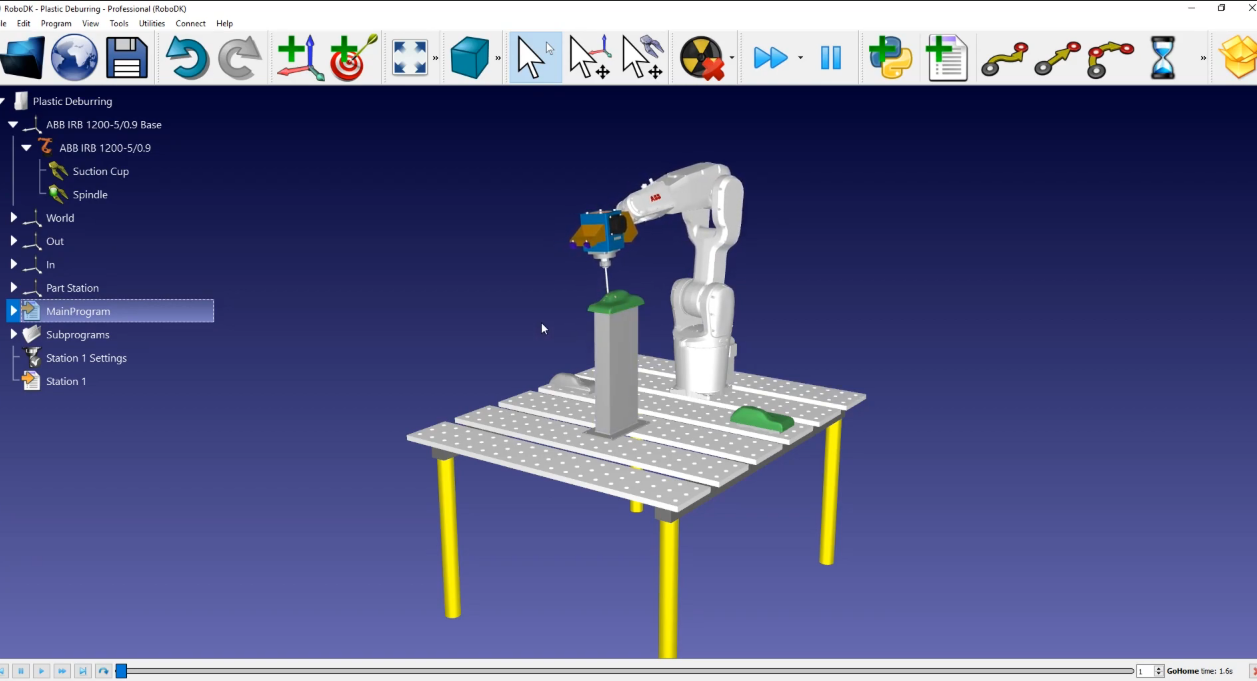
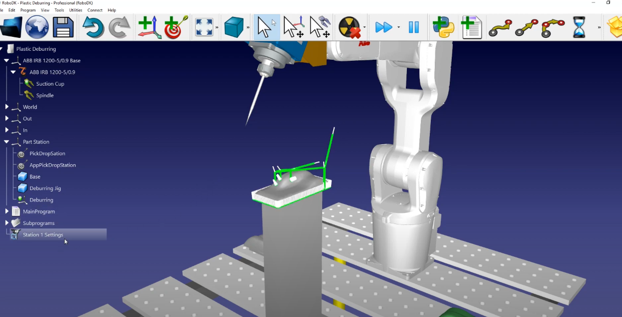
This example uses a simple setup: A robot mounted on a table (this example includes an ABB robot), a pile for the freshly molded part, a pile for the processed one, and the jig in the middle to hold the part in place.
Load the station:
1.Select File➔ 
2.Locate the Plastic Deburring example fromRoboDK’s examples section:
C:/RoboDK/Examples/Plugin-Fusion360-Plastic-Deburring.rdk.
Now that you have loaded the station you can open Fusion 360.
2D sketch from Fusion 360
Open your object in Fusion 360. In this example the object is a plastic part. The goal of this project is to remove excess material in the three holes, and all around the part near the bottom of it.
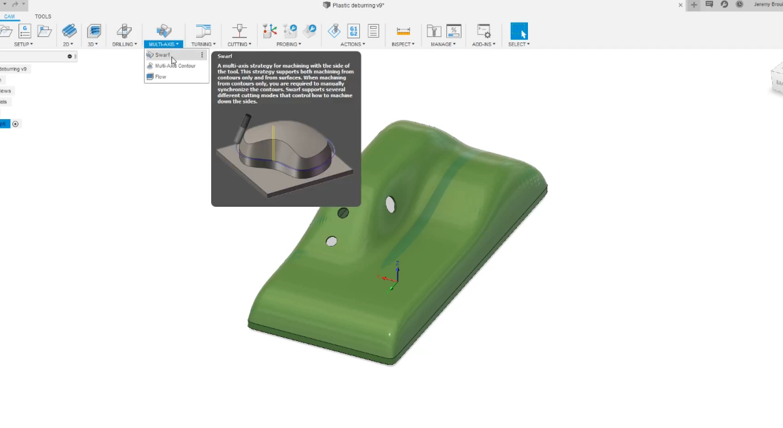
First, you need to make sure that you are in the “Manufacturing” workspace tab of Fusion. We should follow these steps to create the tool path:
1.Select Multi-Axis and then select the Swarf tool.
2.Select the tool you wish to use (in this example we will be using a custom tool from our RoboDK station) and then select the hole to create the first path.
3.To get the tool path on the right side of the surface, we will select Machine Other Side and then select Ok. Follow this procedure for each hole.
4.To do the same thing to the bottom part, you will select the Swarf tool and then select the bottom part.
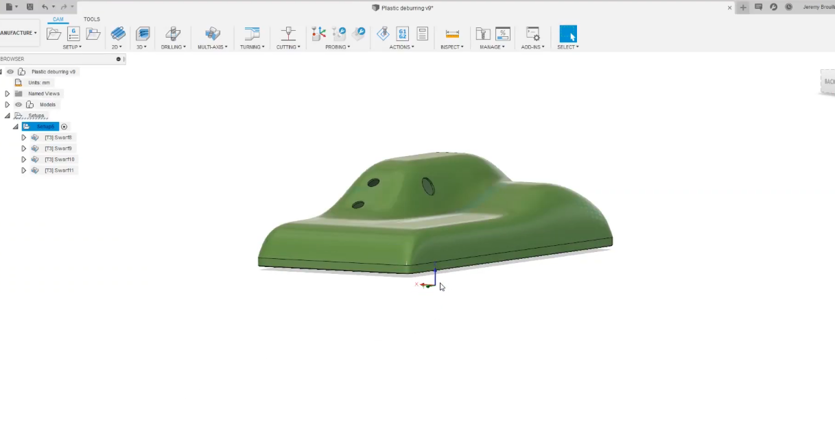
5.Once the calculation is done, we will simulate the paths we just created: Select your Setup and then select Simulate.
You will have a complete tool path for your robot. We will need to go back into RoboDK to make sure that the “Deburring” reference frame is activated. To do that we must:
Go into RoboDK: select Deburring and then select Activate Reference Frame.
Now that the Deburring reference frame is activated, the program will be exported with respect to that reference frame. e will go back into Fusion 360 and verify that the image is as shown:
Follow these steps to load your sketch into RoboDK:
1.In Fusion 360, you have the RoboDK plugin. Simply select Load CAM project in RoboDK
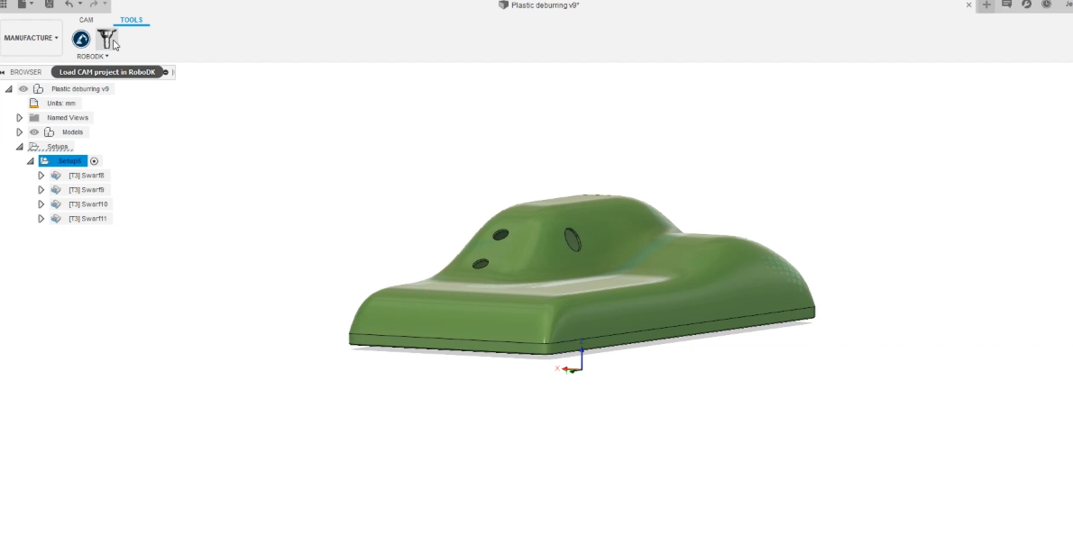
2.If we go back to RoboDK, we can find the cutting path at its place. A “Machining Project” called “Plastic Deburring” was created: Select Deburring and then select Visible.
3.We can rename the cutting toolpath to “Station1 Settings”: Right-Click on Plastic Deburring to rename it.
RoboDK station
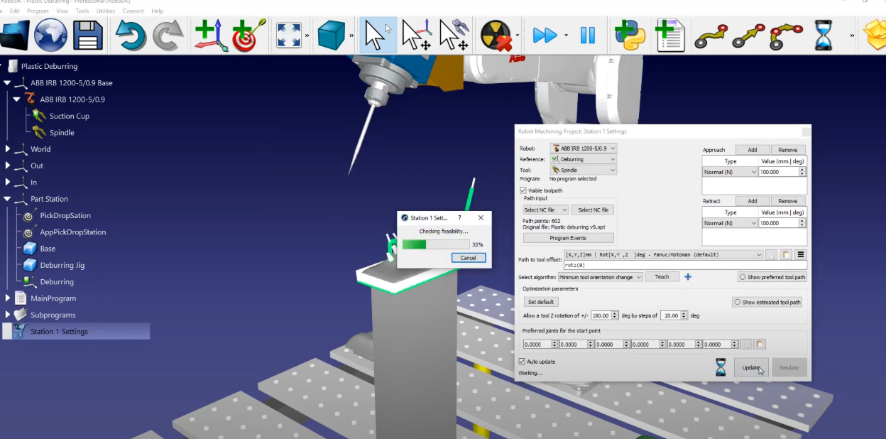
Once we have the robot toolpath ready in RoboDK we should make sure the virtual robot cell matches the real setup. In RoboDK we make sure we are using the correct tool and reference frame for the manufacturing operation before we generate the robot program.
In this example we selected the reference Deburring and the tool as Spindle. Select Update ➔ Simulate.
If you want to reorder or switch the sense of a path section, follow these steps:
1.CAM projects usually already come with their approach and retract movements, so we can remove ours: Simply go to “Approach” and “Retract” and select Remove. Select Update and then Simulate.
2.In this example, the default parameters produce a valid result. The only additional setting we may want to change is to activate and deactivate the spindle: Open Program Events ➔ Add a subroutine in “Path Approach” and “Path Retract” by checking off each option and write “Spindle (1)” in Path Approach and “Spindle (0)” in Path Retract. This assumes you have a function defined in the controller than can accept a parameter to activate or deactivate the spindle.
3.Select Update.
Now we must modify the name of the program that we created “Station 1” and launch the “Main Program”
The last thing we need to do is to generate the robot program. Since we are using an ABB robot, we’ll need to export a mod file for the ABB robot controller that uses ABB’s proprietary RAPID programming language.
1.Make sure that we use the correct post processor: Select Station➔ Select Post Processor➔ ABB RAPID IRC 5.
2.Right-Click on the Station1 program and select Generate Robot Program.
You should automatically see the robot program in a text editor. You will be able to see all of the specific move commands and syntax required by the ABB robot controller.