Polishing
Introduction
This example will help you create a basic polishing project in RoboDK for robot simulation and offline programming. In this example a KUKA robot is simulated and programmed for a robot sanding or polishing application using Inventor and RoboDK. You will learn how to generate a real robot path on a curved surface by creating a 3D sketch in Inventor and importing it to RoboDK.
With the RoboDK plug-in for Autodesk Inventor you can easily load 3D models created in Inventor to RoboDK. This plug-in allows you to program more than 50 different robot manufacturers and 500 robots directly from Inventor.
The RoboDK Add-In for Autodesk Inventor works with Inventor 2018 and later. The RoboDK Inventor Add-In is free if you already have a RoboDK license.
Polishing example
This section will show you how you can use a KUKA robot for polishing.
Setup
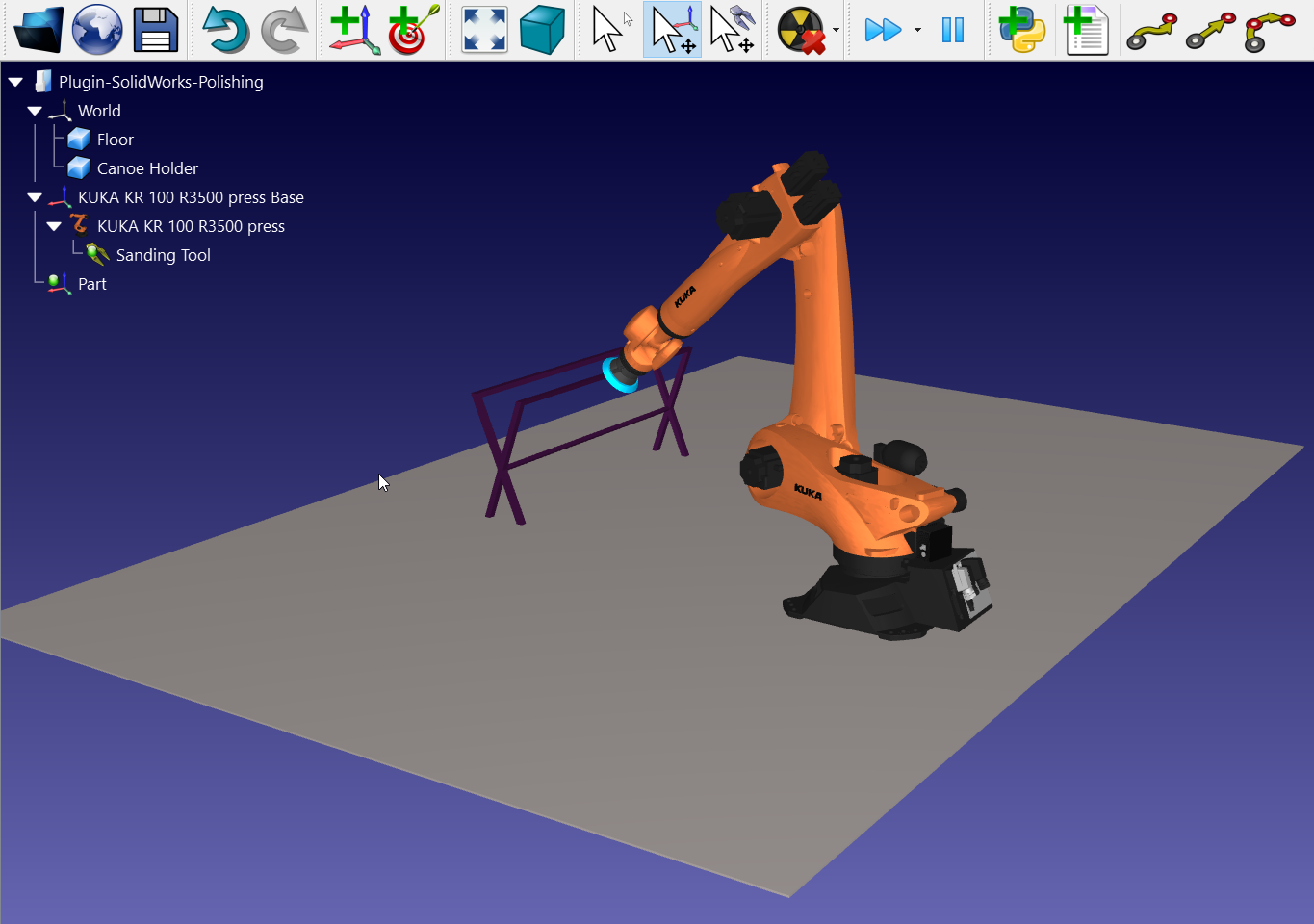
To start the project, you will first have to select RoboDK’s polishing example in the default library.
The example includes a KUKA robot, a rotative polishing tool, the part (canoe) and a metallic stand on which the canoe rest.
Open the project:
1.Select File➔ 
2.Locate the Polishing example from RoboDK’s examples section:
C:/RoboDK/Examples/Plugin-Inventor-Polishing.rdk.
Now that you have loaded the station you can open Inventor.
3D sketch from Inventor
Open your 3D object in Inventor. In this example the 3D object is a canoe with a curved exterior surface that needs to be polished.
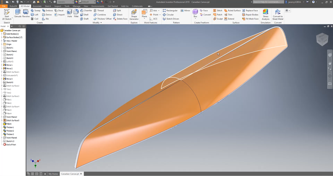
The goal of this project is to create and import a polishing path on a curved surface. The path will be an up and down movement to polish the first section of the part.
You will have to create a plane at a 45-degree angle to draw a path on that flat plane and then use the curve projection tool to project the path on the curved surface.
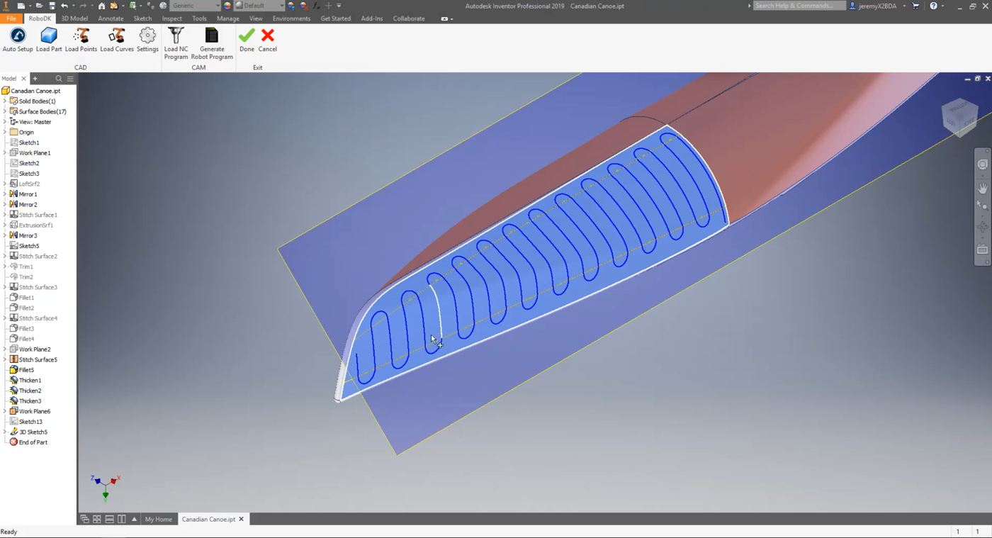
In this example, RoboDK already drew the path. You can make it visible by right clicking on Sketch13➔Visibility on the left-hand side menu as shown in the image below.
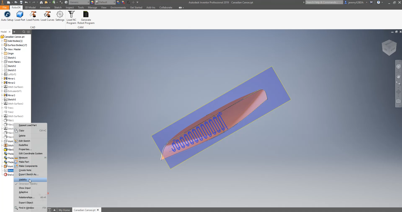
As you can see, the path covers all the first selected section. You can reopen the sketch and modify the path if need by right clicking on Sketch13➔Edit Sketch.
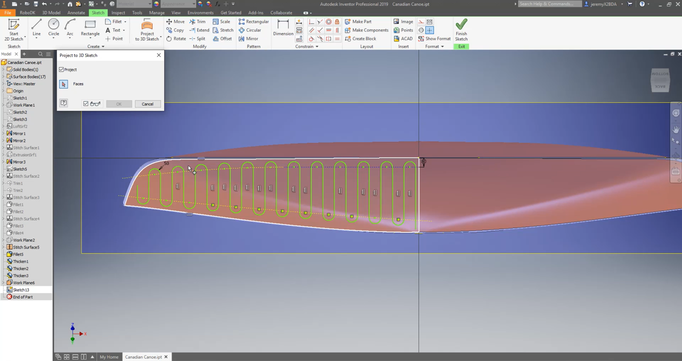
Now it is simple to project that path on the surface using the Inventor tool:
1.Select the Sketch tab in Inventor and select Project to 3D Sketch.
2.Select the surface that you want the path to be projected on.
3.Select OK and Finish Sketch.
As soon as you accept those modifications, a 3D sketch will be created.
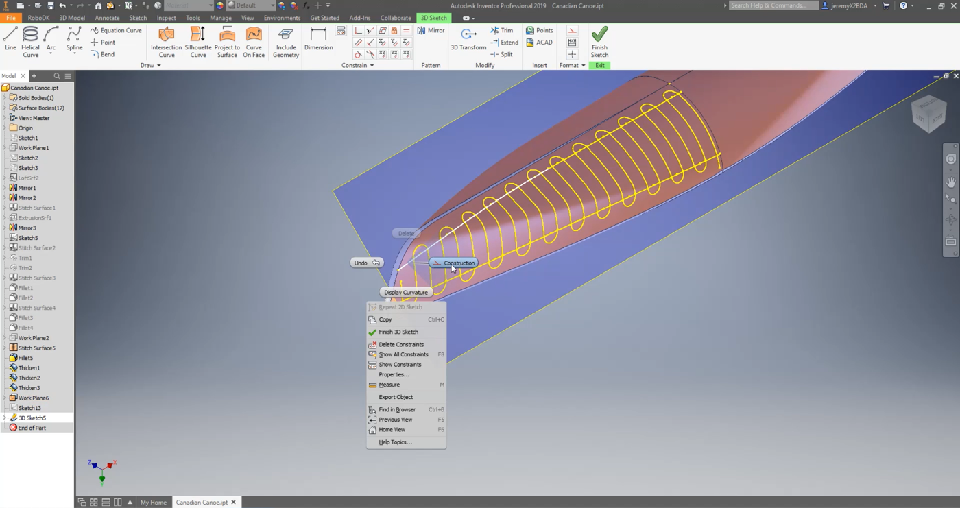
Make sure the created construction lines are properly defined as construction lines:
1.Right click on Sketch13➔Visibility to make the path visible.
2.Right click on Sketch13➔ Edit 3D Sketch
3.Select the line you want to check on your 3D model.
4.Select Construction.
5.Select Finish Sketch.
Follow the next steps to load your sketch into RoboDK:
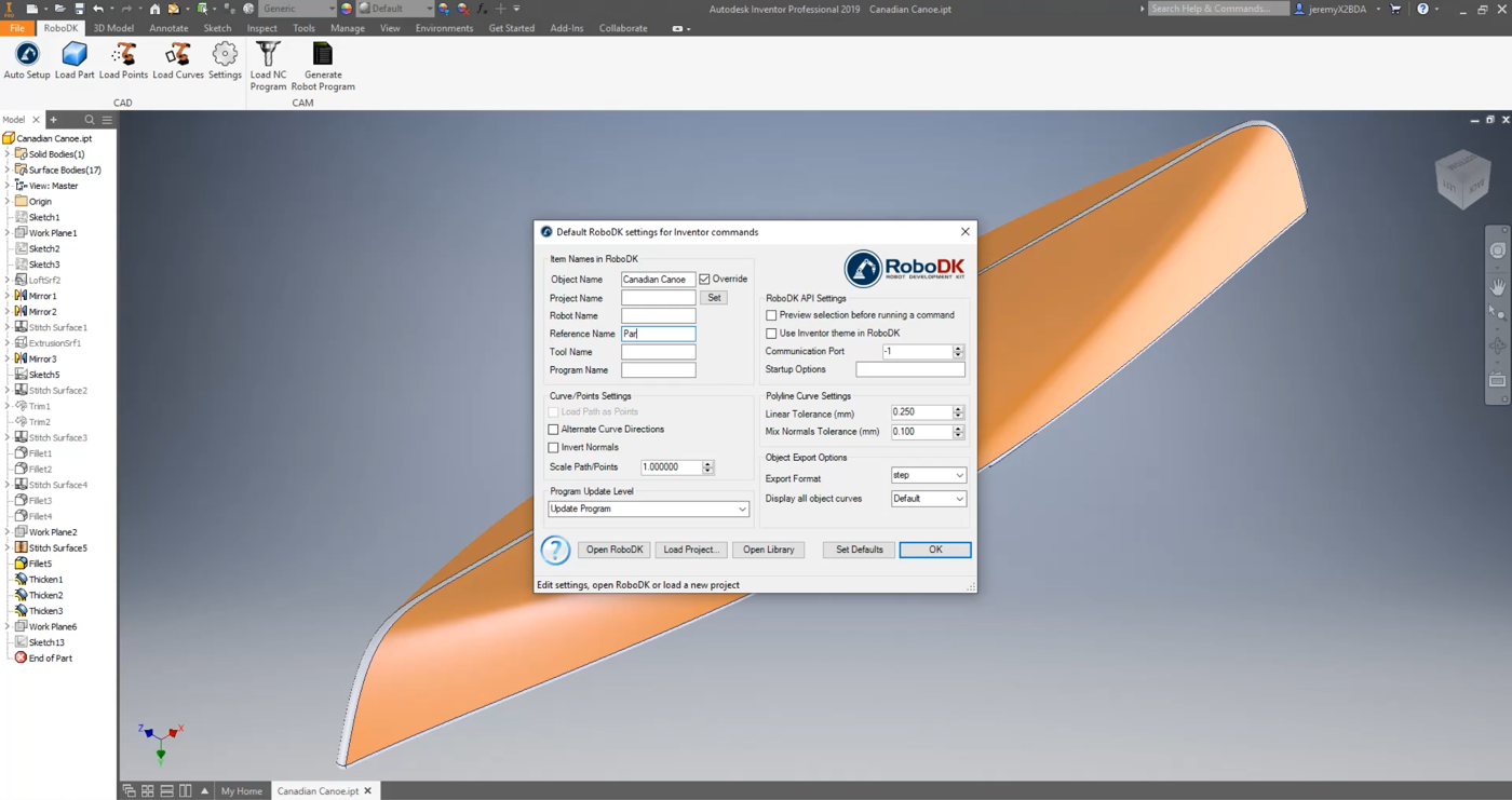
1.Select the RoboDK tab in Inventor and select 
2.Enter the Object Name. In this case it is Canadian Canoe.
3.Enter the Reference Name where you want your part to be imported. In this example it is Part. If you do not provide any reference name, the activated reference frame will be used. If there is no activated reference frame, a new one will be automatically created.
4.Close the Settings window or select OK.
5.Select the 
6.Select all the lines and the top surfaces of your sketch and press OK. This step is essential as it will give RoboDK the needed information to calculate the normal to the surface and therefore calculate the orientation of the polishing tool on the curved surface.
7.Select 
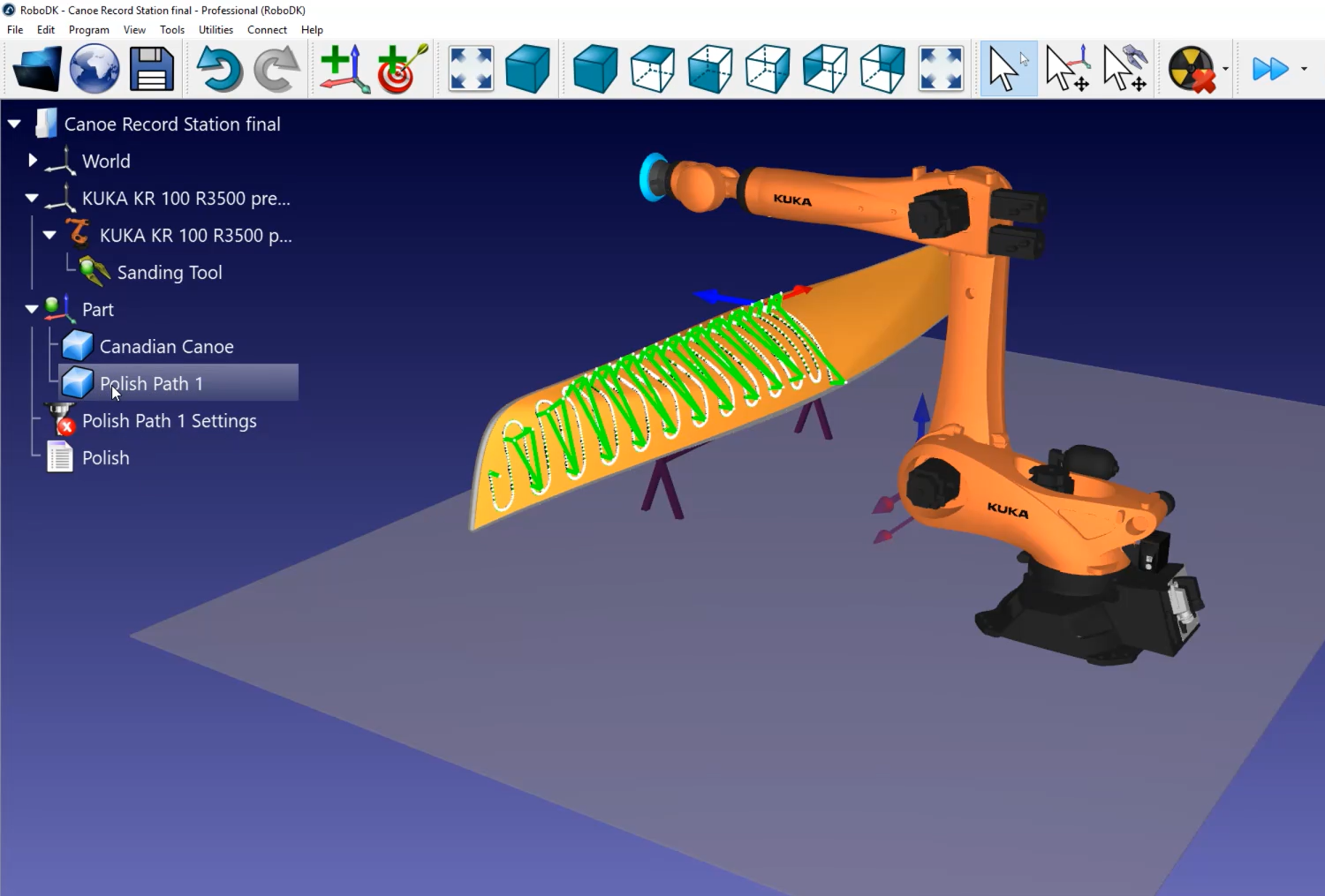
You should see the part (Canadian Canoe) and the path (Polish Path 1) loaded in RoboDK on the active reference frame (Part).
RoboDK station
The next step is to verify if the order in which the path sections will be executed is correct by selecting 
You can see the little white lines coming out of the path on the canoe. Those are the normals to the surface. In this example all seem to have been correctly imported.
Follow these steps to set up the direction of the path:
1.Select
2.Click on Select curve.
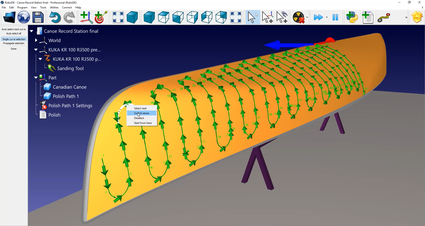
Now you can see the order and direction in which the path segments are executed. If you want to change direction, right click on it, and select Switch sense.
In this case, the path needs to be redone:
1.Right click on an empty space of the station (i.e. blue background).
2.Select Reset selection.
3.Select the line you want to start with. Make sure that it is pointing in the right direction.
4.Select the Auto select all tool on the top left-hand corner of your screen.
5.Select Done.
You can now simulate your station by double clicking on
You can also add normal movements of 200 millimeters to help avoid collision between the robot and the canoe by double clicking on
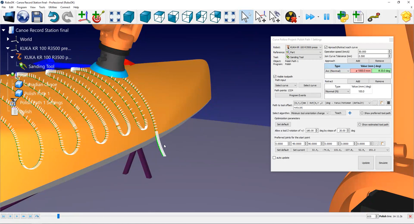
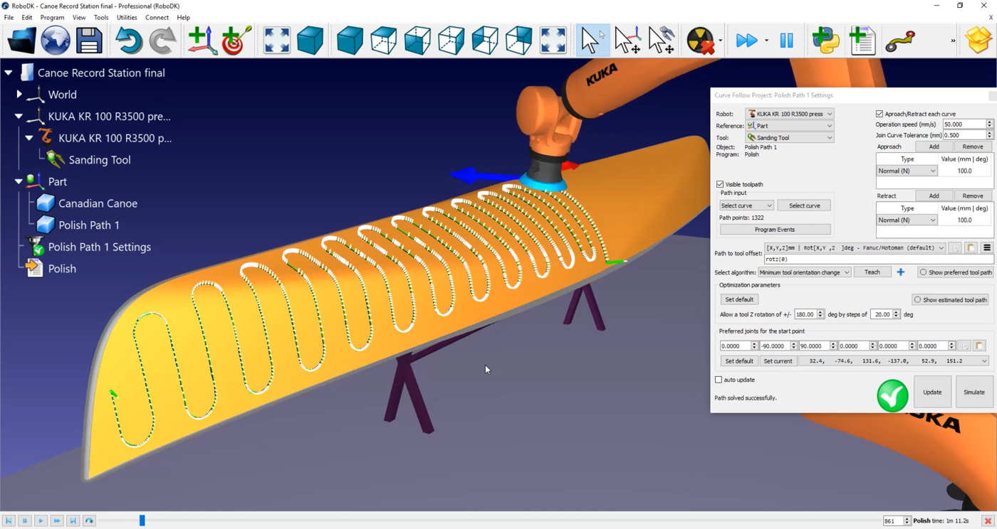
You can modify the approach and retract speed by selecting
In this menu you can also activate the Set Rounding option. By default, every white line along of your path is a point that will be sent to your robot controller as points were the robot needs to stop. In a polishing or sanding application, this it is not the best behavior.
Activate the Set Rounding checkbox to activate the continuous movement option in your controller. Depending on the robot brand the name of that option can be “rounding”, “constant movement” or “zone data”. In this example the value will be 0,5mm.
In this example, since we are using a KUKA robot you’ll obtain an SRC file when you generate the robot program. This file that can be read by a KUKA KRC controller.
Follow these steps to generate a robot program:
1.Right click on 
2.Select OK.
3.Right click on