Create a Mechanism or a Robot
You can model new mechanisms with RoboDK, this includes turntables, one to three linear axis mechanisms, different types of robot arms, Scara robots, AGVs, CNCs and grippers.
Following these steps to create a new robot or mechanism:
1.Select Utilities➔Model Mechanism or robot.
2.Select the type of mechanism or robot you want to create.
3.Select the coordinate system that represents the origin of your mechanism.
4.Select one object for each joint (moving part of the mechanism or robot).
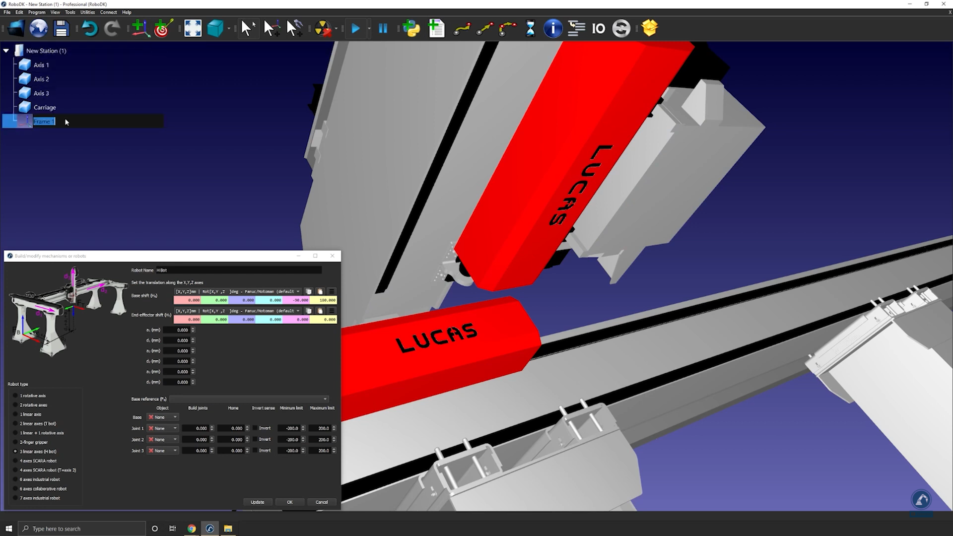
5.Enter the robot parameters as described in the corresponding image.
6.Select Update to see the new mechanism.
You can also modify existing mechanisms by right clicking the robot item in the tree and selecting Modify robot. This option is available for robots and mechanisms that you created yourself.
You can create the following types of mechanisms and robots in RoboDK:
●One rotative axis (a turntable or a gripper)
●Two rotative axes (for example: a 2-axis positioner)
●One linear axis (such as a linear rail)
●Two linear axes (such as a T-bot)
●Three linear axes (such as an H-bot)
●One linear axis + one rotative axis
●Two-finger grippers
●Scara robots (4-axis)
●Six-axis robot arms
●Seven-axis robot arms
How to model a one-axis turntable
This section shows how you can model a one-axis turntable. Turntables are often used for robot machining applications.
Follow these steps to create a turntable:
1.Load the 3D models of the turntable: drag and drop 3D models to the RoboDK window (such as STL, STEP or IGES files).
2.Select Utilities➔Model Mechanism or Robot.
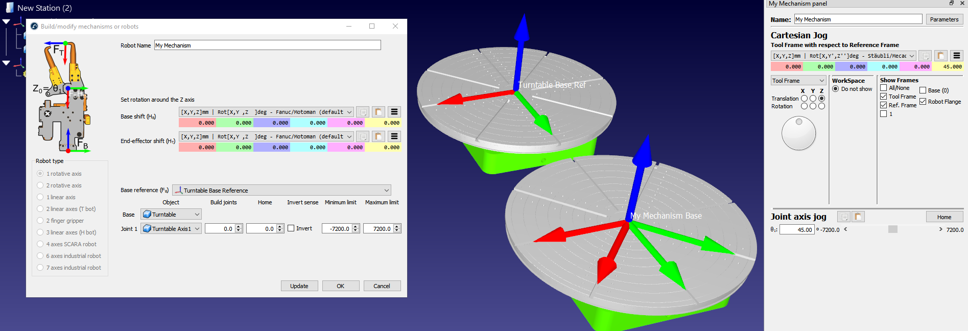
3.Select 1 rotative axis.
4.If you look at the image, it should show you how the base and top plate should be positioned. In the case of a rotative axis, the mechanism will rotate around the Z axis of Fb (Frame Base)
5.Rename your mechanism to TurnTable.
Define the reference of your turntable by creating a new coordinate system:
1.Create a reference frame and select F2 to name it to Frame Base.
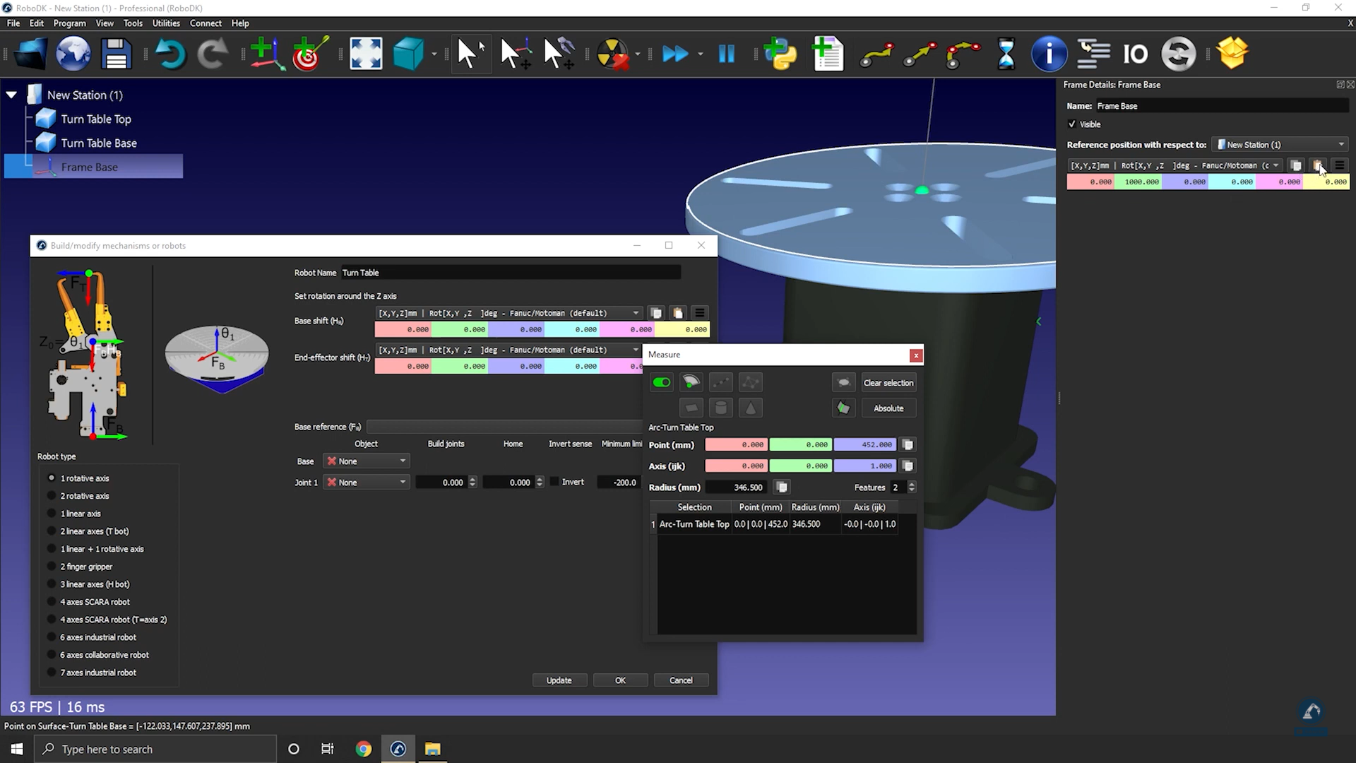
2.Modify the position of the frame by opening Frame Panel.
3.Select Tools and then Measurement.
4.Measure the position of the surface by clicking on the mechanism; You can see the difference between the origin and the center. You can copy the values and paste them as shown in the image below.
The reference position should now match the reference in the image. The reference frame and the object items should be automatically populated. If the automatic selection is not correct you can update it accordingly.
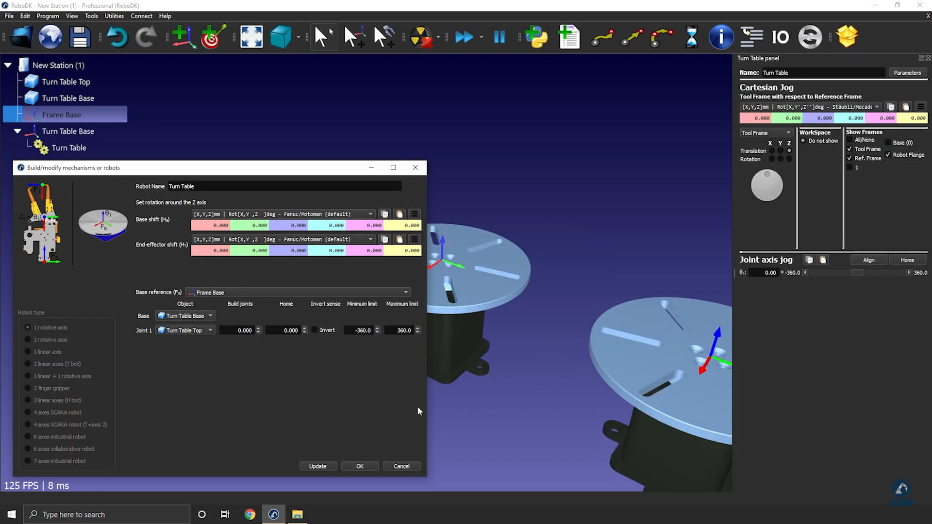
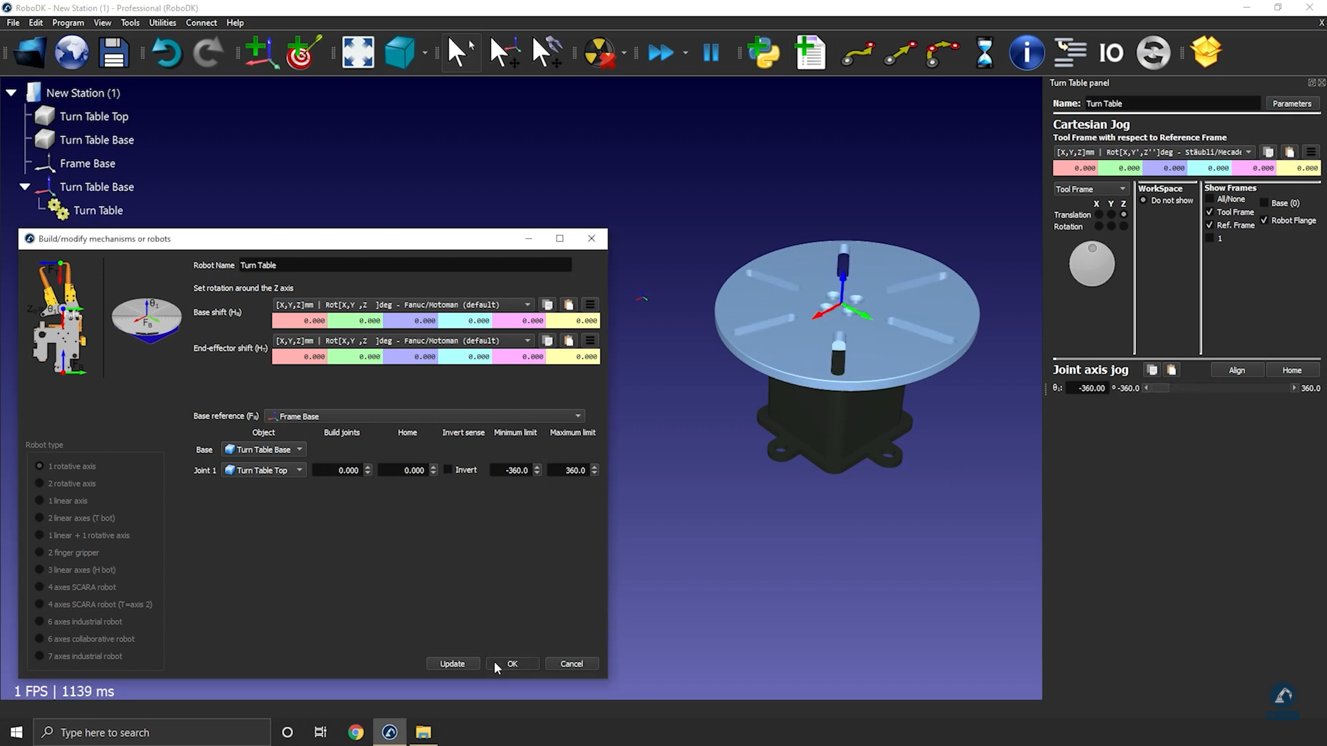
6.You can update the joint limits, for example, if we want to have +/-20 turns we can enter +/-7200 deg. You can also change the joint limits later by double clicking the joint limit labels of the robot panel.
7.Select Update to generate the mechanism: the new mechanism will appear.
8.You can select OK to close the menu or add additional changes to your turntable if required.
9.You can delete the original object files you used to create the mechanism. The mechanism will be saved with your RDK project, and it does not require any external dependencies.
10.Once you have tested your table (make sure that it is moving in the right direction and that the limits are what you were expecting), you can select OK on the Model mechanism window to close it.
How to model a one-axis linear rail
This section shows how to model a 1-axis linear rail, also known as a linear axis or linear track. A linear rail helps extending the reach of robot arms.
Follow these steps to import your 3D model:
1.Drag and drop your 3D model in RoboDK to import the objects into your station (accepted file formats include STEP, IGES or STL are common 3D formats).
Follow these steps to open your mechanism builder:
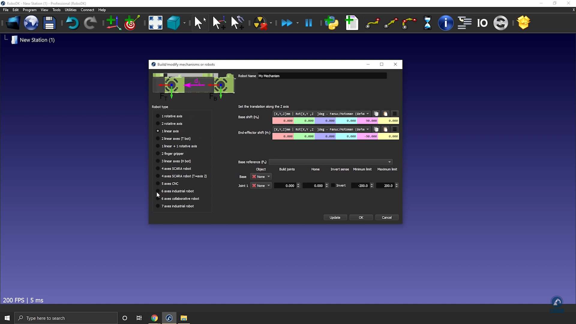
2.Select Utilities ➔Model Mechanism or Robot.
3.Make sure 1 linear axis is selected under “Robot Type”.
4.If your 3D model is grouped in one piece, you can split your model inside of RoboDK.
Follow these steps to position your base frame:
5.Now that you have the objects loaded, open your model mechanism builder again Utilities ➔Model Mechanism or Robot.
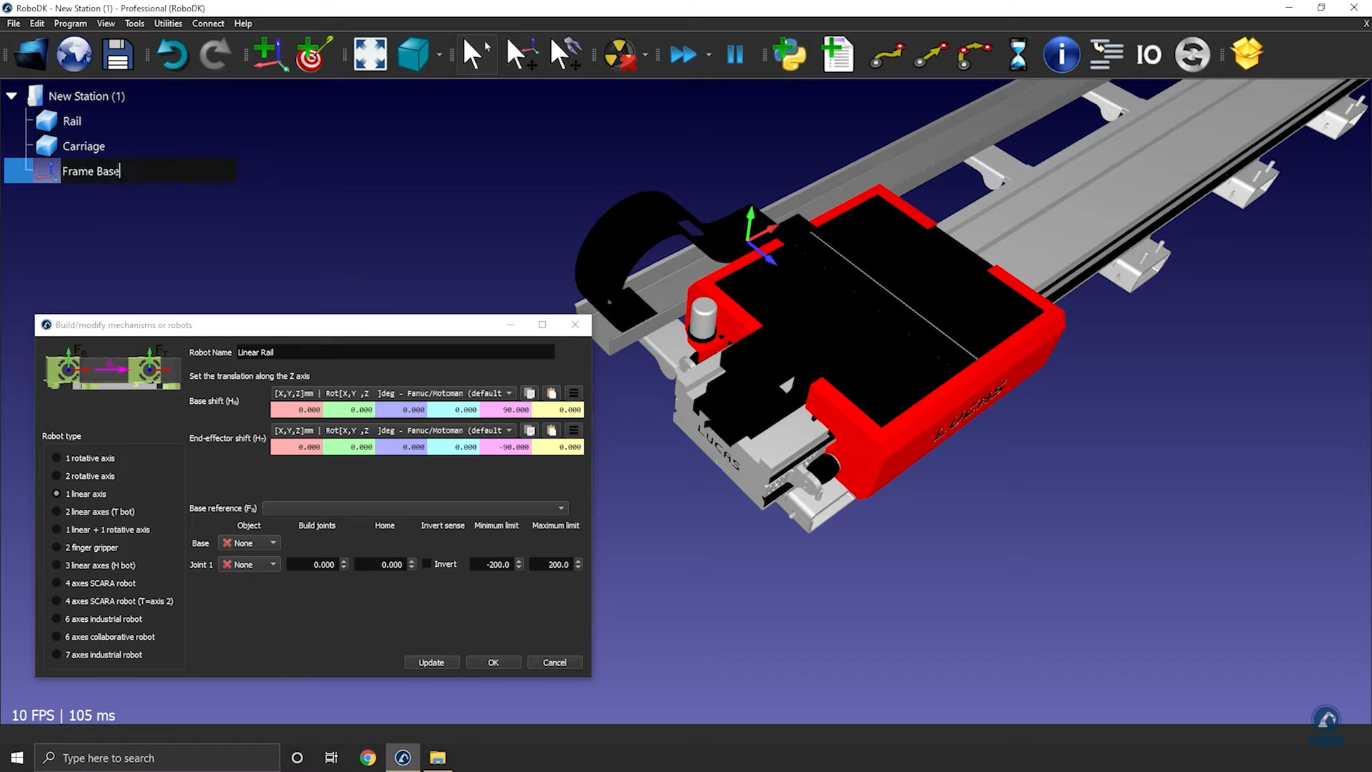
6.You can rename your mechanism under Robot Name.
7.Consider that your base frame should be at the 0 position of the rail: Create a reference frame there and name it Frame Base.
Follow these steps to modify the position of the frame:
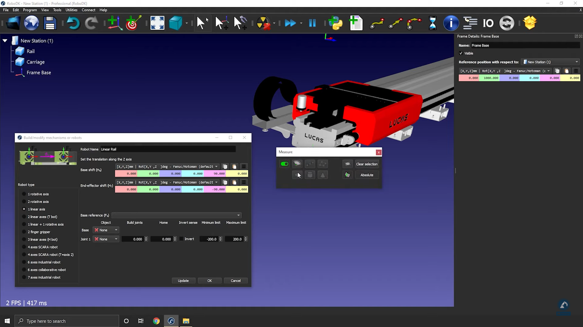
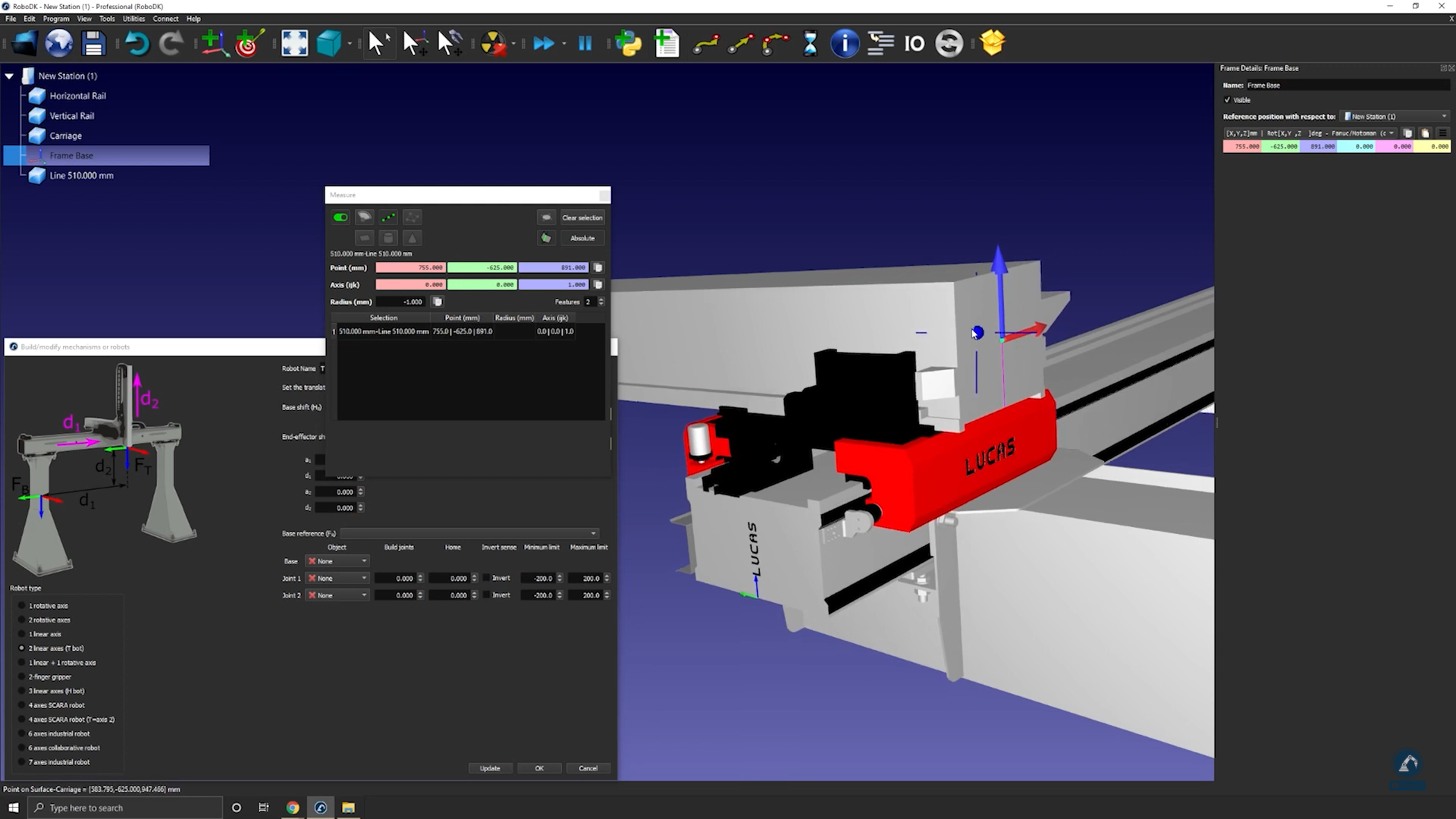
8.Select Tools ➔ Measure.
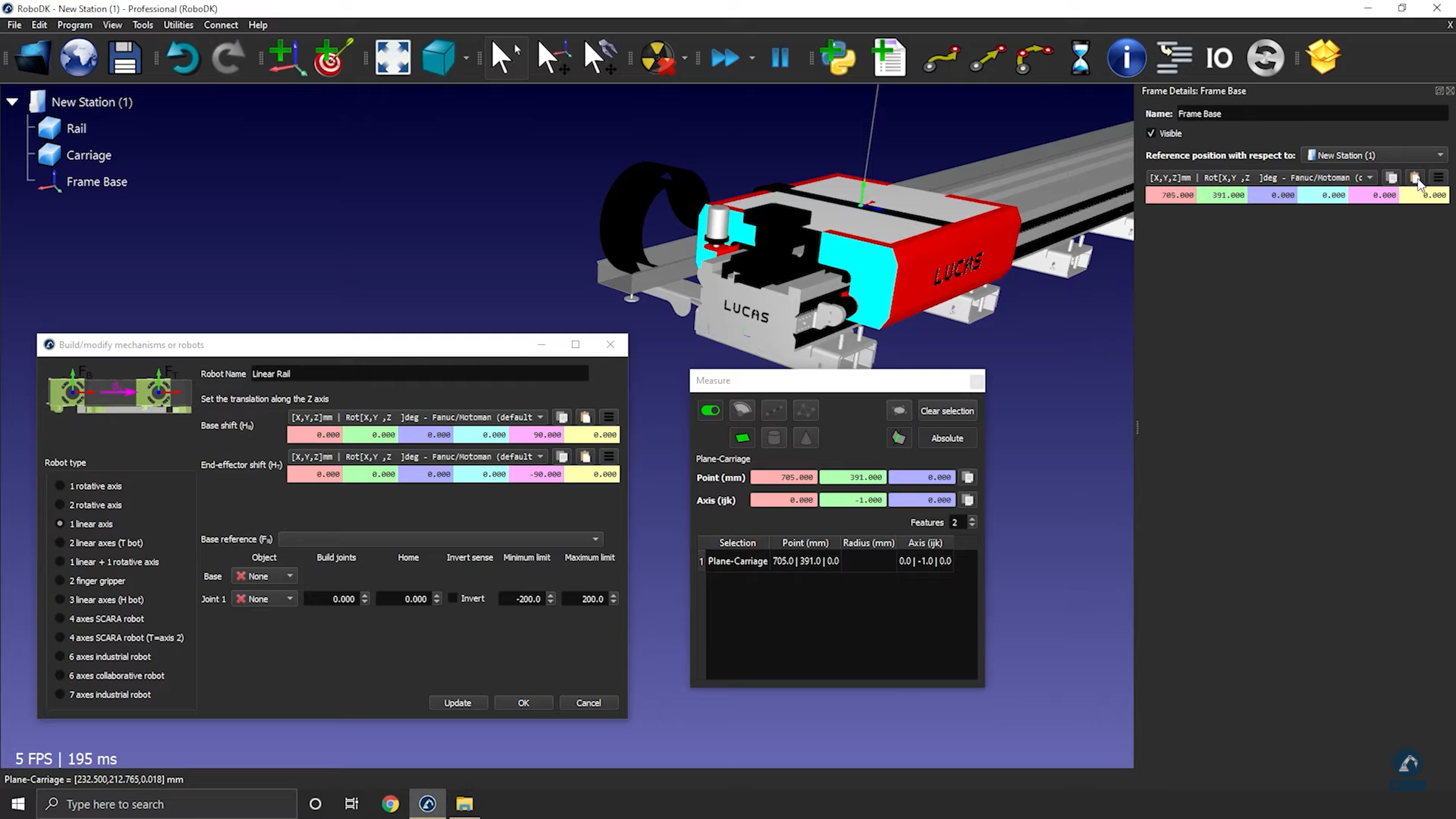
9.Use the measure tool to measure the position of the surface by selecting the icon (as shown in the image below).
10.Copy the values and paste under Frame Details: Frame Base (as shown in the image below).
Follow these steps to check orientations and to enter the rail length:
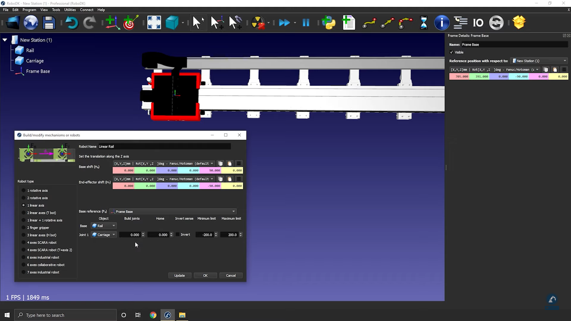
11.Rotate clockwise, 90 degrees around X: Enter the value -90.000 degrees in the reference position window.
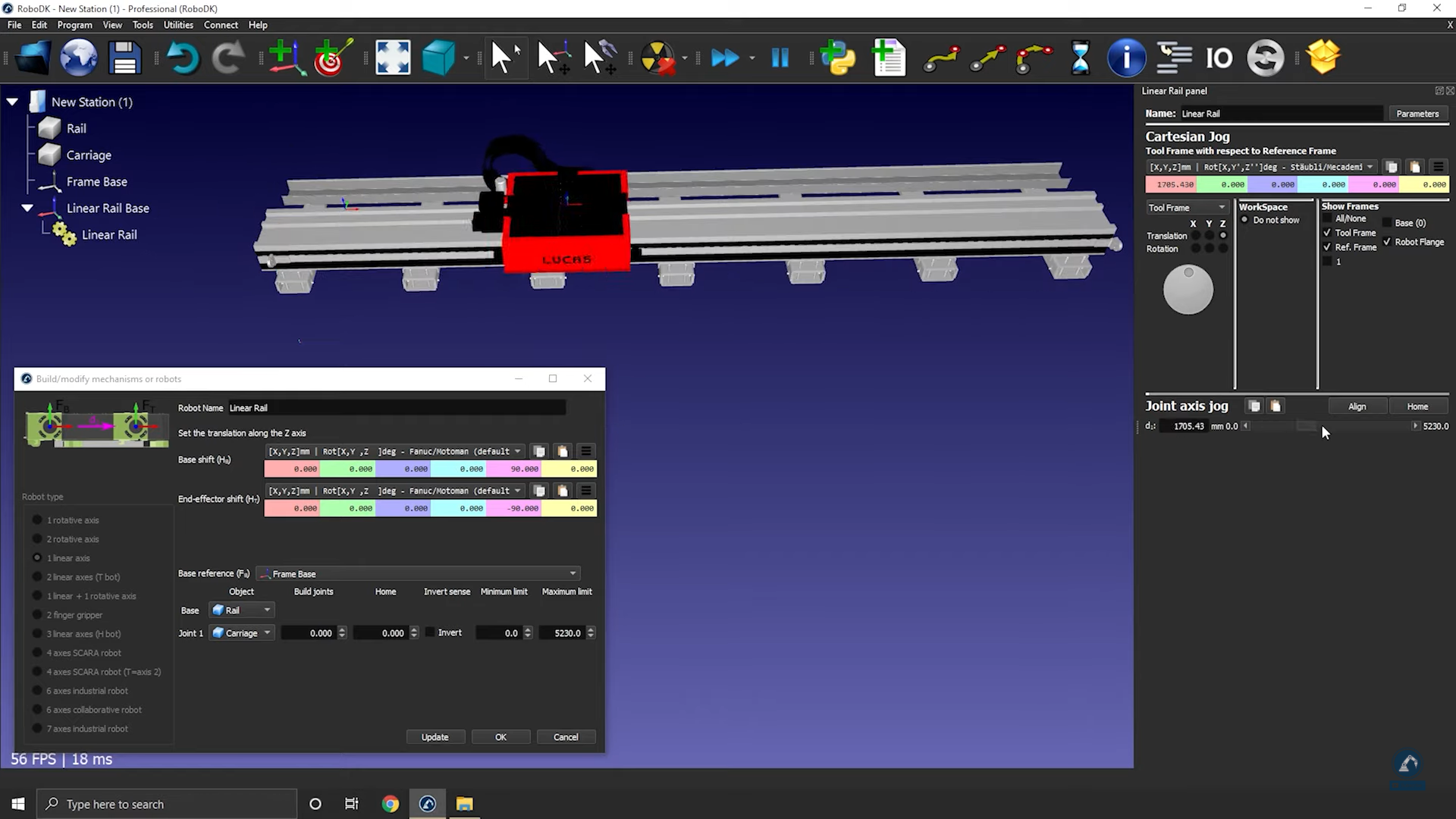
12. Enter the length of the rail in the model mechanism window (as shown in the image below).
13.Select Update to create the robot.
14.You can test the rail (make sure that the limits are good and that it is moving in the correct direction) by using the joint axis jog.
15.Select OK when you are satisfied with the results.
How to model a two-axis linear rail
This example shows how to model a 2-axis linear rail, also known as a linear axes or linear track. Linear axes are used to extend the reach of robot arms.
Follow these steps to set up your 3D model in RoboDK:
1.Import your 3D model into RoboDK ➔ drag and drop the STEP file into your station.
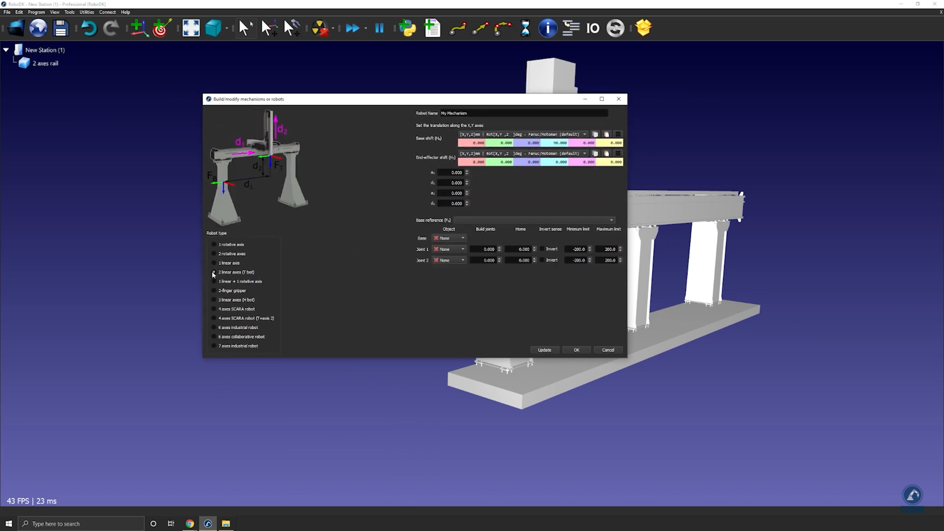
2.Open the Mechanism builder: Utilities ➔ Model Mechanism or Robot.
3.Under Robot Type, select 2-linear axes (T-bot).
4.Once your model is split into 3 pieces, re-open the rail builder: Select Utilities ➔ Model Mechanism or Robot.
5.Select the option: 2-linear axes (T-bot).
6.Rename your robot to T-bot (under robot name).
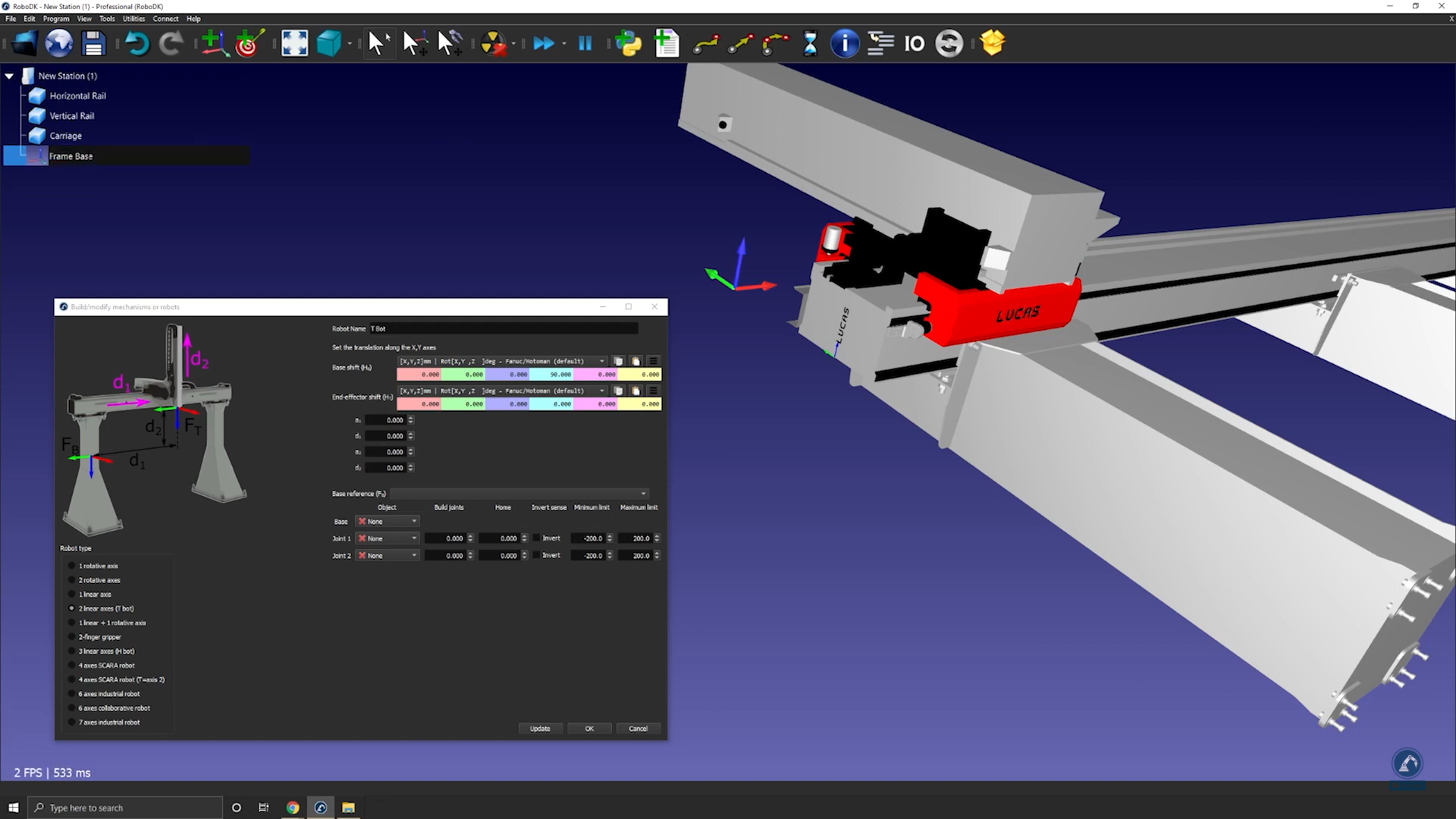
Follow these steps to find the location of your base frame:
7.If you consider that your base frame should be at the 0 position of the rail, create your reference frame exactly there and rename it to Frame Base.
Follow these steps to modify the position of the frame:
8.Open the frame panel by double clicking the frame.
9.Measure the position of the center of the surface by opening your measurement tool: Tools ➔Measure.
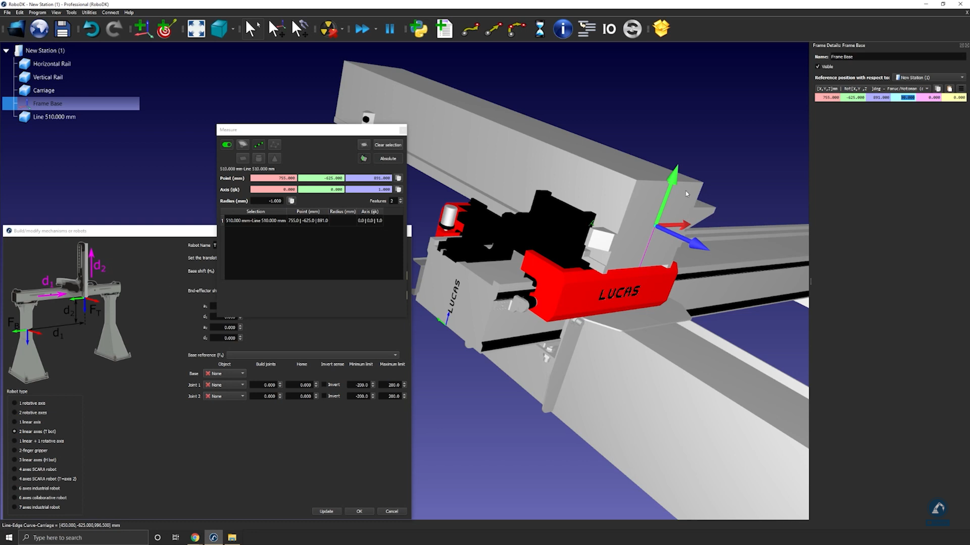
10.Select the center point of each edge (as shown below) to find the distance between the two lines.
11.Select Create Geometry in the Measure window which will create a line between the two points.
12.Select Clear Selection.
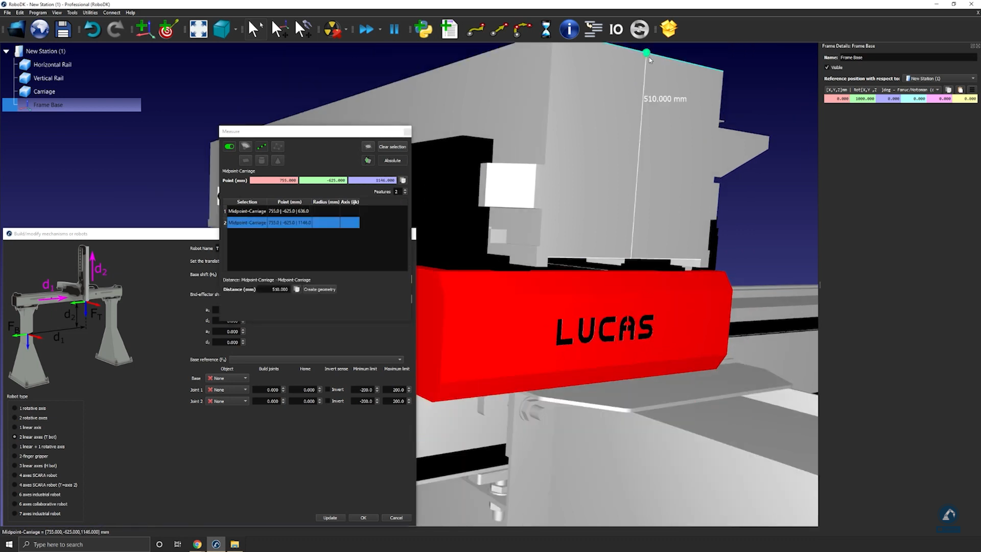
Follow these steps to measure the position of the center point between the two lines:
13. Select the center point of the line.
14.Copy the values in the Measurement window and paste the values as the frame position (as shown below).
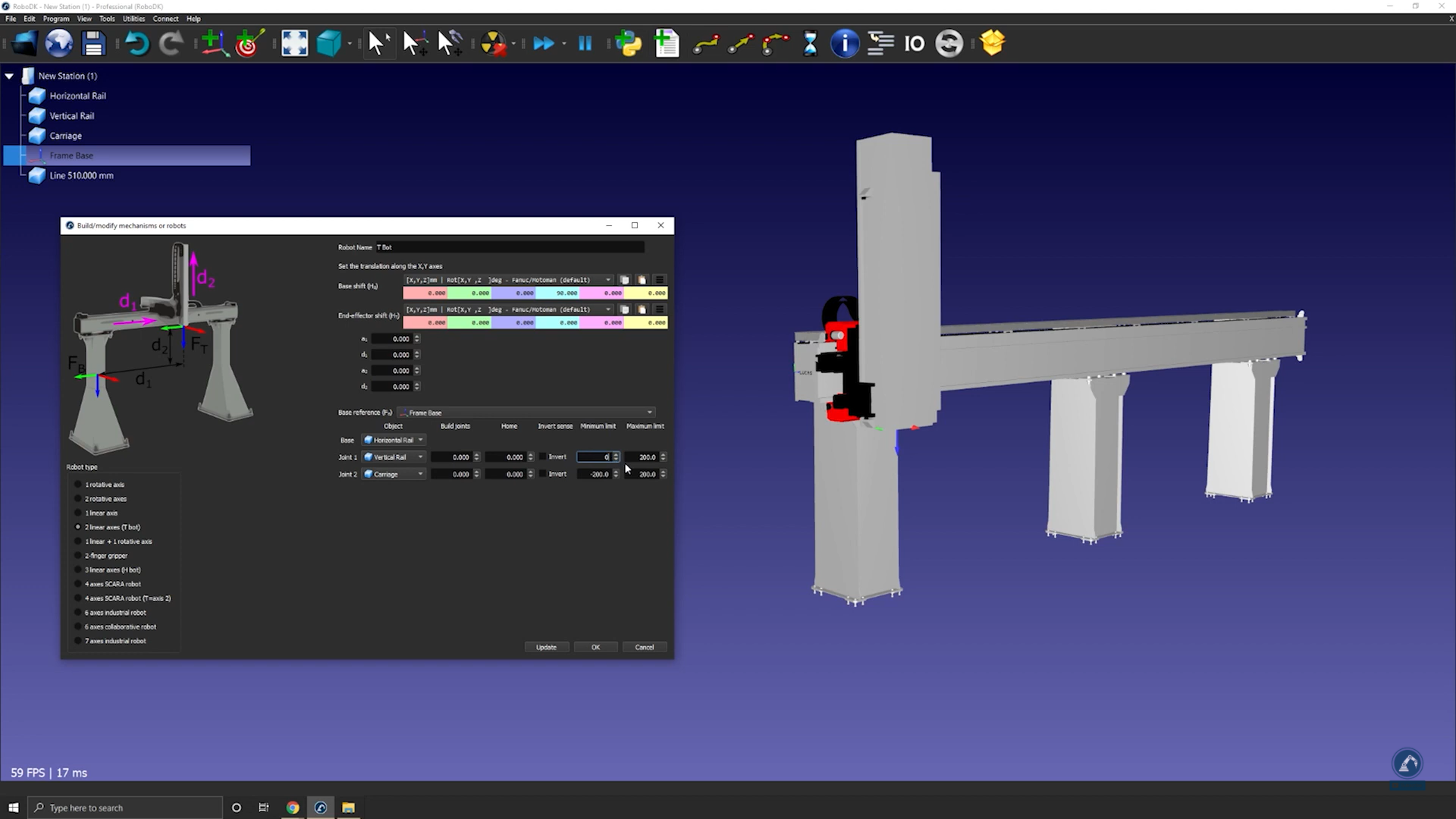
Follow these steps to make sure the orientations are the same:
15.Rotate counterclockwise, 90 degrees, around X and then rotate 90 degrees around the Z axis (as shown below).
16.Enter the measurements of the rail in the Model Mechanism or Robot window as show below.
17.Select Update to create the robot.
18.If you are satisfied with the results, select Ok in the “Model Mechanism or Robot” window.
How to model a three-axis Cartesian robot
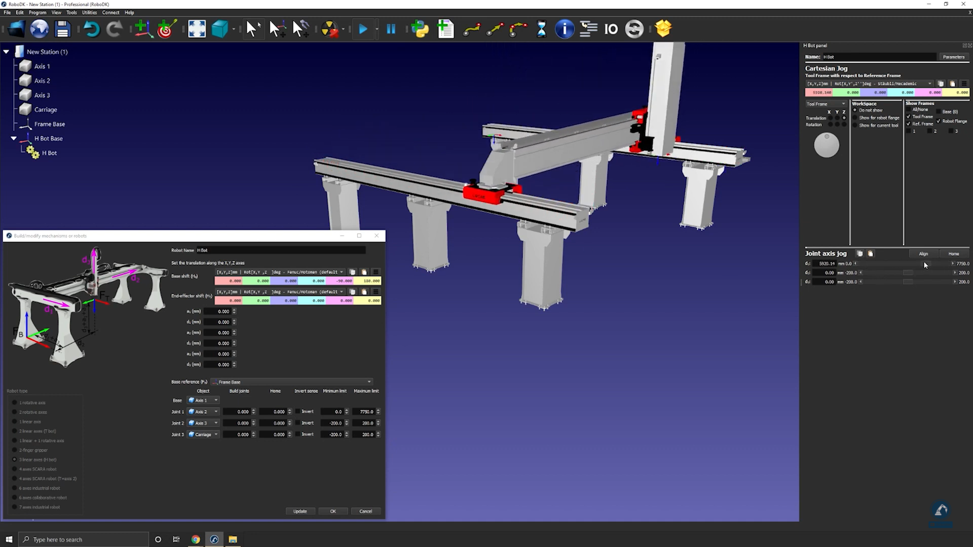
The following video shows how to model a 3-axis Cartesian robot (H-bot). Robot arms can be mounted on external axes to extend their reach.
Follow these steps to set up your 3D model in RoboDK:
1.Drag and drop the 3D model (such as a STEP or IGES file) in RoboDK to load it into your station.
2.Open the mechanism builder: select Utilities ➔Model Mechanism or Robot.
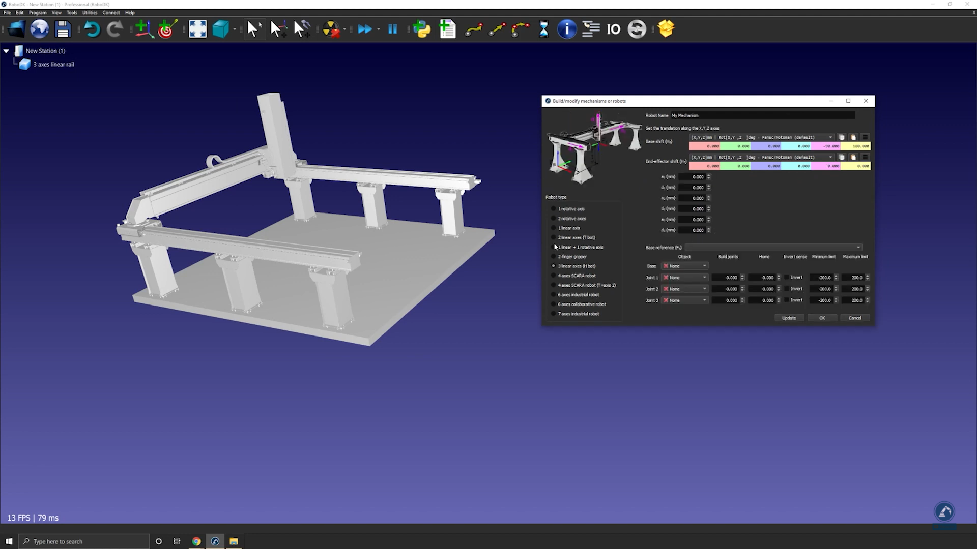
3.Under Robot Type, select 3-linear axis (H-bot).
Follow these steps to create your Base Frame:
4.Once your object is split into different pieces, re-open the rail builder (select Utilities➔Model Mechanism or Robot➔3-linear axis).
5.Rename your robot under Robot Name.
6.Create a reference frame at the 0 position of the rail. You can rename it as Frame Base.
Follow these steps to modify the position of the frame:
7.Open the frame panel by double clicking “Frame Base”.
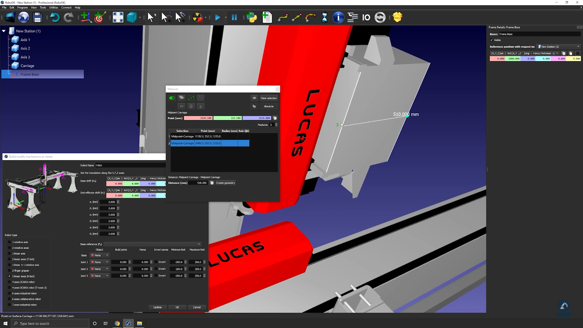
8.Open the measurement tool: Tools➔Measurement.
9.Select the icon that is highlighted below in the measurement tool and then select both edges of your object to find the distance between both center points.
10.Select Create Geometry to create a line between both center points.
11.Now that the line between both points is created, you can select Clear Selection.
12.Select the center of the line to find the measurement of the center point of your newly created line.
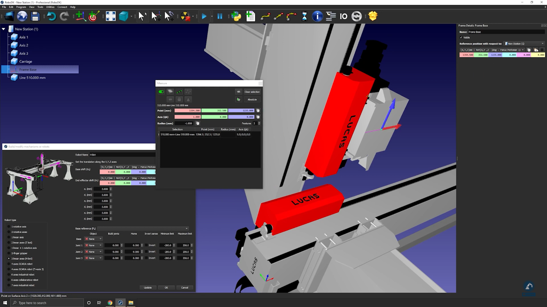
13.Copy the values and paste them as the frame position (as shown in the image below) to make sure that the frame position matches with the reference image.
Follow these steps to make sure that the orientations are the same:
14.Rotate 90 degrees counterclockwise.
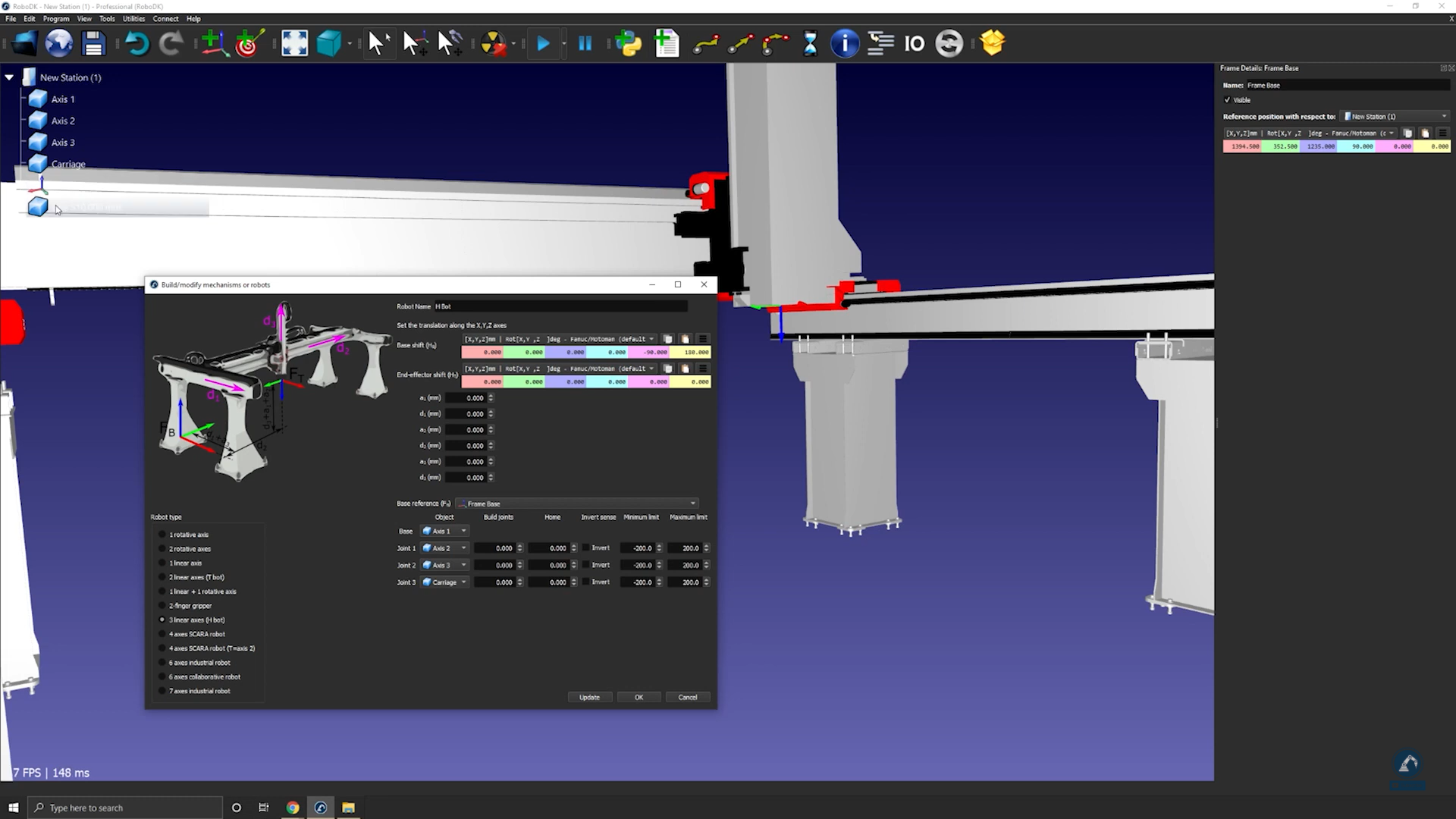
15.Select Frame Base and then select the rail 3D models (select each section one by one) as shown in the image below.
16.Enter the length of each rail in the measurement section.
17.Move each axis under Joint Axis Jog to make sure each axis is moving fine.
18.Press Update after testing each axis to create your robot.
19.If you are fine with the results, you can press Ok on the model mechanism window.
How to model a two-finger parallel gripper
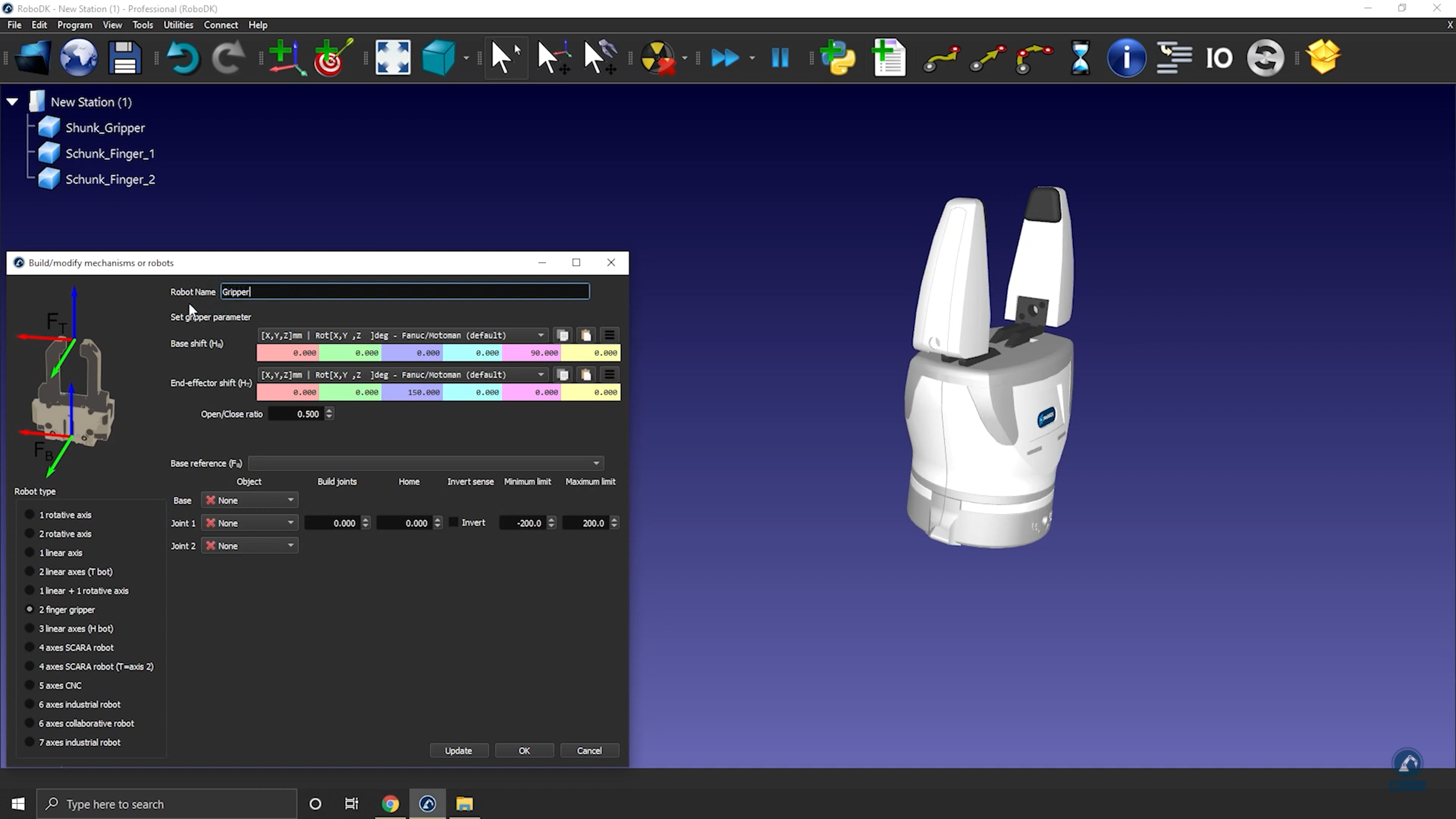
You can model a parallel gripper in RoboDK by using the Model Mechanism or Robot tool. Parallel grippers are also called 2-finger grippers and allow a robot to grab parts.
Follow these steps to set up your 3D model in RoboDK:
1.Import your 3D model: Drag and drop your STEP file to load it into your station (IGES or STL files will also work).
2.Open the mechanism builder: Utilities ➔Model Mechanism or Robot.
3.Select 2 Finger Gripper under “Robot Type”.
4.You can rename your robot “Gripper”.
Follow these steps to position your base frame:
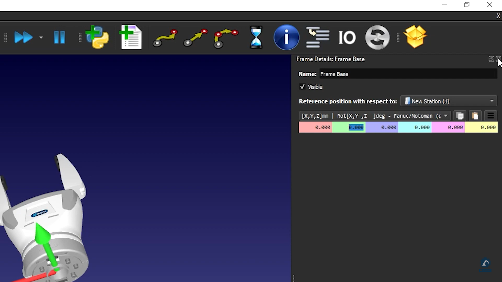
5.Create a reference frame (it should be below the gripper), and rename it as Frame Base.
6.Make sure that the frame you just created is positioned according to the image: Bring the reference frame to 0.000 mm (X,Y,Z).
7.Enter the gripper range of motion: If you put the fingers at the 0 position, the minimum limit will be 0 and the maximum limit will be 80.
8.Select Update.
9.Make sure it moves in the right direction and that the limits are good by using the Joint Axis Jog.
10.If you are fine with the results, you can press Ok.
How to model a six-axis robot arm
This example shows how to model a 6-axis industrial robot arm from scratch, using the 3D models provided by the manufacturer.
Follow these steps to gather some information about your robot:
1.Firstly, you need the 3D models (such as STEP or IGES files).
2.You will also need the robot data sheet or robot manual.
Follow these steps in RoboDK to open the robot model window:
3.Select Utilities➔Model Mechanism or Robot.
4.Under Robot Type, select 6 axis industrial robot.
Load your robot 3D files onto RoboDK by doing the following:
5.Drag and drop your robot into RoboDK or select file and then open (it may take a few seconds to load).
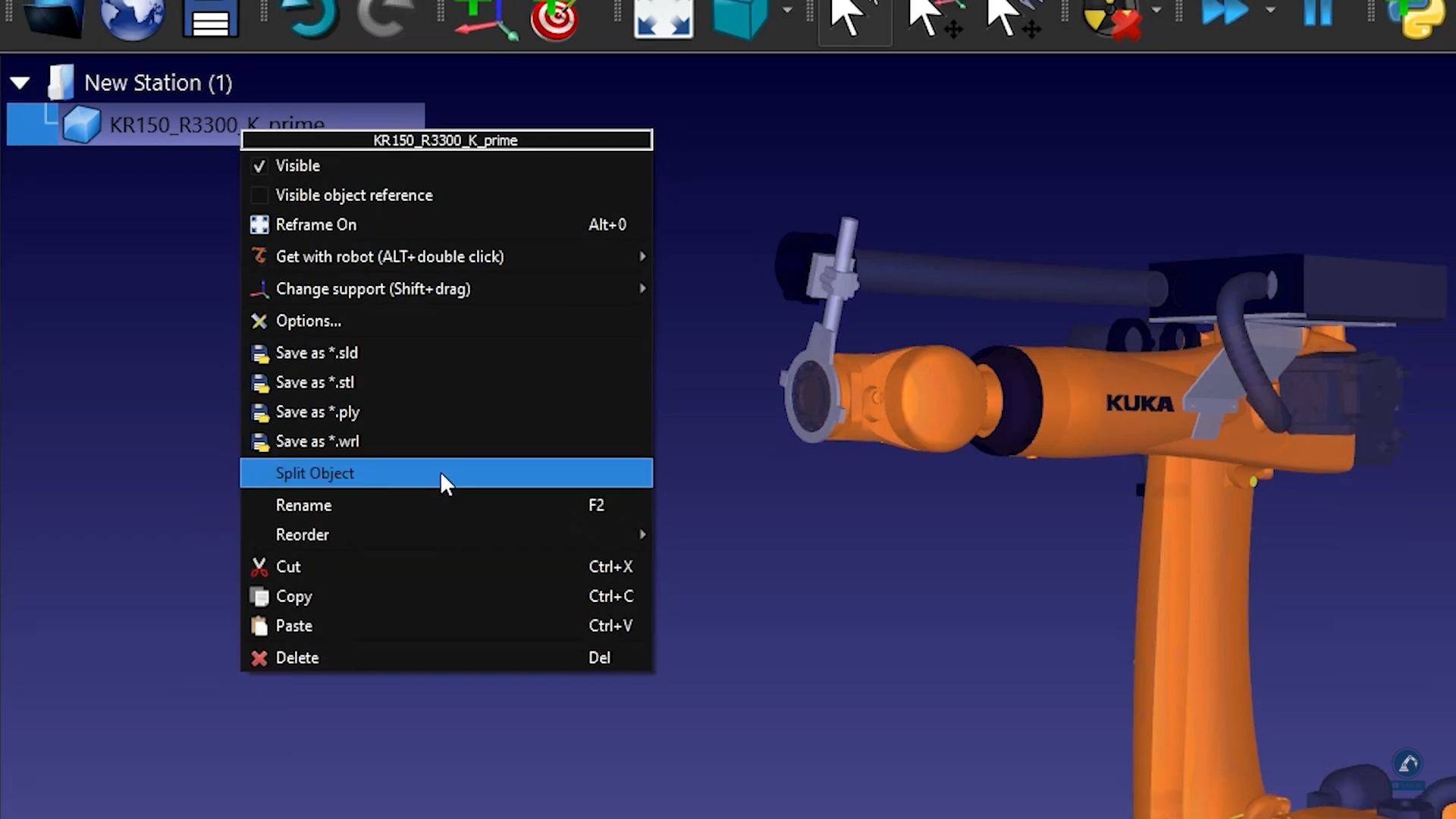
Follow these steps to split an object into different pieces so that we can treat each piece separately:
6.If the CAD file that you downloaded is in one single object, you can ungroup the object (STEP file) by right-clicking on any object and selecting Split Object.
7.You can then regroup it to create the different pieces of the robot.
Follow these steps to enter the robot kinematics information in RoboDK:
8.Give your robot a name by entering it in Robot Name.
9.If the pieces of your robot are in the right order, then all of the 3D models should be populated correctly. Otherwise, you can manually link each object to the right robot joint.
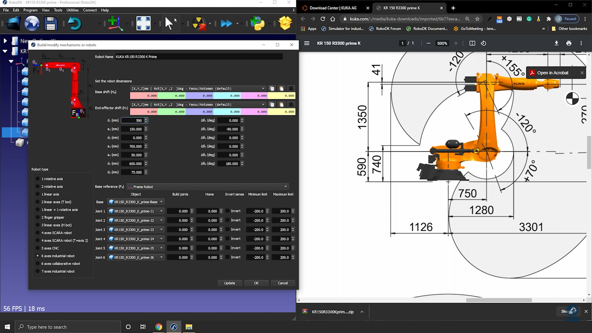
10.Fill in the dimensions of the robot by opening the data sheet.
11.On the 3D sketch of the data sheet, you will find all the values that you are looking for. Fill in the correct values in RoboDK.
12.Once you are satisfied with the result of the robot kinematics, select Update.
How to couple robot joints together
Some robots have two joints coupled together, which means that two of the joints of the robot are dependent. For instance, Fanuc robots have joint 2 and joint 3 linked together.
Follow these steps to couple the joints of your robot in RoboDK:
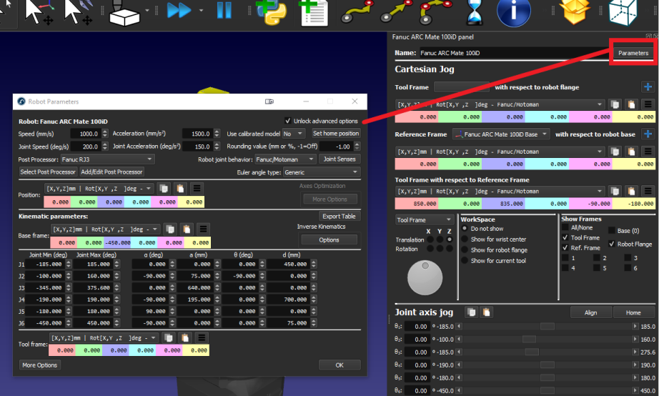
1.First, double click on the robot to open robot panel.
2.Click on Parameters to open the Robot Parameters tab.
3.Check the Unlock advanced options box.
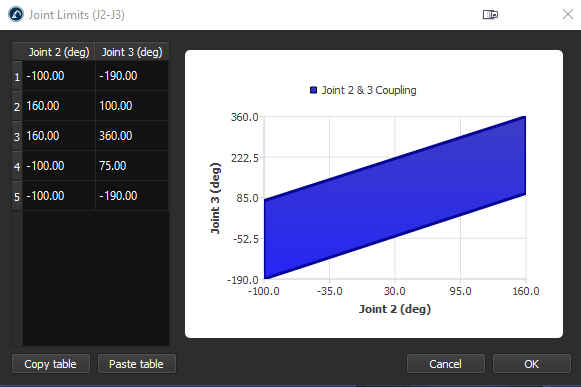
4.Click on Joint Senses to open the Joint axis sense tab. The first 6 values represent the joints turning direction and the last value is the coupling of joint 2 and 3. Change the 7th value to -1 to link the joints. A new tab with the coupling joint limit polygon will open, you can edit the limits to prevent the robot from colliding with itself.
