General Tips
This section covers general tips for defining your tools, coordinate systems and importing 3D models in RoboDK to build your project in RoboDK.
This section covers the following topics:
●How to Calibrate a Tool (TCP)
●How to Calibrate a Reference Frame
●Tips Importing STEP or IGES files
●How to change the Simulation Speed
●How to calculate the Cycle Time of a program
Define a Tool (TCP)
The robot tool, or Tool Center Point (TCP), is the point used to move the robot to a Cartesian position (such as a Cartesian target given XYZWPR values). The TCP is defined as a transformation from the robot flange. Defining the TCP properly is important in any robot application, either if it involves Offline Programming or not.
Follow these steps to define or calibrate a robot tool (Tool Center Point, or TCP):
1.Select Utilities➔
2.Select the Tool to define/calibrate.
Alternatively, right click a tool and select 
3.Select the method:
a.Touching a point with the tip of the TCP, using different tool orientations (Calib XYZ by point)
b.Touching a plane with the TCP, using different tool orientations (Calib XYZ by plane). The TCP can be a point or a sphere.
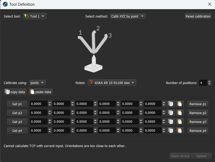
4.TCP calibration using joint values is the default setting. Change it to poses if you have the Cartesian targets.
5.Select the robot if more than one robot is available in your project.
6.Adjust the number of points that you would like to use to calibrate the TCP. This value can also be modified later.
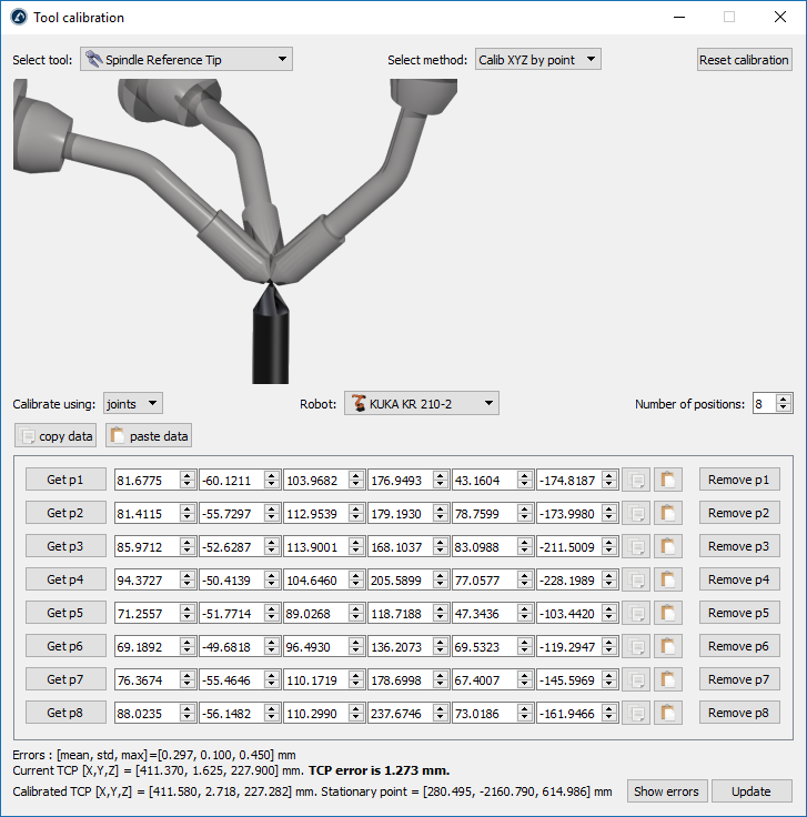
7.Start filling the table with the measured configurations (joint values or position and orientation of the flange).
8.Finally, select Update to apply the new position tool selected in the RoboDK Station.
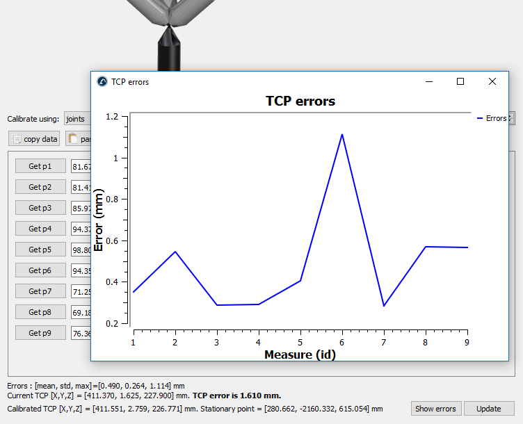
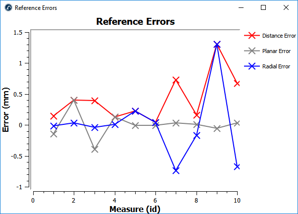
As an example, the following image shows the errors before point 6 was deleted by selecting the Remove p6 button.
Define a Reference Frame
A Reference Frame defines the position of an object with respect to a robot (position and orientation). It is recommended to teach targets with respect to a reference that you can define with your robot. A reference frame allows you to adjust or move your programs to different locations without having to re-teach all your targets.
More information about reference frames is available in the Getting Started Section.
Defining a reference frame requires probing some points using a robot tool (the joint values need to be retrieved at specific locations).
Follow these steps to identify a reference frame with respect to the robot:
1.Select Utilities➔
2.Select the Reference Frame to define/calibrate.
Alternatively, right click a Reference Frame and select
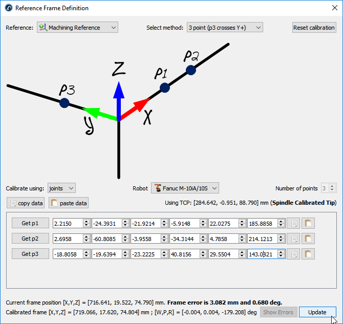
3.Select the method:
a.3-point method (with the 3rd point crossing the Y+ axis)
b.3-point method (with the 1st point being the origin of the reference frame)
c.6-point
d.The Turntable Calibration option allows locating the reference frame on a turntable, having the turntable axis properly aligned
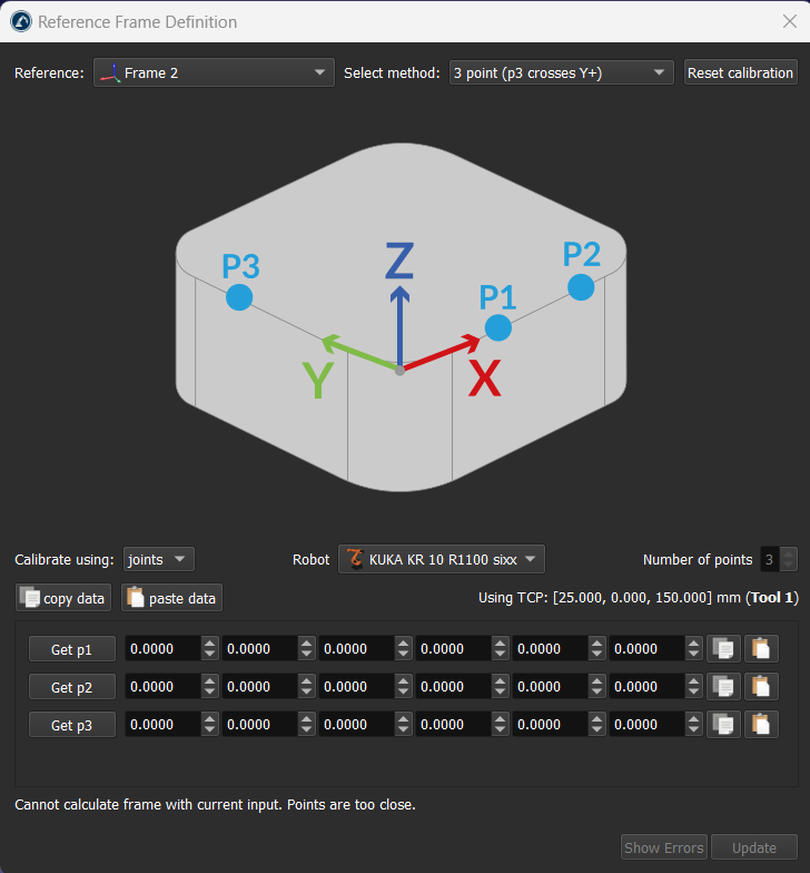
4.Joint values are used as the default setting. Change it to points if you have the XYZ position of each point with respect to the robot base frame.
5.Select the robot if more than one robot is available.
6.Start filling the table with the measured points (joint values or points).
7.Finally, select Update to apply the new position to the reference frame selected in the RoboDK Station.
Align object with reference
This section explains how the reference frame (coordinate system) of an object can be aligned with respect to its own geometry. This section allows moving the reference frame of an object to a location that can be identified in a real setup.
Follow these steps to virtually align the reference frame of an object according to specific points of the object geometry:
1.Load the object
2.Select the active 
3.Select Program➔
Make sure the reference frame is directly attached to the station root (not to other Reference Frames).
4.Right click the reference frame and select
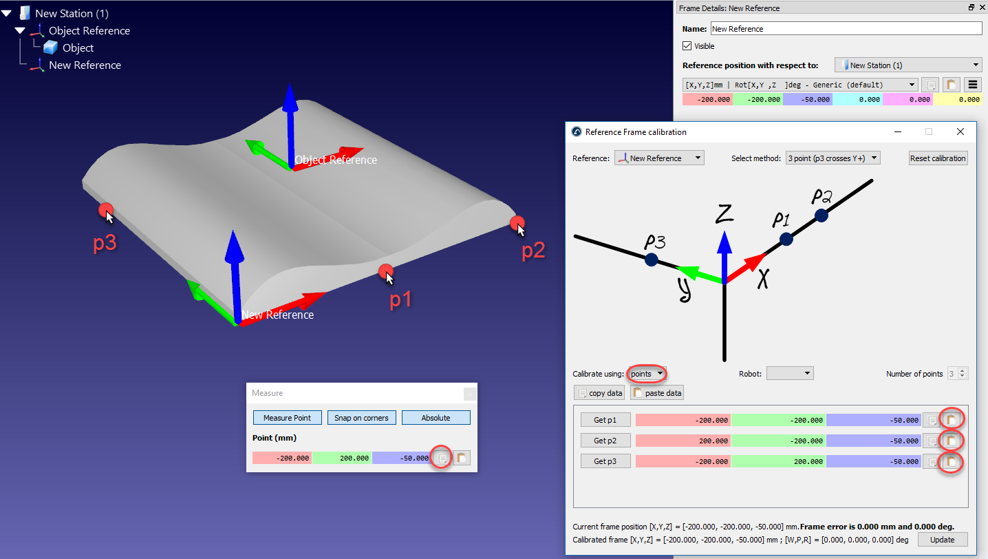
The procedure is very similar to the previous section. The main difference is that we must select the points of the virtual object instead of the real object.
5.Select the desired calibration method.
For example: The 3-point method (with the 3rd point crossing the Y+ axis).
6.Select Calibrate using points
7.Select Tools➔Measure to open the Measurement Tool
8.Select the Absolute button in the Measurement Tool so that the points are measured with respect to the Station (absolute reference)
9.Select the 3 points on the virtual object (one by one) and enter them in the Reference Frame calibration window
10.Select Update. The reference frame should appear at the desired location.
11.Right click the object and select Change support. Then, select the new reference frame. The absolute position of the object will not change. However, the relative position of the object with respect to the new reference frame will be properly defined.
12.The object and its own reference are ready for Offline Programming: Drag and drop the new reference frame to the robot reference frame.
Align robot references
This section explains how two or more robots can be programmed offline while sharing a common reference frame.
In a typical offline programming application, the position of the object is updated with respect to the robot. However, when two or more robots are used for the same application, the position of each robot must be updated with respect to one common reference (a reference object or a common reference frame).
Follow these steps to update the position of two or more robots with respect to a reference frame:
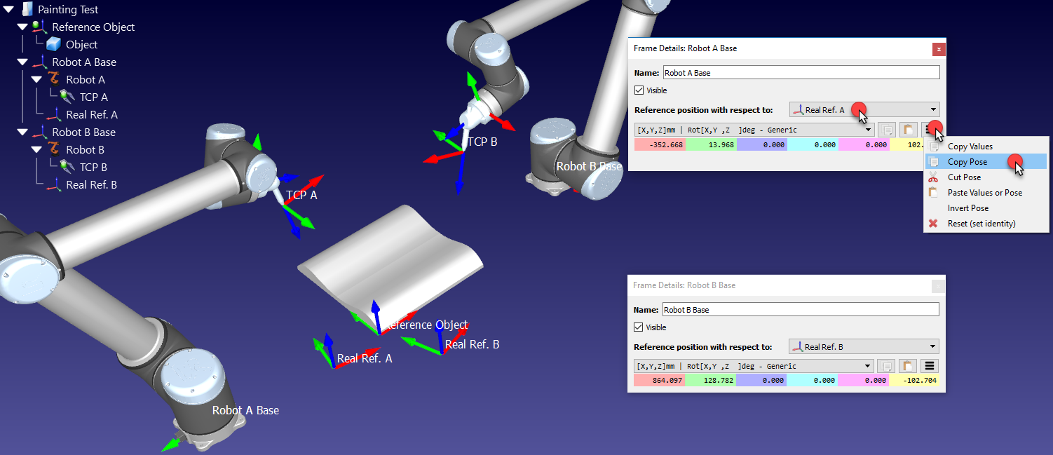
1.Make sure the robot reference frames and the object reference frame do not depend on each other. If there is a dependency we should place the reference frames attached to the station item.
2.Add a new reference frame attached to each of the robot base frames as if you were going to define a new individual reference frame for each robot (Real Ref. A and Real Ref. B).
This reference frame will represent the real location of the part with respect to each robot.
3.Calibrate each of these reference frames (Real Ref. A and Real Ref. B), separately, using the standard Reference Calibration procedure (3-point method for example)
At this point we will see 3 reference frames that should be coincident, but they are not. The reference frame of each robot must be updated to fix this issue:
4.Double click one of the robot references, such as Robot A Base to open the reference frame window
5.Copy the position of the robot base reference with respect to the calibrated reference of that robot (Real Ref. A), by selecting the copy button
6.In the same window, change the Reference position with respect to (dropdown) to the Reference Object
7.Paste the copied position. The robot will be moved and the Real Ref. A will be coincident with the Reference Object frame
8.Repeat steps 4-7 of this procedure for the other robots, if any
At the end of this procedure all reference frames should match and the relationship between all the calibrated references and the Reference Object should be the same.
Calibrate a Turntable
The Reference Frame definition utility described in the previous section provides two ways of calibrating the position of a turntable with respect to a robot. The calibration/identification of the turntable can be done using the robot with a properly defined tool or a measurement system (such as a laser tracker).
We need to retrieve the position of one point in the turntable multiple times as we move the turntable axes. We currently support calibrating 1-axis and 2-axis turntables.
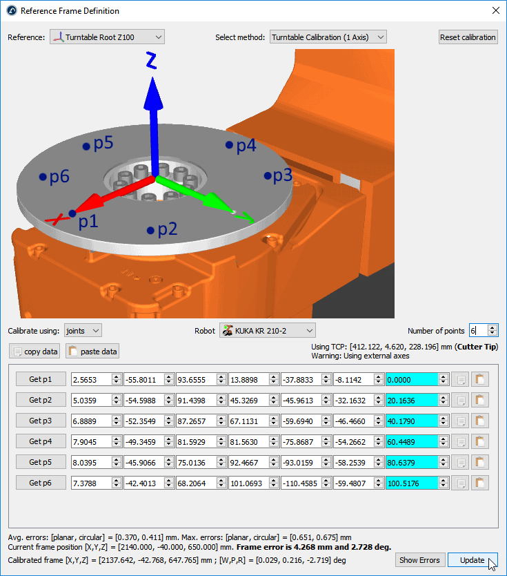
Calibrate a one-axis Turntable
This section guides you to calibrate a 1-axis turntable. You can calibrate your 1-axis turntable using a well-defined TCP and a static point on the turntable.
Follow this procedure to calibrate your 1-axis turntable.
1.Select Utilities➔
2.Select the Reference Frame to define/calibrate. Alternatively, right-click a Reference Frame and select
3.Select the method Turntable Calibration (1 Axis)
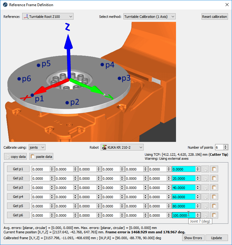
4.Select Calibrate using joints (default setting). You can change it to points if you have the XYZ position of each point with respect to the robot base frame.
5.Specify the robot if more than one robot is available in the station.
6.Select the number of points you would like to take (the minimum required is 3).
7.Start filling the table with the robot joint positions (or points).
8.Finally, select Update to apply the new position to the reference frame selected in the RoboDK Station.
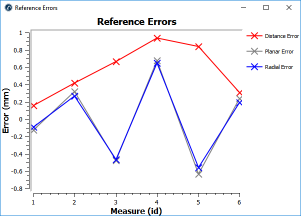
9.Select Show Errors to display the error level at each point (the distance errors are equivalent to the planar errors and the radial errors combined)
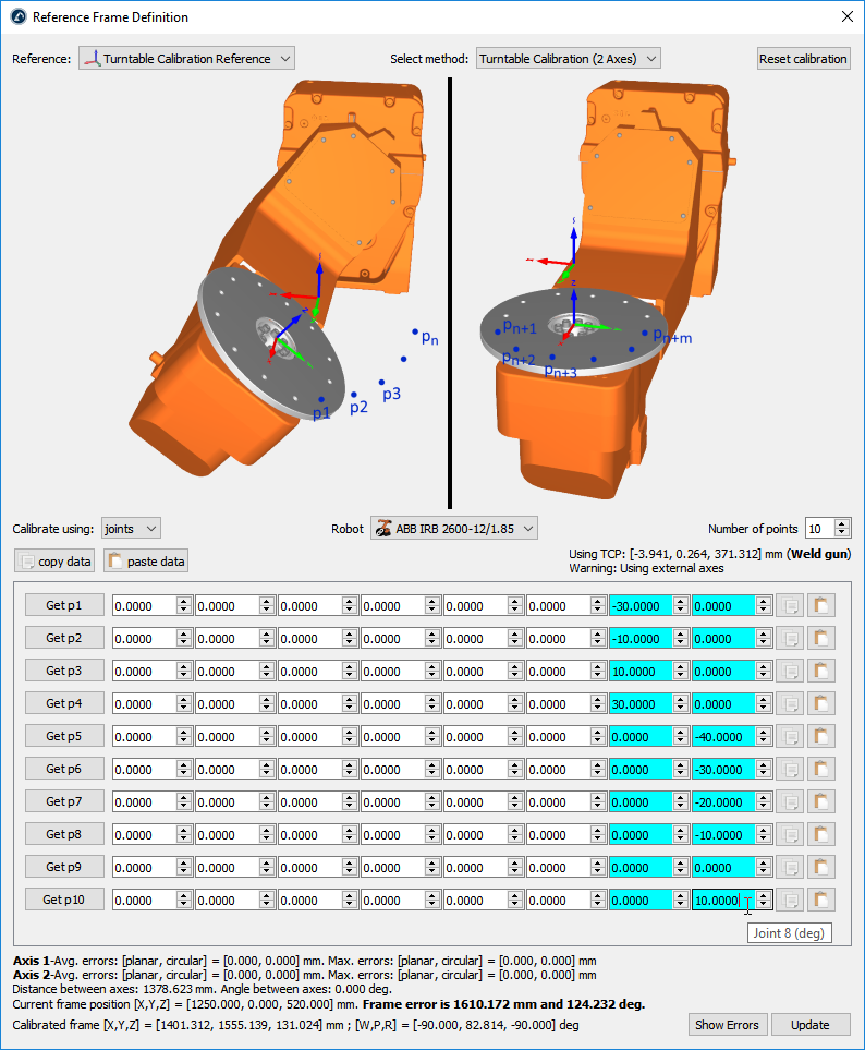
Calibrate a two-axis Turntable
This section guides you to calibrate a 2-axis turntable. You can calibrate your 2-axis turntable using a well-defined TCP and a static point on the turntable.
Follow this procedure to calibrate your 2-axis turntable.
1.Add a new coordinate system attached to the robot called Calibrated Frame: right click on the robot base and select Add Reference Frame. Then, press F2 to rename it accordingly.
2.Place the base of the turntable attached to the Calibrate Frame as shown in the attached image: you can right click on the turntable base frame and click on Change Support, then, select the Calibrated Frame reference.
3.Richt click on the Calibrated Frame and select Define Reference Frame.
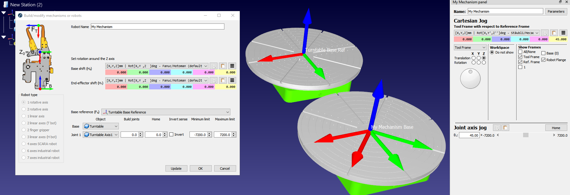
4.Select the method Turntable Calibration (2 Axes)
5.Select Calibrate using joints (default setting). You can change it to points (instead of joints) if you have the XYZ position of each point with respect to the robot base frame.
6.Specify the robot if more than one robot is available in the station.
7.Select the number of points you would like to take (the minimum required is 6 points: 3 points for each axis).
8.Start filling the table with the robot joint positions (or points).
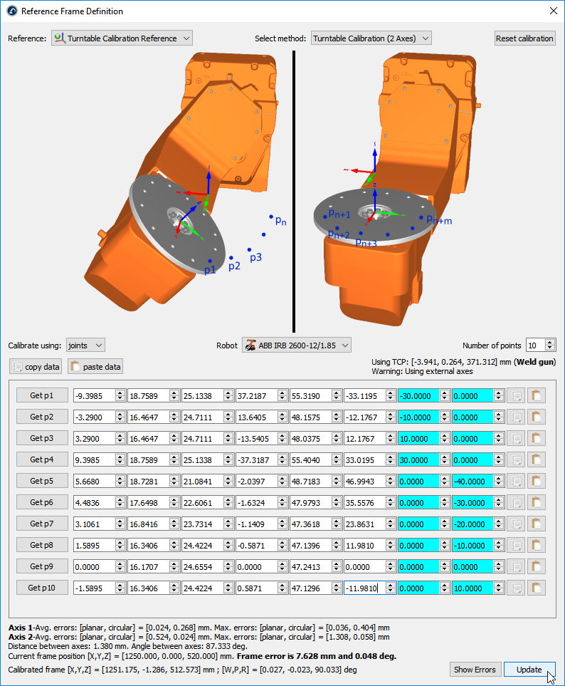
9.Finally, select Update to apply the new position to the reference frame selected in the RoboDK Station.
10.Select Show Errors to display the error level at each point (the distance errors are equivalent to the planar errors and the radial errors combined)
Importing STEP and IGES files
STEP and IGES files are two formats supported by RoboDK. STEP and IGES files are parametric 3D files. Other formats are also supported.
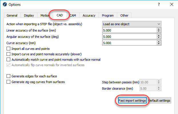
Importing STEP or IGES files can take a long time if the file is large or complex. In this case, it is possible to reduce the time it takes to import these files in the Tools➔Options➔CAD menu and select Fast Import Settings.
This option will update the default settings to import these parametric files much faster. On the other hand, curve edges will not be imported, and the accuracy of the surfaces might not be as smooth.
More information available regarding import settings in the CAD menu.
Simplify Mesh
You can always simplify your object’s mesh by grouping it if it is taking too much processing power. This greatly increases your project’s performance without compromising the visuals. To do so, press SHIFT+T or double-click your object, select “More options”, then “Change Colors”. You can then select the color/mesh you want to simplify, right-click on it, and choose “Group mesh”.

Display Performance
If you work with large 3D models or a complex project you may experience a low frame rate or slow display performance.
This can happen if you have a lot of objects or complex geometry in your station. Importing large 3D files can reduce the frame rate and slow down your simulations (see the previous section).
You can follow one or more of the following steps to improve the simulation speed and have a faster frame rate:
a)If you load 3D models using STEP or IGES files you can reduce the tolerance in the menu Tools➔Options➔CAD before loading the objects in RoboDK. You can click on Fast import settings to import files faster and with less detail. This will create lighter models and smaller RDK project files.
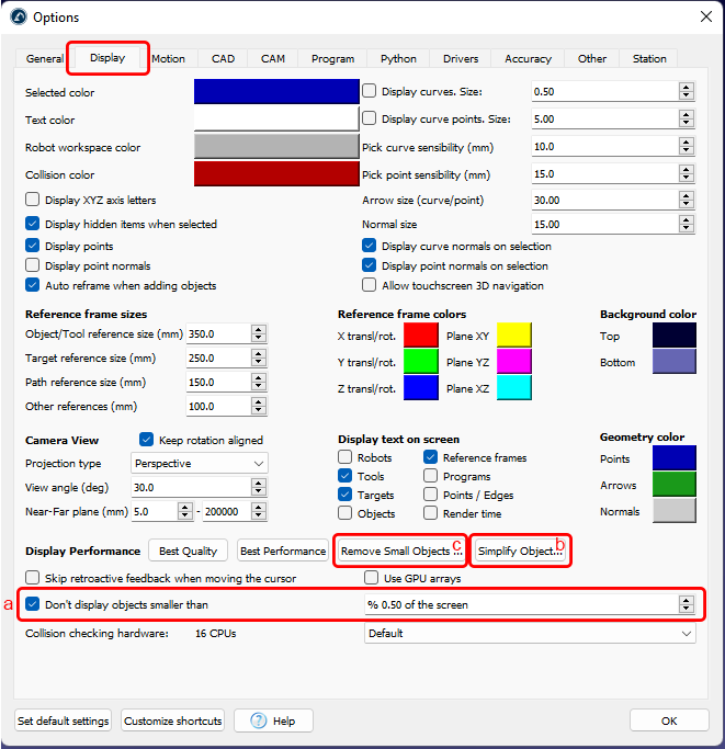
b)Ignore displaying small objects: Select Tools➔Options➔Display and check the option “Don’t display objects smaller than” and set it to 2% or greater.
c)You can use the simplify mesh Add-in to simplify objects in RoboDK. When you select an object to simplify it will reduce the size by 80%.
d)Simplify object geometry: Select Simplify Object… in the same Display tab. This action does not alter the appearance of 3D objects. Selecting the root of the station (the first item) will apply the simplification to all objects in the station.
e)Remove small objects: Select Remove Small Objects… to remove small objects and triangles. This will delete the objects and triangles smaller than a given size.

Export simulation
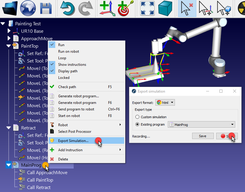
Once you have a simulation/program ready in RoboDK you can easily export it as a shareable RoboDK for Web link, as a 3D HTML or 3D PDF.
You can generate RoboDK for Web public links, 3D HTML and 3D PDF documents following these steps:
1.Right click your program (Main Program in this example)
2.Select 
3.Select Start. The program will start, and the simulation will record until the program is completed.
Save the file. After the file is saved it will be automatically opened and you can preview the result.
Export to RoboDK for Web
You can easily export your project as a shareable RoboDK for Web link. The link will be unique and available by anyone who has access to the link.
When you export your project, you’ll obtain a link to access a dashboard to manage exported links.
The following links are examples of exported RoboDK for Web links:
●Example of an exported RoboDK project: https://web.robodk.com/lnk/35303930233736
●Open this link https://robodk.com/example/Assembly-and-Palletizing-with-ABB-and-Fanuc and select Toggle 3D view.
●You can select details on any example of the stations library and select Toggle 3D View to preview the project in RoboDK for Web.
Export simulation to 3D HTML simulation
You can export your project as a 3D HTML simulation in one single file. Compressing an HTML file will remarkably reduce its size and you can send it by email.
The following links are examples of 3D HTML simulations:
●https://robodk.com/simulations/UR-Paint.html
●https://robodk.com/simulations/Welding-3-Fanuc-Robots.html
●https://robodk.com/simulations/Robot-Drawing.html
Export simulation to 3D PDF
You can export your simulation or a program as a 3D PDF document. Exported PDF documents should be opened using Acrobat Reader (not a browser).
The following links show examples of 3D PDF simulations:
●https://robodk.com/simulations/UR-Paint.pdf
●https://robodk.com/simulations/Welding-3-Fanuc-Robots.pdf
●https://robodk.com/simulations/Milling-with-External-Axes.pdf
Export simulation to Blender
You can export your simulation as a Blender project using the Blender Export add-in.
Simulation Speed
The simulation speed (or the simulation ratio) is how fast RoboDK simulates a real motion. A simulation ratio of 1 means that a movement that takes 1 second on a real robot will take 1 second to simulate.
RoboDK simulates 5 times faster than real time by default. That means that a program that takes 5 seconds to execute on the real robot it will be simulated in 1 second. Speeding up the simulation increases this ratio to 100. Normal and fast simulation speeds can be changed in the Tools➔Options➔Motion menu.

Cycle Time
RoboDK can provide cycle time estimates when you simulate a program. The cycle time is the time that it takes for a program to complete. The accuracy of the cycle time provided by RoboDK highly depends on many factors, including the robot controller, the type of robot movements (joint vs. linear movements), the use rounding and the real speed/acceleration limitations.
Under the right circumstances, RoboDK can accurately calculate the cycle time. This happens when you program the robot to make accurate point to point movements (without rounding) and you do not exceed the real speed and acceleration limitations.
The robot speed and acceleration are important as they are robot dependent. The robot speed and accelerations (linear and joint speed/acceleration) must be provided as an instruction or in the robot parameters menu. For example, you can change the speed in a program using the Set Speed Instruction. RoboDK assumes that the robot has a uniform acceleration up to when it reaches the maximum speed, then, uniform deceleration.
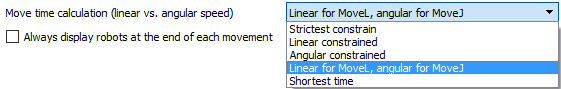
By default, RoboDK uses joint speed and joint acceleration for joint moves and linear speed and linear acceleration for linear moves. This setting can be changed (in Tools➔Options➔Motion➔Move time calculation).
Change Color tool
You can change the color of your objects in RoboDK by using the Change Color tool.
Follow these steps to change the color of your robot:
1.Select Tools ➔Change Color.
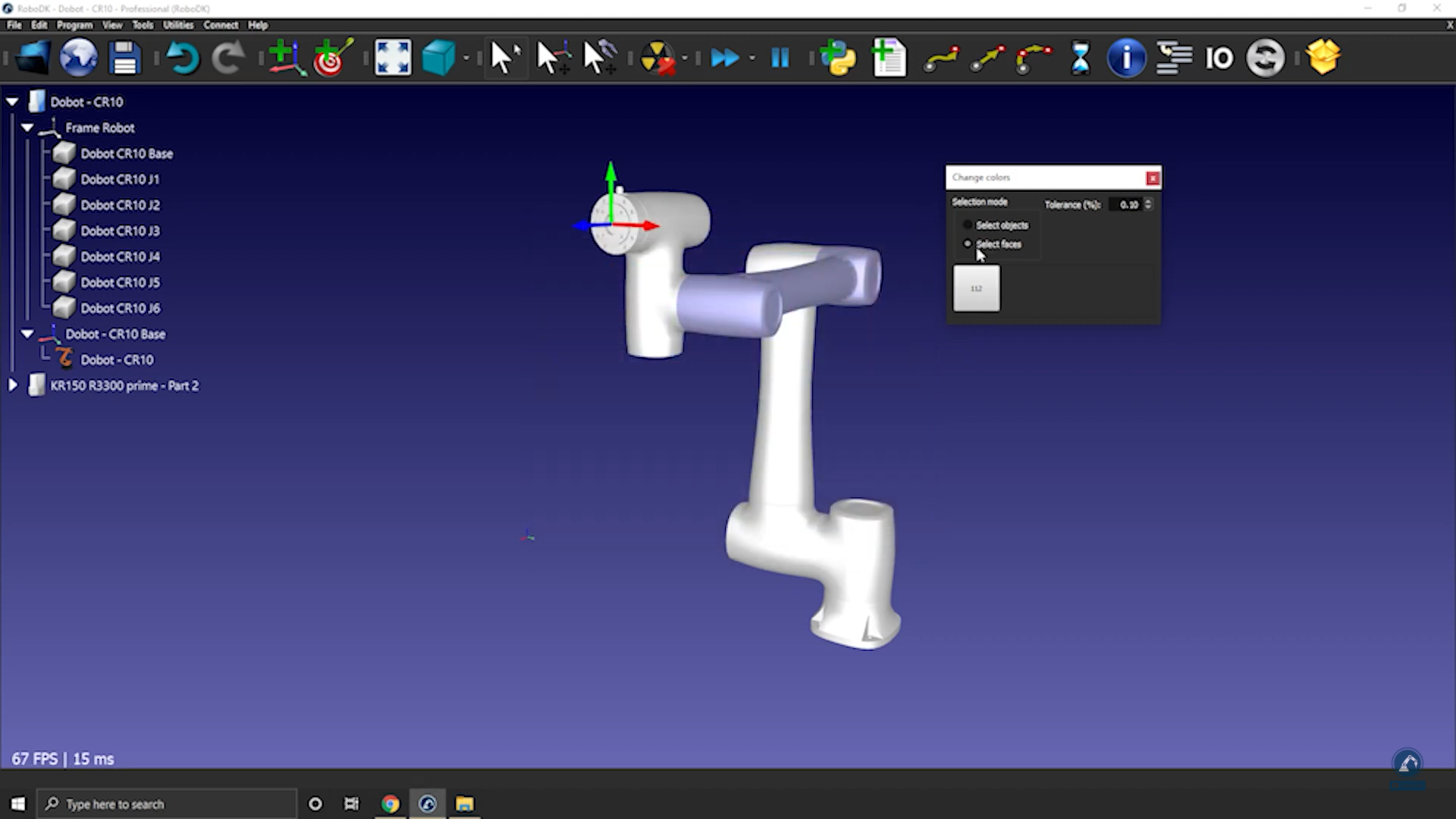
2.By selecting the 3D model, you will be able to see the actual color of the robot.
3.Select Select Faces in the Change Color window and then select the faces that you wish to change colors.
4.Once you have selected the faces, click the color, and select a new color.
Measure tool
By using RoboDK’s measure tool you can measure the distance between different geometric features, such as cylinders and planes, and extract their properties.
Select Tools➔ Measure to open the measure tool. You can then select geometric features in the 3D window.
Create a Mechanism or a Robot
You can model new mechanisms with RoboDK, this includes turntables, one to three linear axis mechanisms, different types of robot arms, Scara robots, AGVs, CNCs and grippers.
Following these steps to create a new robot or mechanism:
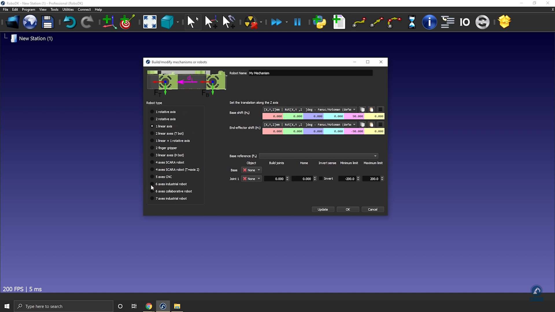
1.Select Utilities➔Model Mechanism or robot.
2.Select the type of mechanism or robot you want to create.
3.Select the coordinate system that represents the origin of your mechanism.
4.Select one object for each joint (moving part of the mechanism or robot).
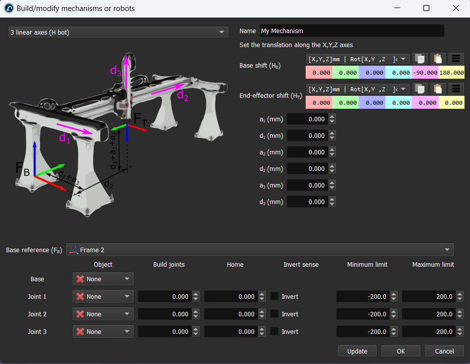
5.Enter the robot parameters as described in the corresponding image.
6.Select Update to see the new mechanism.
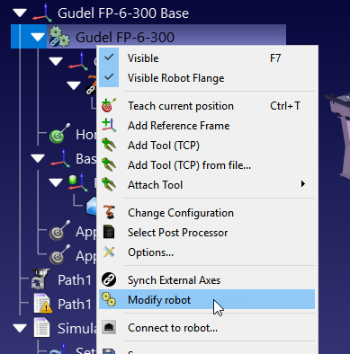
You can also modify existing mechanisms by right clicking the robot item in the tree and selecting Modify robot. This option is available for robots and mechanisms that you created yourself.
You can create the following types of mechanisms and robots in RoboDK:
●One rotative axis (a turntable or a gripper)
●Two rotative axes (for example: a 2-axis positioner)
●One linear axis (such as a linear rail)
●Two linear axes (such as a T-bot)
●Three linear axes (such as an H-bot)
●One linear axis + one rotative axis
●Two-finger grippers
●Scara robots (4-axis)
●Six-axis robot arms
●Seven-axis robot arms
How to model a one-axis turntable
This section shows how you can model a one-axis turntable. Turntables are often used for robot machining applications.
Follow these steps to create a turntable:
1.Load the 3D models of the turntable: drag and drop 3D models to the RoboDK window (such as STL, STEP or IGES files).
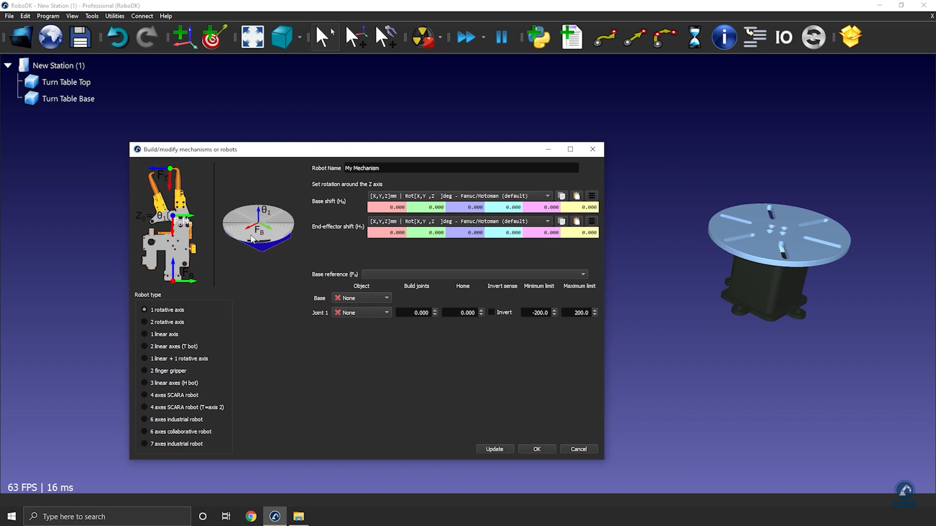
2.Select Utilities➔Model Mechanism or Robot.
3.Select 1 rotative axis.
4.If you look at the image, it should show you how the base and top plate should be positioned. In the case of a rotative axis, the mechanism will rotate around the Z axis of Fb (Frame Base)
5.Rename your mechanism to TurnTable.
Define the reference of your turntable by creating a new coordinate system:
1.Create a reference frame and select F2 to name it to Frame Base.
2.Modify the position of the frame by opening Frame Panel.
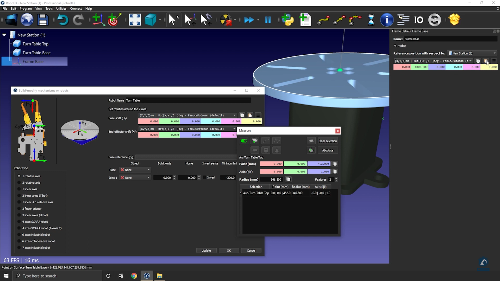
3.Select Tools and then Measurement.
4.Measure the position of the surface by clicking on the mechanism; You can see the difference between the origin and the center. You can copy the values and paste them as shown in the image below.
The reference position should now match the reference in the image. The reference frame and the object items should be automatically populated. If the automatic selection is not correct you can update it accordingly.
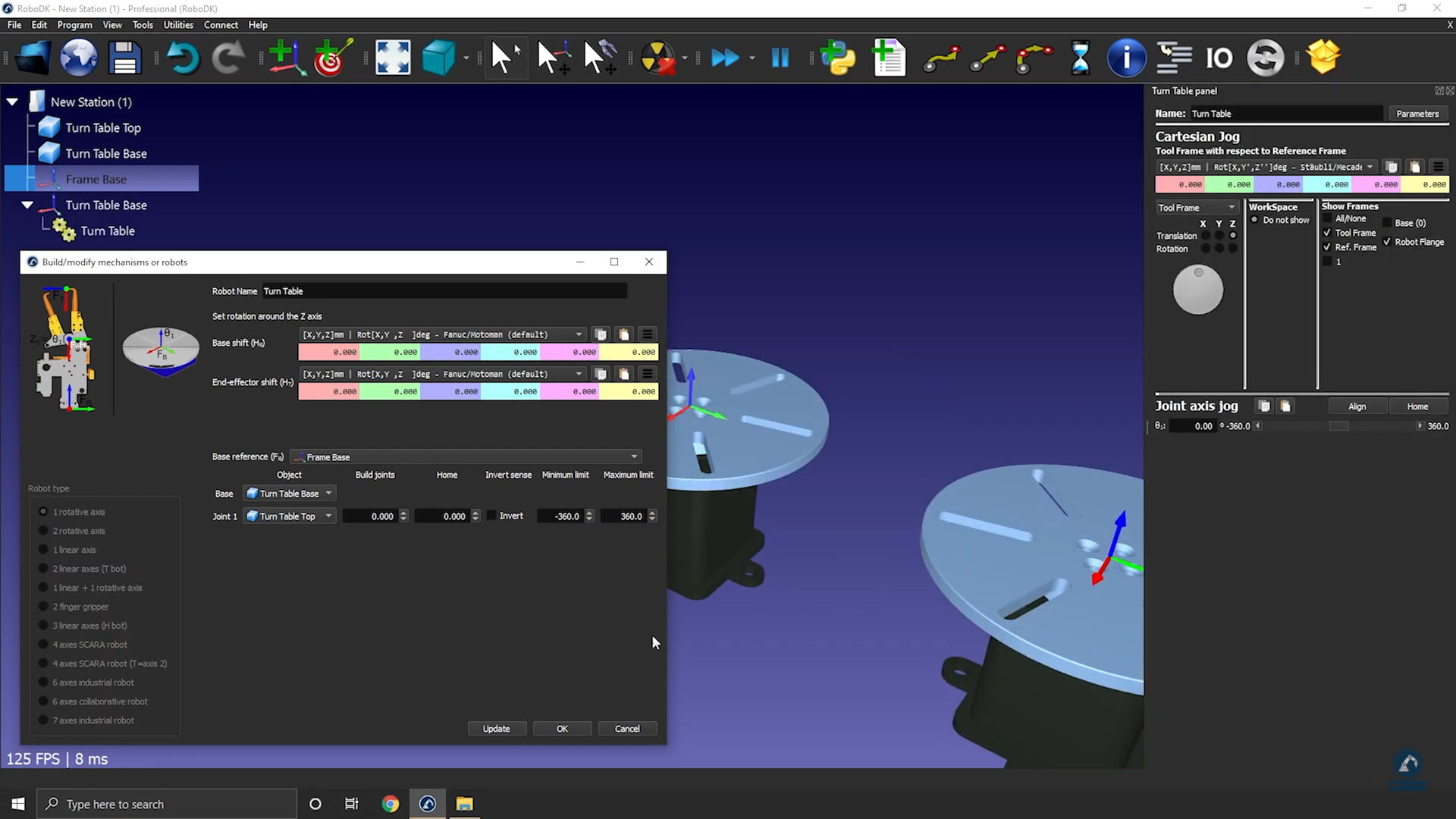
6.You can update the joint limits, for example, if we want to have +/-20 turns we can enter +/-7200 deg. You can also change the joint limits later by double clicking the joint limit labels of the robot panel.
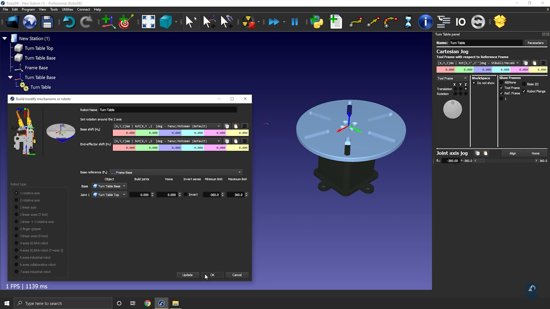
7.Select Update to generate the mechanism: the new mechanism will appear.
8.You can select OK to close the menu or add additional changes to your turntable if required.
9.You can delete the original object files you used to create the mechanism. The mechanism will be saved with your RDK project, and it does not require any external dependencies.
10.Once you have tested your table (make sure that it is moving in the right direction and that the limits are what you were expecting), you can select OK on the Model mechanism window to close it.
How to model a one-axis linear rail
This section shows how to model a 1-axis linear rail, also known as a linear axis or linear track. A linear rail helps extending the reach of robot arms.
Follow these steps to import your 3D model:
1.Drag and drop your 3D model in RoboDK to import the objects into your station (accepted file formats include STEP, IGES or STL are common 3D formats).
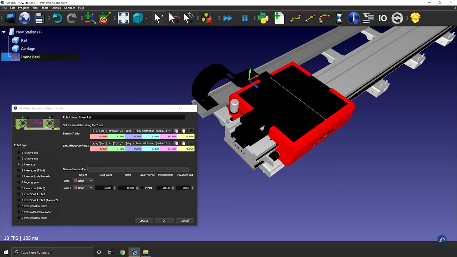
Follow these steps to open your mechanism builder:
2.Select Utilities ➔Model Mechanism or Robot.
3.Make sure 1 linear axis is selected under “Robot Type”.
4.If your 3D model is grouped in one piece, you can split your model inside of RoboDK.
Follow these steps to position your base frame:
5.Now that you have the objects loaded, open your model mechanism builder again Utilities ➔Model Mechanism or Robot.
6.You can rename your mechanism under Robot Name.
7.Consider that your base frame should be at the 0 position of the rail: Create a reference frame there and name it Frame Base.
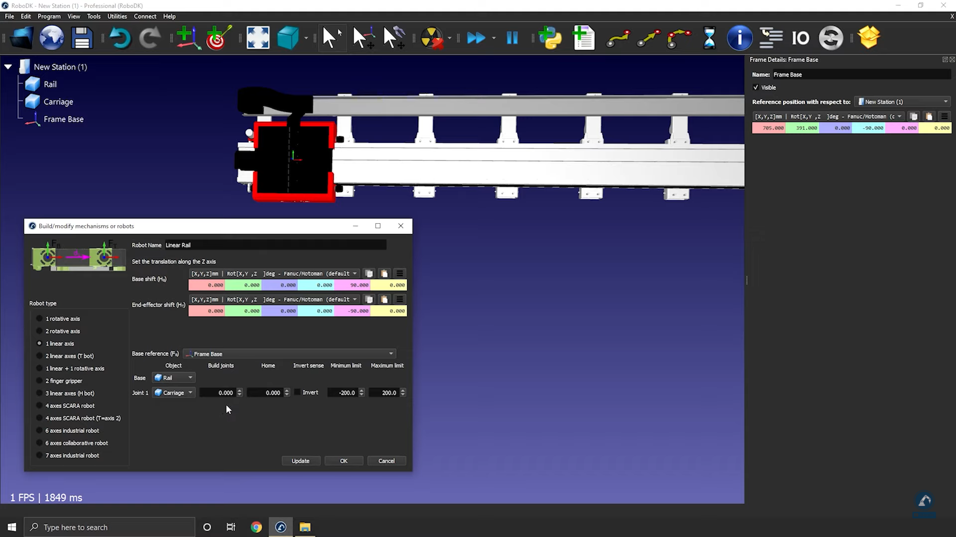
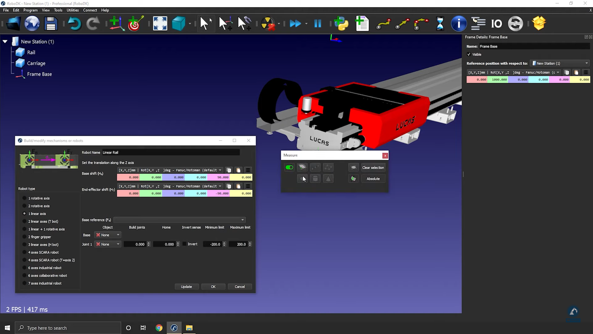
Follow these steps to modify the position of the frame:
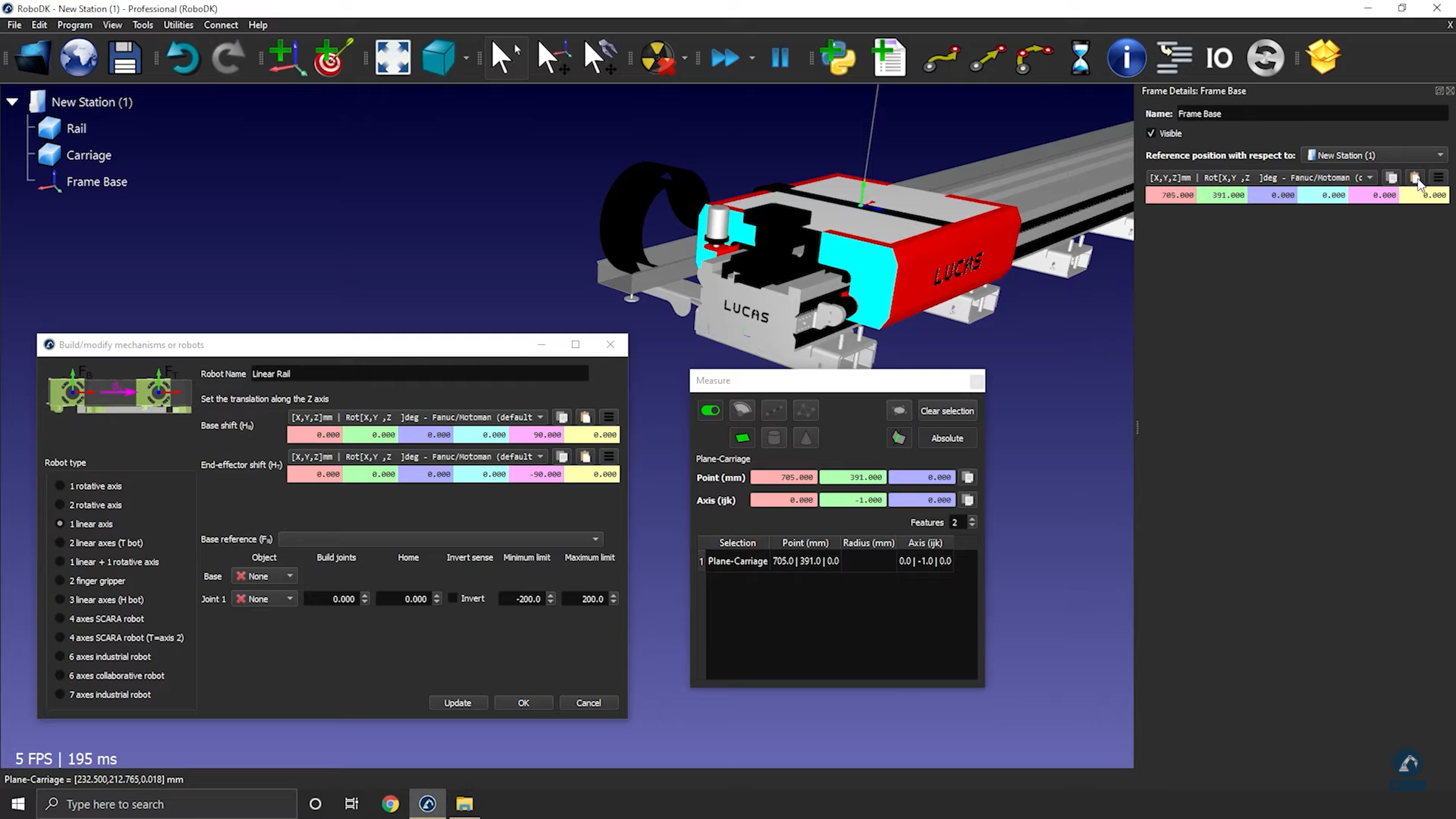
8.Select Tools ➔ Measure.
9.Use the measure tool to measure the position of the surface by selecting the icon (as shown in the image below).
10.Copy the values and paste under Frame Details: Frame Base (as shown in the image below).
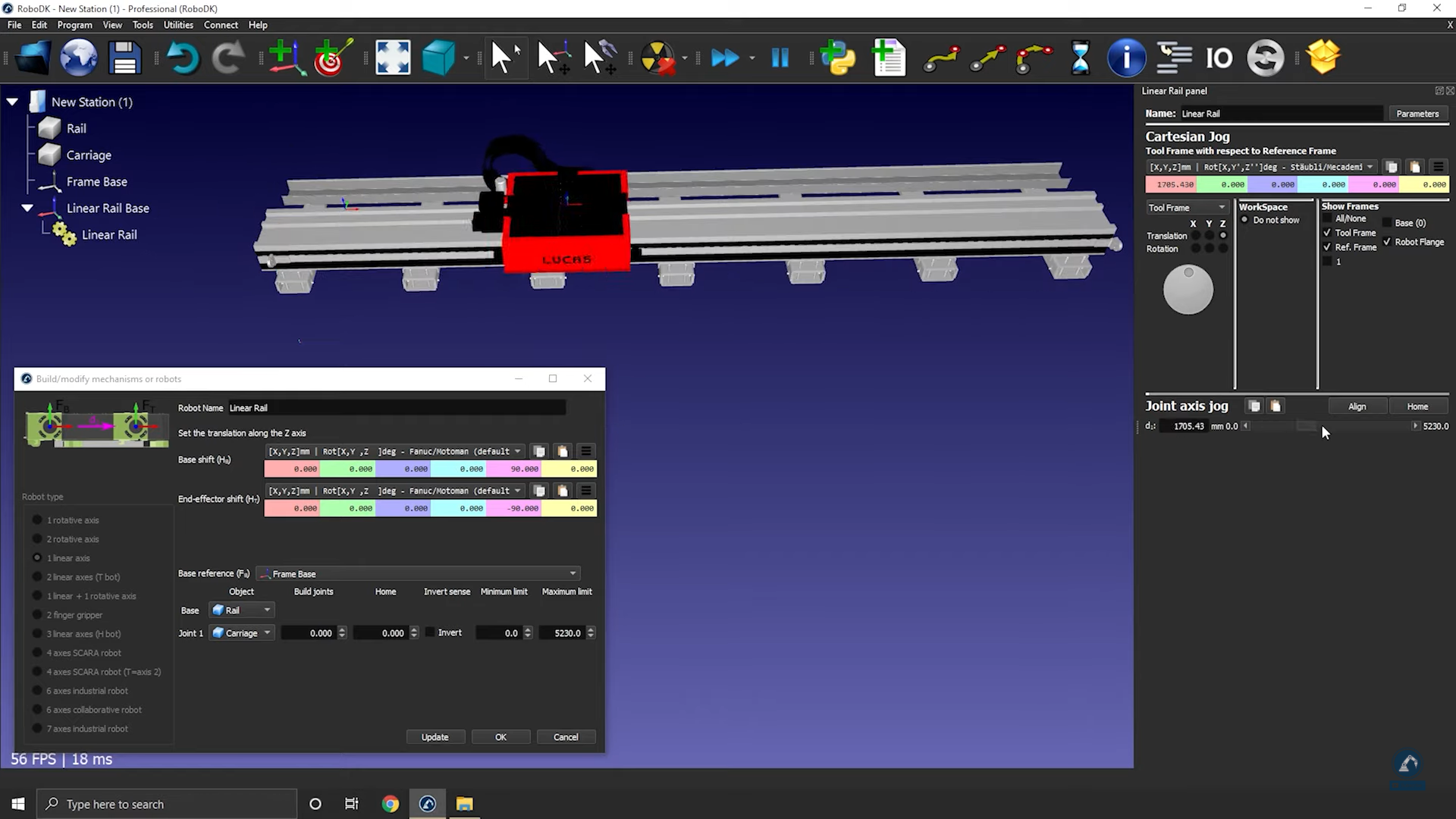
Follow these steps to check orientations and to enter the rail length:
11.Rotate clockwise, 90 degrees around X: Enter the value -90.000 degrees in the reference position window.
12. Enter the length of the rail in the model mechanism window (as shown in the image below).
13.Select Update to create the robot.
14.You can test the rail (make sure that the limits are good and that it is moving in the correct direction) by using the joint axis jog.
15.Select OK when you are satisfied with the results.
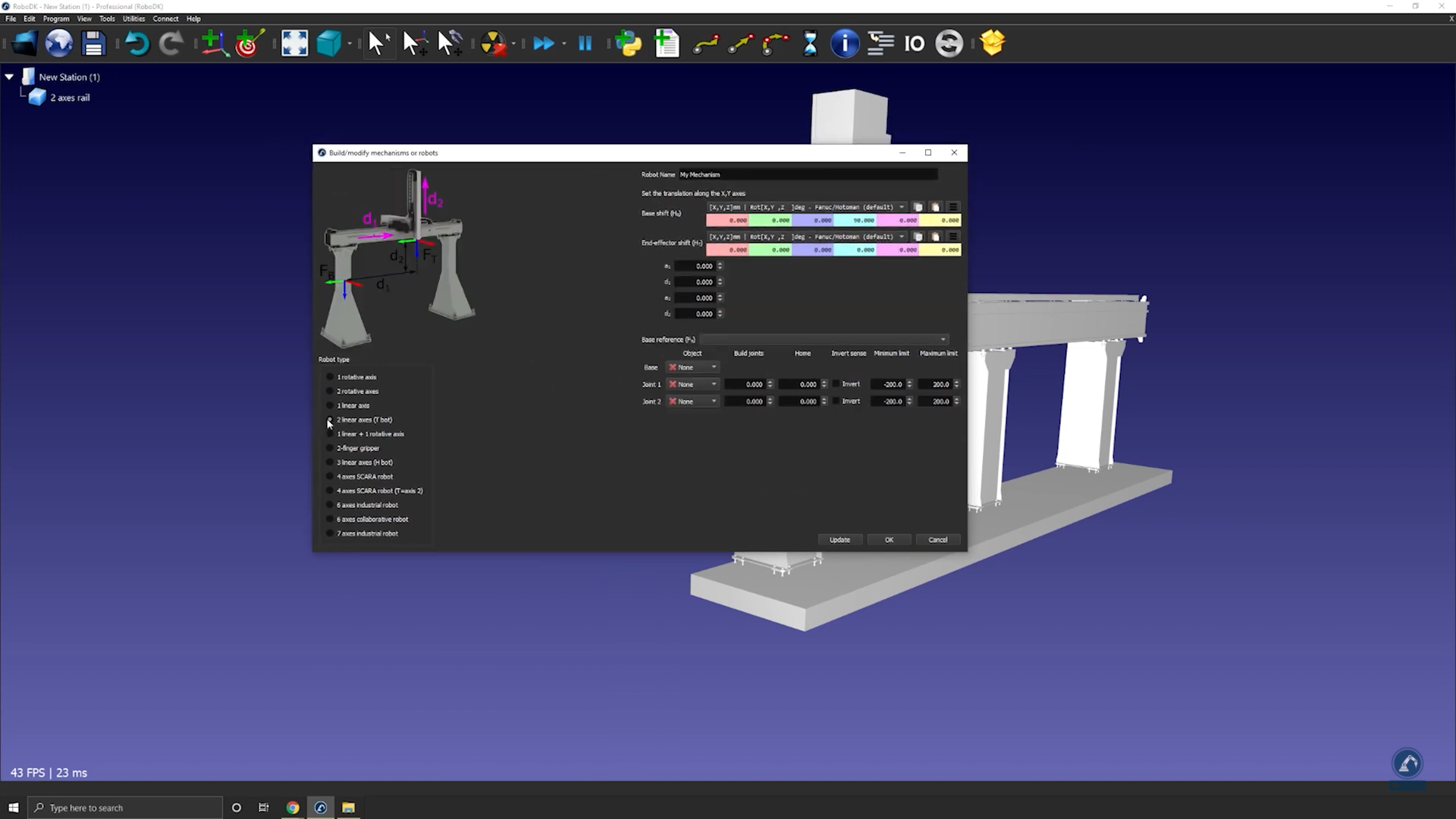
How to model a two-axis linear rail
This example shows how to model a 2-axis linear rail, also known as a linear axes or linear track. Linear axes are used to extend the reach of robot arms.
Follow these steps to set up your 3D model in RoboDK:
1.Import your 3D model into RoboDK ➔ drag and drop the STEP file into your station.
2.Open the Mechanism builder: Utilities ➔ Model Mechanism or Robot.
3.Under Robot Type, select 2-linear axes (T-bot).
4.Once your model is split into 3 pieces, re-open the rail builder: Select Utilities ➔ Model Mechanism or Robot.
5.Select the option: 2-linear axes (T-bot).
6.Rename your robot to T-bot (under robot name).
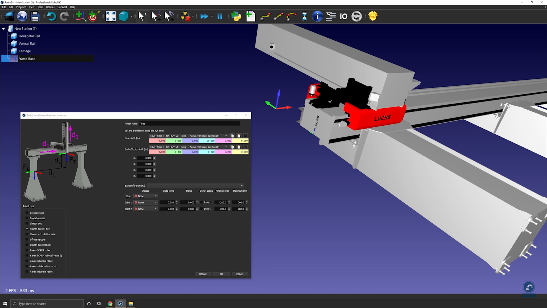
Follow these steps to find the location of your base frame:
7.If you consider that your base frame should be at the 0 position of the rail, create your reference frame exactly there and rename it to Frame Base.
Follow these steps to modify the position of the frame:
8.Open the frame panel by double clicking the frame.
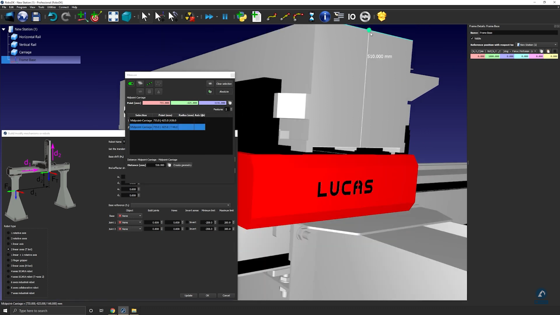
9.Measure the position of the center of the surface by opening your measurement tool: Tools ➔Measure.
10.Select the center point of each edge (as shown below) to find the distance between the two lines.
11.Select Create Geometry in the Measure window which will create a line between the two points.
12.Select Clear Selection.
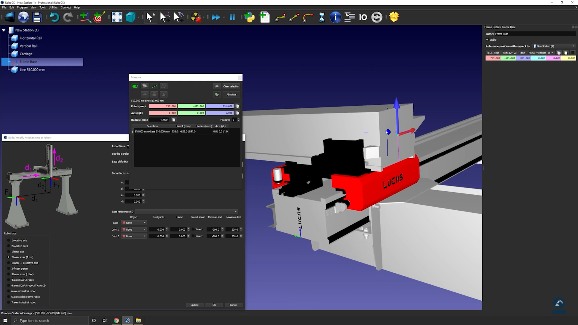
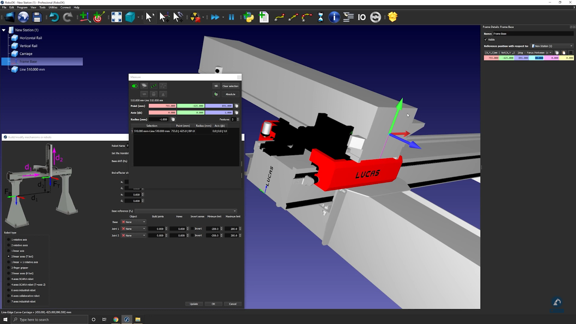
Follow these steps to measure the position of the center point between the two lines:
13. Select the center point of the line.
14.Copy the values in the Measurement window and paste the values as the frame position (as shown below).
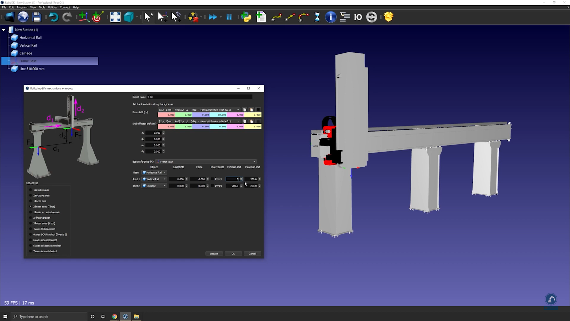
Follow these steps to make sure the orientations are the same:
15.Rotate counterclockwise, 90 degrees, around X and then rotate 90 degrees around the Z axis (as shown below).
16.Enter the measurements of the rail in the Model Mechanism or Robot window as show below.
17.Select Update to create the robot.
18.If you are satisfied with the results, select Ok in the “Model Mechanism or Robot” window.
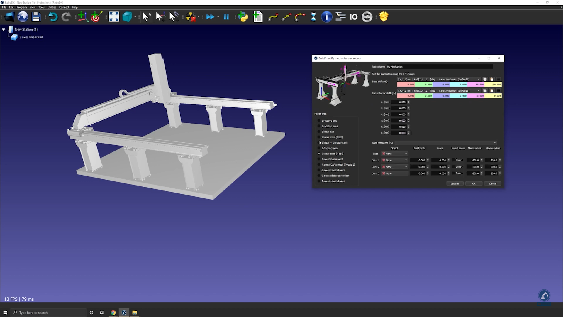
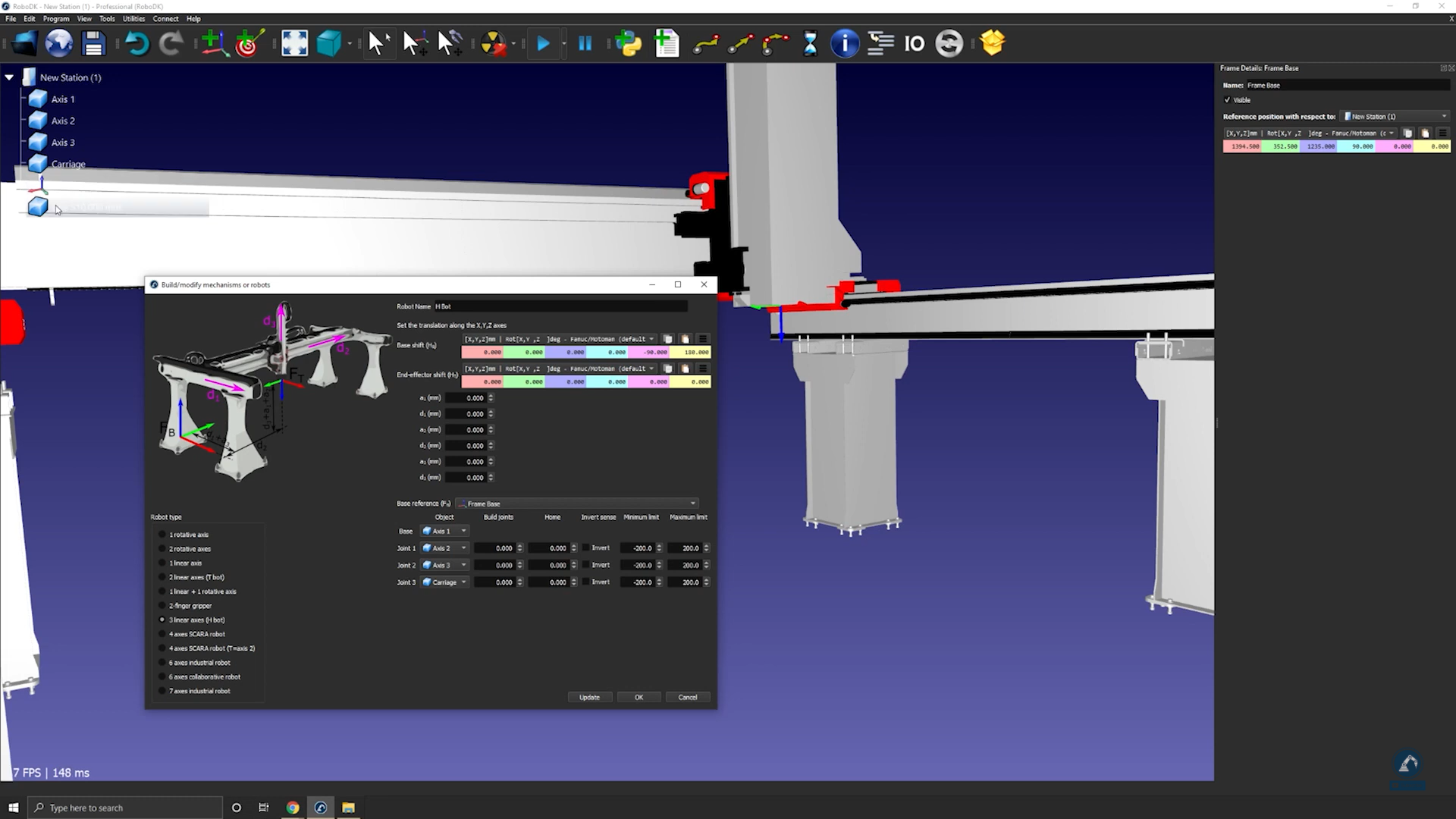
How to model a three-axis Cartesian robot
The following video shows how to model a 3-axis Cartesian robot (H-bot). Robot arms can be mounted on external axes to extend their reach.
Follow these steps to set up your 3D model in RoboDK:
1.Drag and drop the 3D model (such as a STEP or IGES file) in RoboDK to load it into your station.
2.Open the mechanism builder: select Utilities ➔Model Mechanism or Robot.
3.Under Robot Type, select 3-linear axis (H-bot).
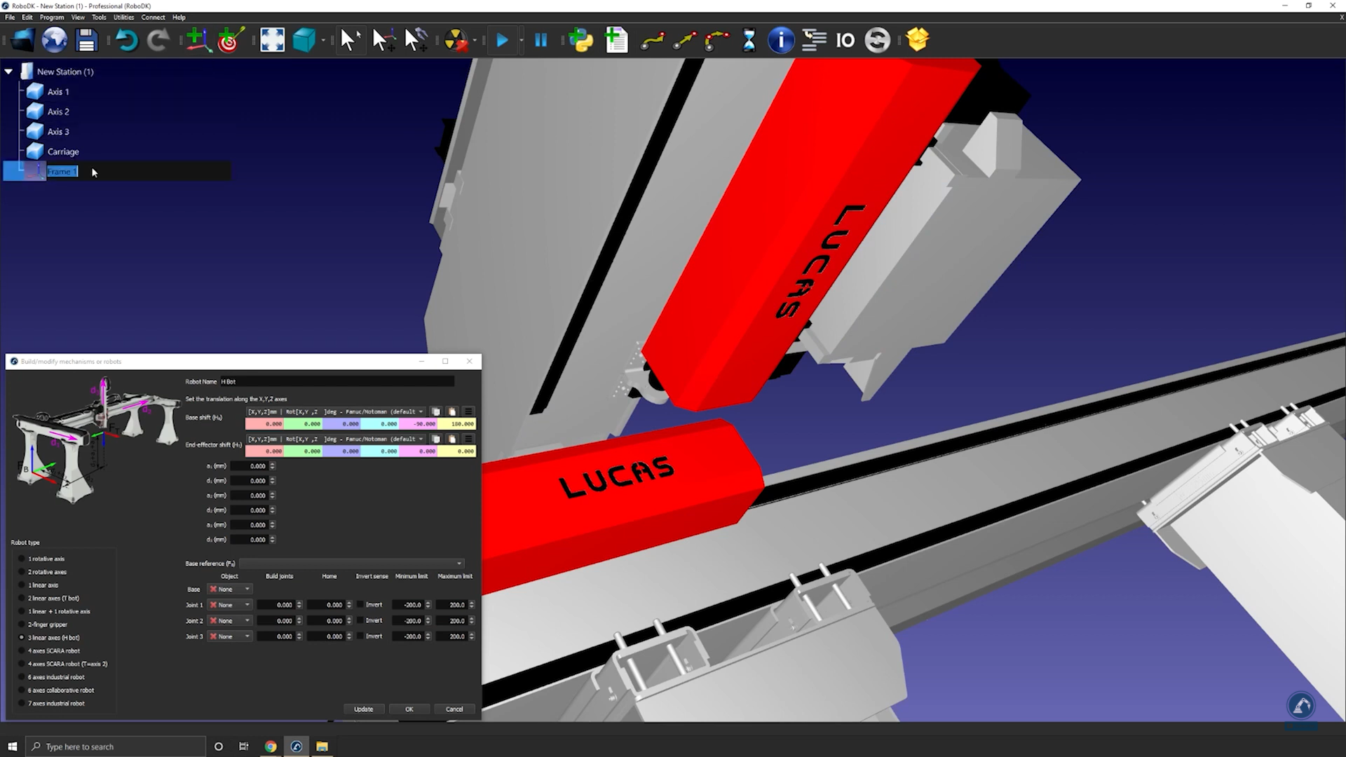
Follow these steps to create your Base Frame:
4.Once your object is split into different pieces, re-open the rail builder (select Utilities➔Model Mechanism or Robot➔3-linear axis).
5.Rename your robot under Robot Name.
6.Create a reference frame at the 0 position of the rail. You can rename it as Frame Base.
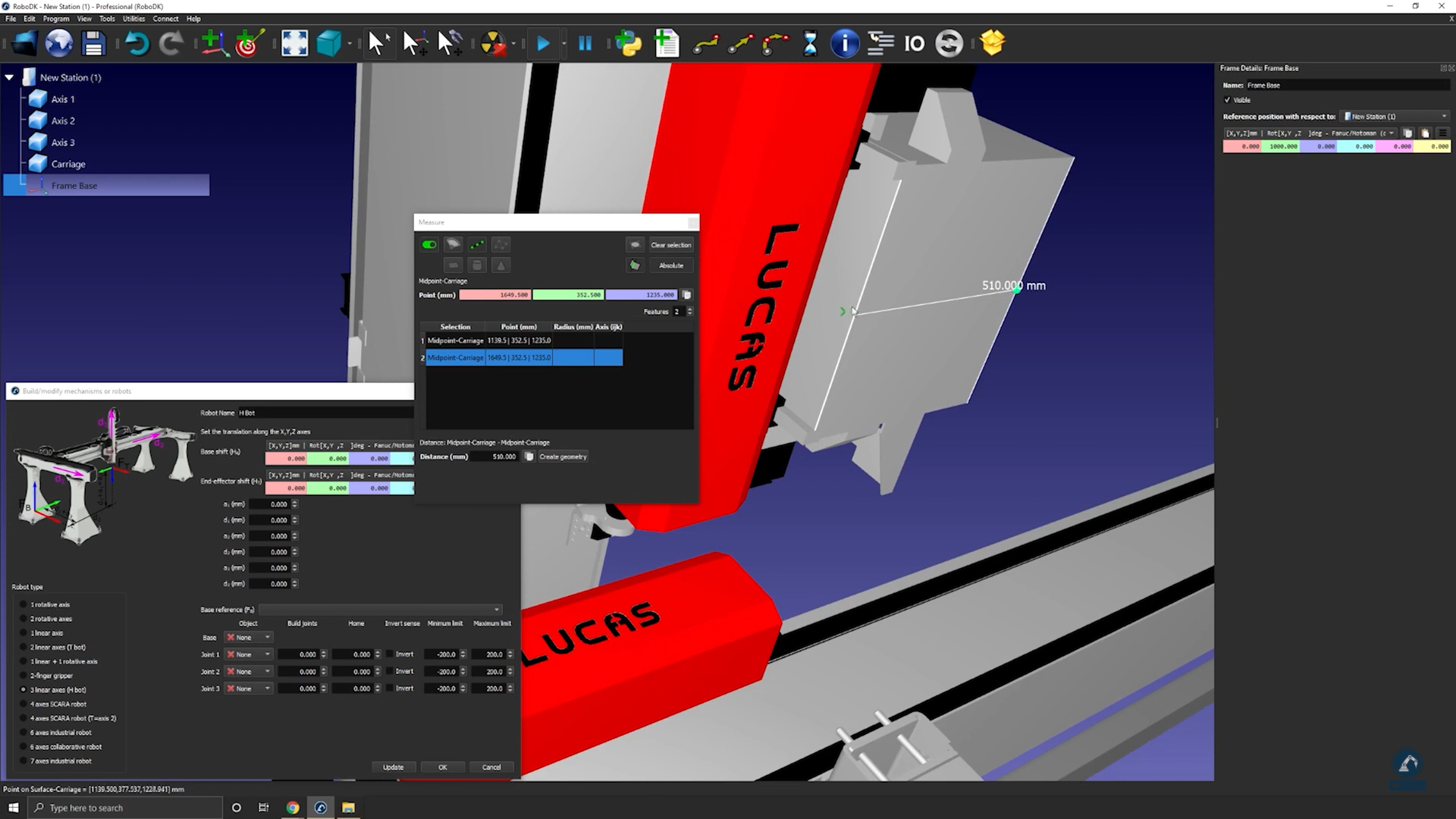
Follow these steps to modify the position of the frame:
7.Open the frame panel by double clicking “Frame Base”.
8.Open the measurement tool: Tools➔Measurement.
9.Select the icon that is highlighted below in the measurement tool and then select both edges of your object to find the distance between both center points.
10.Select Create Geometry to create a line between both center points.
11.Now that the line between both points is created, you can select Clear Selection.
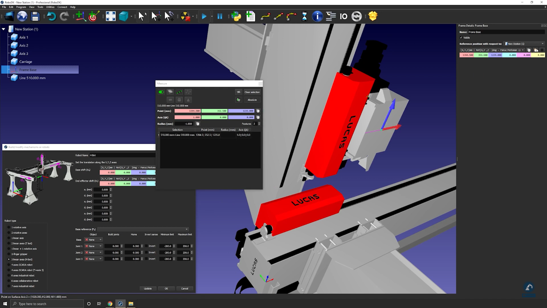
12.Select the center of the line to find the measurement of the center point of your newly created line.
13.Copy the values and paste them as the frame position (as shown in the image below) to make sure that the frame position matches with the reference image.
Follow these steps to make sure that the orientations are the same:
14.Rotate 90 degrees counterclockwise.
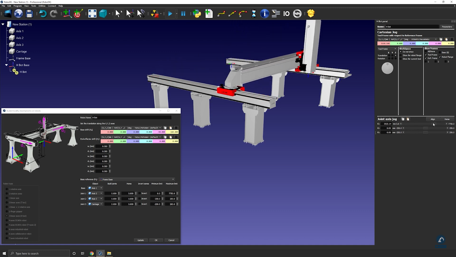
15.Select Frame Base and then select the rail 3D models (select each section one by one) as shown in the image below.
16.Enter the length of each rail in the measurement section.
17.Move each axis under Joint Axis Jog to make sure each axis is moving fine.
18.Press Update after testing each axis to create your robot.
19.If you are fine with the results, you can press Ok on the model mechanism window.
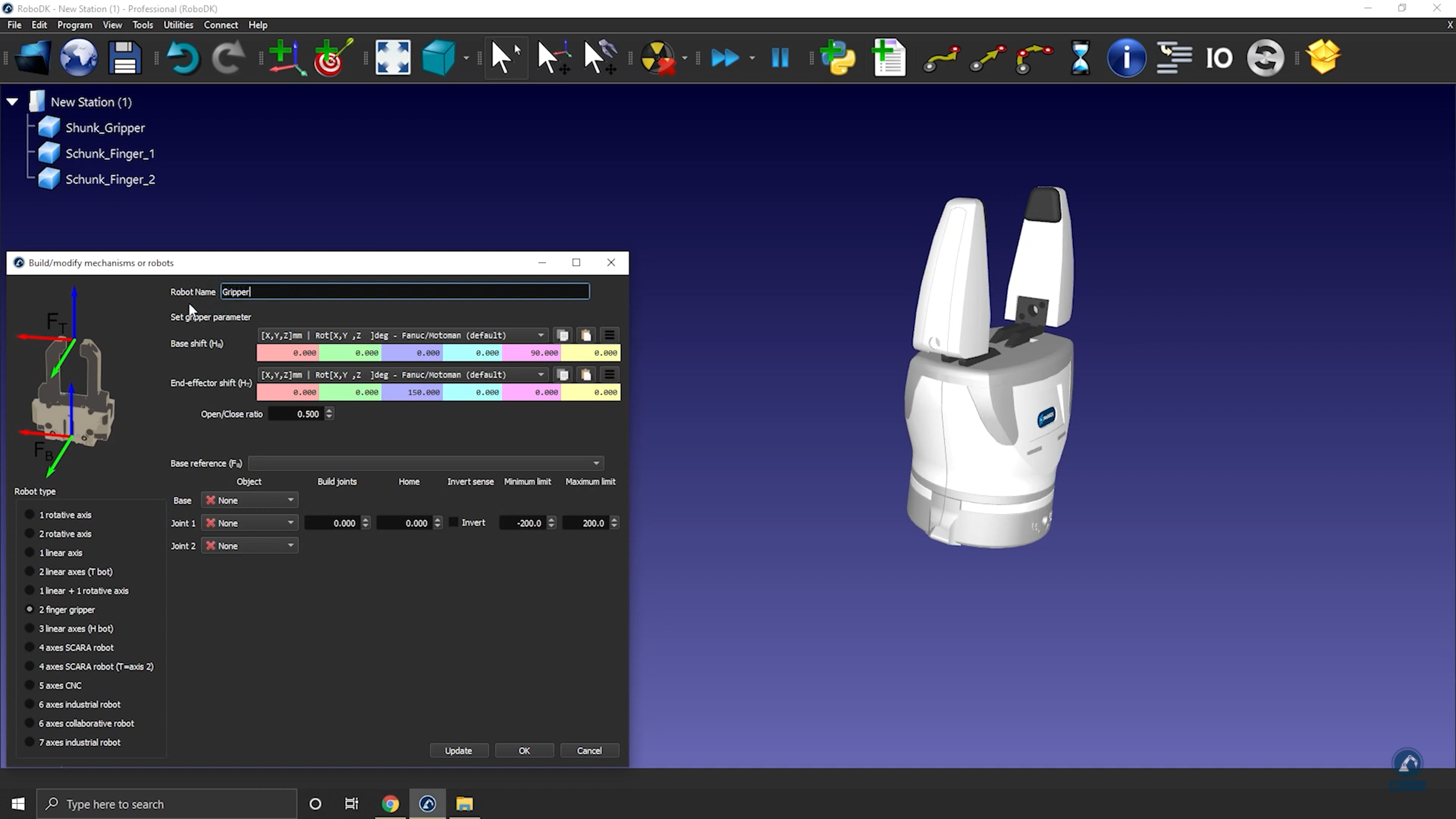
How to model a two-finger parallel gripper
You can model a parallel gripper in RoboDK by using the Model Mechanism or Robot tool. Parallel grippers are also called 2-finger grippers and allow a robot to grab parts.
Follow these steps to set up your 3D model in RoboDK:
1.Import your 3D model: Drag and drop your STEP file to load it into your station (IGES or STL files will also work).
2.Open the mechanism builder: Utilities ➔Model Mechanism or Robot.
3.Select 2 Finger Gripper under “Robot Type”.
4.You can rename your robot “Gripper”.
Follow these steps to position your base frame:
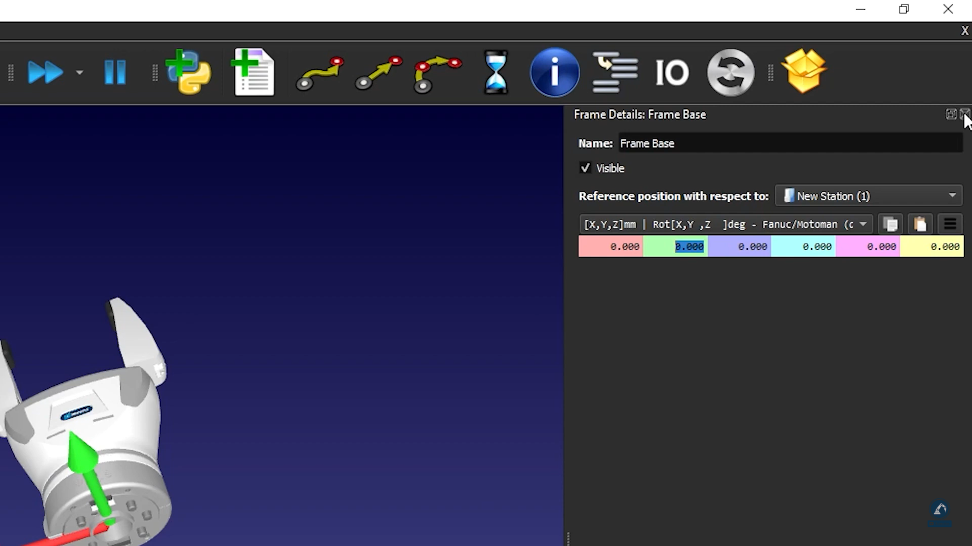
5.Create a reference frame (it should be below the gripper), and rename it as Frame Base.
6.Make sure that the frame you just created is positioned according to the image: Bring the reference frame to 0.000 mm (X,Y,Z).
7.Enter the gripper range of motion: If you put the fingers at the 0 position, the minimum limit will be 0 and the maximum limit will be 80.
8.Select Update.
9.Make sure it moves in the right direction and that the limits are good by using the Joint Axis Jog.
10.If you are fine with the results, you can press Ok.
How to model a six-axis robot arm
This example shows how to model a 6-axis industrial robot arm from scratch, using the 3D models provided by the manufacturer.
Follow these steps to gather some information about your robot:
1.Firstly, you need the 3D models (such as STEP or IGES files).
2.You will also need the robot data sheet or robot manual.
Follow these steps in RoboDK to open the robot model window:
3.Select Utilities➔Model Mechanism or Robot.
4.Under Robot Type, select 6 axis industrial robot.
Load your robot 3D files onto RoboDK by doing the following:
5.Drag and drop your robot into RoboDK or select file and then open (it may take a few seconds to load).
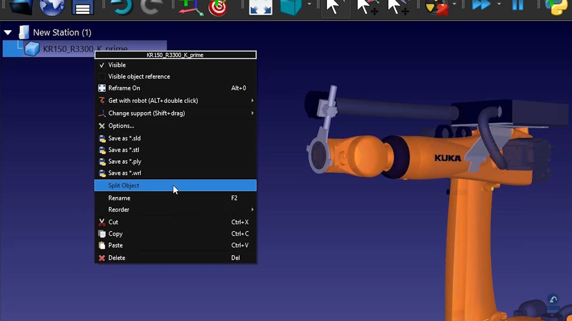
Follow these steps to split an object into different pieces so that we can treat each piece separately:
6.If the CAD file that you downloaded is in one single object, you can ungroup the object (STEP file) by right-clicking on any object and selecting Split Object.
7.You can then regroup it to create the different pieces of the robot.
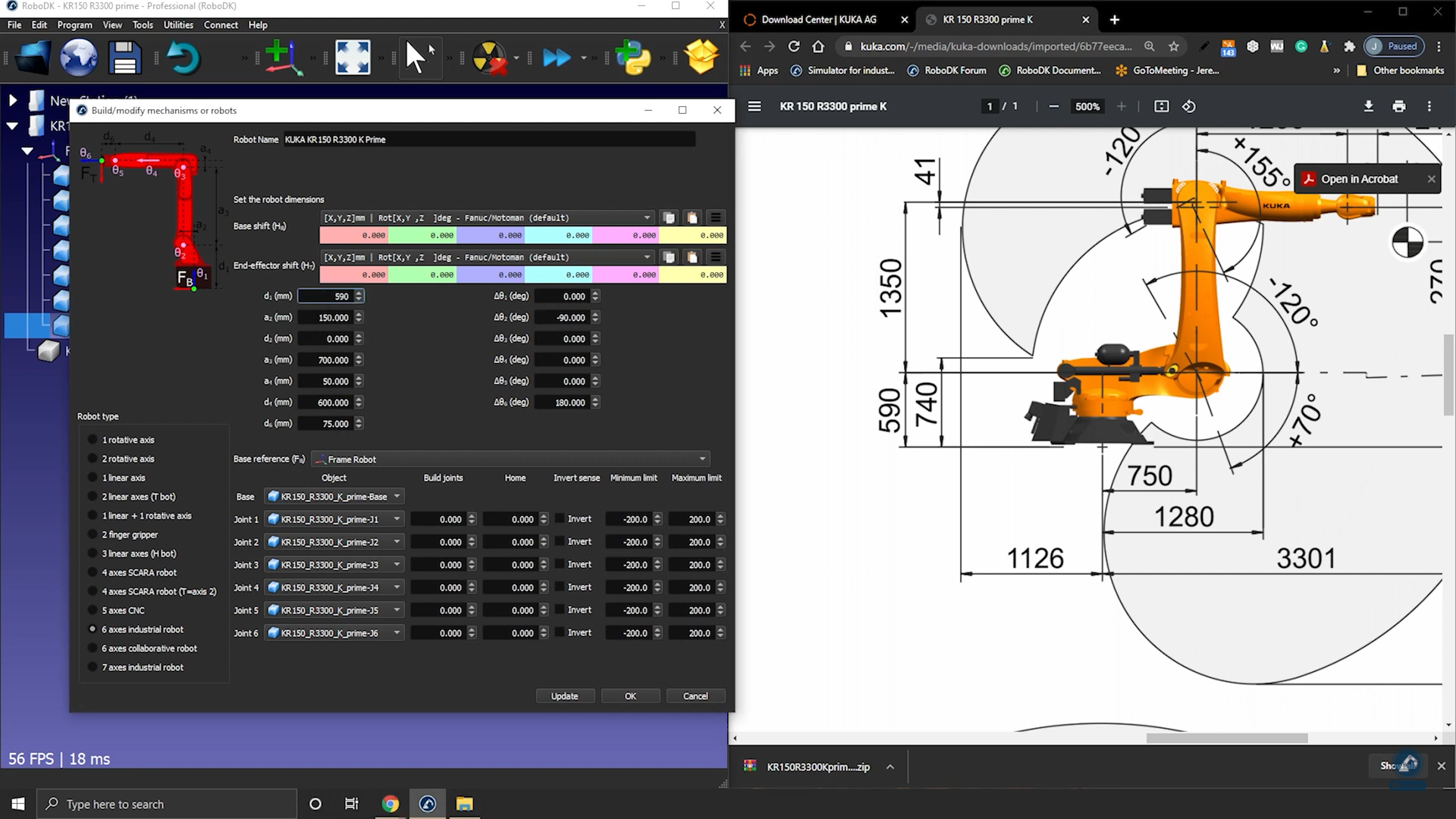
Follow these steps to enter the robot kinematics information in RoboDK:
8.Give your robot a name by entering it in Robot Name.
9.If the pieces of your robot are in the right order, then all of the 3D models should be populated correctly. Otherwise, you can manually link each object to the right robot joint.
10.Fill in the dimensions of the robot by opening the data sheet.
11.On the 3D sketch of the data sheet, you will find all the values that you are looking for. Fill in the correct values in RoboDK.

12.Once you are satisfied with the result of the robot kinematics, select Update.
How to couple robot joints together
Some robots have two joints coupled together, which means that two of the joints of the robot are dependent. For instance, Fanuc robots have joint 2 and joint 3 linked together.
Follow these steps to couple the joints of your robot in RoboDK:
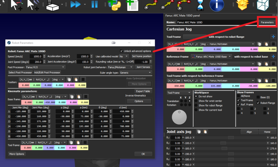
1.First, double click on the robot to open robot panel.
2.Click on Parameters to open the Robot Parameters tab.
3.Check the Unlock advanced options box.
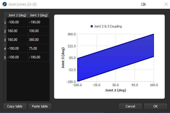
4.Click on Joint Senses to open the Joint axis sense tab. The first 6 values represent the joints turning direction and the last value is the coupling of joint 2 and 3. Change the 7th value to -1 to link the joints. A new tab with the coupling joint limit polygon will open, you can edit the limits to prevent the robot from colliding with itself.

Synchronize Additional Axes
It is possible to synchronize a robot arm with additional external axes. External axes can be simply used as a positioner or they can also be synchronized with the same robot controller. When external axes are synchronized, the robot and the axes can move at the same time while keeping accurate linear movements relative to a coordinate system.
You can synchronize up to 6 additional axes with any robot using RoboDK. If you are using a 6-axis robot this means you can have a combined system with 12 axes.
To synchronize a robot arm with external axes:
1.Load your additional axis from our library or model it as a new mechanism.
2.Build a RoboDK station placing the robot and axes/mechanisms in their location.
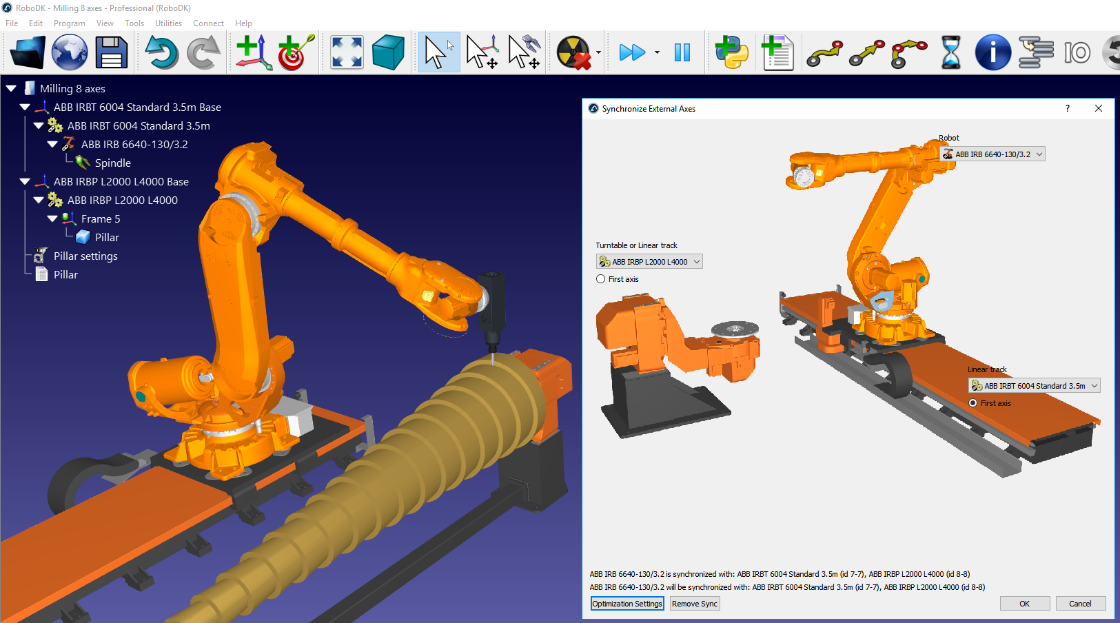
3.Select Utilities➔Synchronize External Axes.
4.Select the robot and the available turntable and/or linear track will be available to synchronize with the robot.
5.Select OK. A new robot panel will open showing the additional axes in blue.
Targets related to this synchronized robot will show additional joint values in blue. It is possible to specify the preferred position of a positioner when a program is generated. Cartesian targets will keep the provided Cartesian position while moving the external axes along the path.
Any robot machining settings will show additional options to provide the preferred position of the external axes. Also, each movement exported through the post processor will include the position of the external axes.
Optimize External Axes
When you have one or more additional axes synchronized with your robot you can prioritize moving certain axes and optimize your robot machining projects, curve/point follow projects and 3D printing projects according to your preferred criteria.
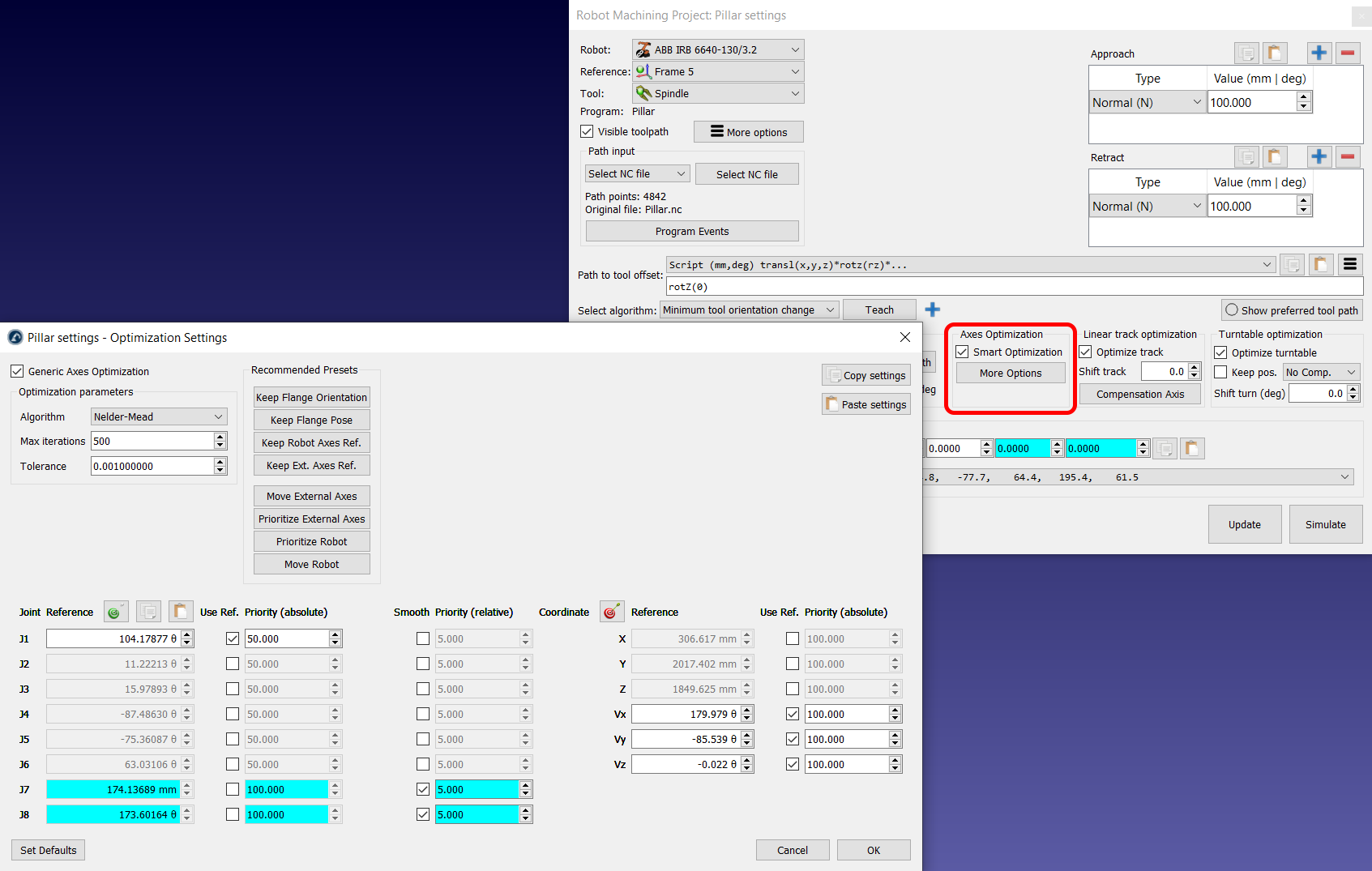
Select More Options in the Axes Optimization section of your robot machining project to see the external axes optimization options.

You can provide different priority according to the following criteria:
●Maintain reference joints: You can impose a desired axis position for some (or all) joints. A higher weight means it is more likely to match the reference value anytime during the program.
●Minimize motion (match previous position): You can impose a “penalty” to moving certain axes abruptly (relative motion).
●Maintain reference pose: You can impose a desired absolute robot pose to maintain. The reference pose is the pose of the robot flange with you want to maintain with respect to the static robot base. The orientation constrain will try to match the X, Y, Z vectors of the robot flange pose according to the reference pose.
For example, if you select the Keep Flange Orientation preset, RoboDK will prioritize maintaining the orientation of the robot flange to match the robot pose you had in the simulation at the moment you selected this preset (selecting this preset updates the Reference pose). Furthermore, if you want the robot joint 1 value to remain in the vicinity of 105 deg you can activate this priority.
If you select the Keep Robot Reference preset, you will see the position reference is updated to match the current position of the robot axes. You will also see the robot joints have a certain weight (100) whereas the external axes have no weight (no preference). On the other hand, external axes will have a small weight (5) to prevent them from doing sudden or undesired movements.
You can change these settings to obtain the desired effect after you update your robot machining project.