Interface
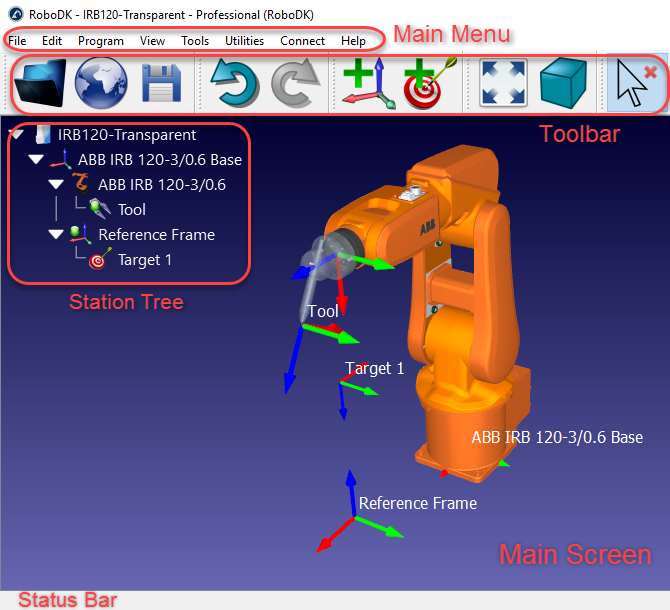
This document provides an overview of the main interface of RoboDK. The main interface is composed of the main menu, the toolbar, the station tree, the status bar and the 3D view.
●The Main Menu is located at the top. All available actions and options are available from this menu.
●The Toolbar contains graphical icons that allow quick access to frequently used actions in the menu. More information available in the Toolbar section.
●The Station Tree lists all the components (items) that are present in the station. These items can be robots, tools, objects, targets or specific settings for manufacturing or calibration purposes. The tree allows understanding and modifying the dependency that exists in the real environment. For example, a target can be attached to a specific reference frame, this reference frame can be attached to the robot base frame, robot tools are usually attached to the robot, etc.
●The Status Bar is located at the bottom and may display useful tips for certain operations.
●The 3D view (Main Screen) displays the view in a 3D virtual environment and reproduces the Station Tree with its hierarchy
Double clicking an item (in the tree or the 3D view) will display a new window with the item’s properties. For example, double clicking a robot will display the Robot Panel. These windows can be closed by selecting the cross at the top right of the sub window.
As an exception, double clicking a target will move the robot to that target. If a target is just selected once (instead of double clicked) the robot will simulate a linear or a joint movement from its current position to that target.
Robot Panel
Double click a robot to open the robot panel (you can double click it in the tree or the 3D view). It is possible to jog the robot axes using the Joint axis jog section and enter specific joint axis values in the text boxes. The joint values and the robot coordinates should match with the values displayed by your robot controller.
You can double click the joint limits to modify the robot axis limits. By default, RoboDK uses the same joint limits used by the robot controller (physical hardware limits). Some applications may require more constrained joint limits (software limits). The joint values can be copied 

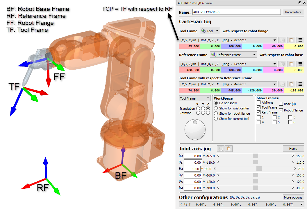
The Cartesian Jog section displays all the information related to the robot kinematics:
●The Tool Frame (TF) with respect to the Robot Flange (FF) defines where the selected Tool Frame is located with respect to the Robot Flange. The Robot Flange is always the same, however, the Tool Frame changes depending on the tool that is mounted on the robot. This relationship is also known as UTOOL, ToolData or just Tool in most robot controllers. The Robot Tool is also known as the TCP (Tool Center Point). The Selected Tool becomes the “Active” tool. The active tool is used when creating new targets and programs. The selected tool displays a green mark in its icon: 
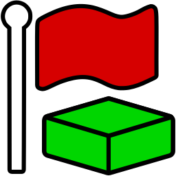
●The Reference Frame (RF) with respect to the Robot Base (BF) defines where the Reference frame is located with respect to Robot Base Frame. The Robot Base Frame never moves, however, different Reference Frames can be used to position any objects with respect to the same Robot Base Frame. This relationship is also known as UFRAME, WorkObject MFRAME or Reference in most robot controllers. The selected reference frame in the robot panel becomes the “Active” reference frame. The active reference frame is used as a reference for new targets and robot programs. The selected reference frame displays a green mark in its icon: 
●The Tool Frame (TF) with respect to the Reference Frame (RF) shows the position of the active TCP with respect to the active reference frame for the current position of the robot. Modify this value to move the robot. The joint axes are recalculated automatically. These Cartesian coordinates are recorded when a new target is created (Program➔Teach Target), together with the robot axes. The target is also attached to the Active reference frame.
A list of possible configurations is available in the Other configurations section. The robot configuration defines a specific state of the robot without crossing any singularities. Changing the configuration requires crossing a singularity. More information available in the Robot Configurations section.
Finally, the Parameters button at the top right allows making some kinematic adjustments, selecting the preferred post processor or extract accurate parameters after a robot calibration project. Modifying these values should only be required in specific circumstances.
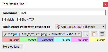
Robot Tool (TCP)
Double click a Robot Tool
Selecting More options… allows applying a scale factor to the geometry of the tool or move the geometry with respect to the robot flange. Altering these values has no impact on robot programs. The geometry is used for display purposes and collision checking. (keeping the TCP intact).
Reference Frame
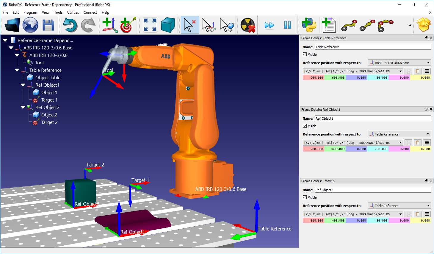
Double click a Reference Frame
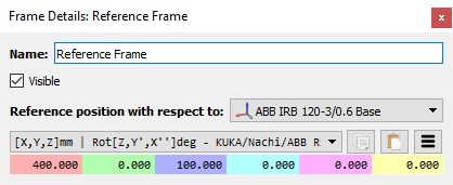
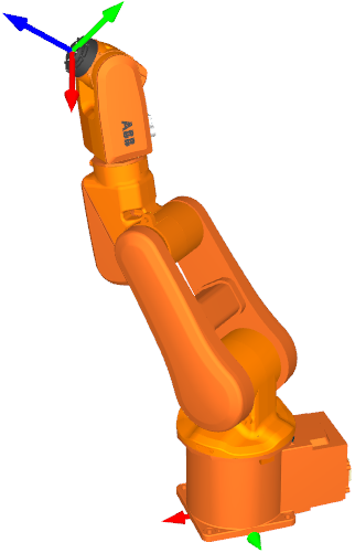
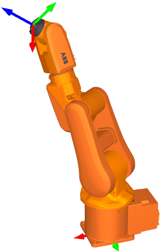
Multiple reference frames can be related to each other to build the dependency that exists in a real application. For example, a table can have a specific position with respect to the robot. Then, two or more objects in the table can have a specific position with respect to the table reference. Moving the table reference will not alter the relationship between the objects and the table but will alter the relationship of all the objects with respect to the robot. The following image shows such an example.
Robot Target
Robot targets allow you to record specific robot positions so that the robot can be moved to that location.
Follow these steps to add a new target and see the information attached to it:
●Select Program➔
This will record the current position of the robot using the active reference frame
●Right click a target, then select More Options… (F3) to see the recorded pose and joint values.
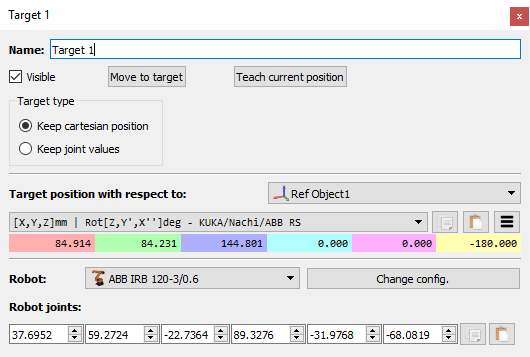
Creating a new target records the TCP with respect to the reference frame in the Cartesian space as well as the current robot axes. By default, RoboDK creates targets as Cartesian targets (Keep cartesian position 
On the other hand, it is possible to specify the target in the joint space (Keep joint values 
It is common practice to use joint targets to reach a first approach position close to the working area, then, Cartesian targets ensure that the toolpath is not altered if the reference frame or the tool frames are modified.
It is possible to see other configurations to reach the same pose with the robot. More information in the next section.
Robot Configurations
One robot configuration defines a specific state of the robot. Changing the configuration requires crossing a singularity. Robot controllers can’t cross a singularity when a linear movement is being made (a joint movement would be required for that).
In other words, to accomplish a linear movement between two targets the robot configuration must be the same for the complete movement, including the first and last points.
Right click a robot and select Change configuration to open the robot configurations window. It is also possible to open this window by selecting More options in the robot panel.
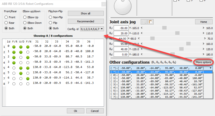
For a standard 6-axis robot there are typically 8 different configurations for any position of the robot if we assume each robot axis can move one full turn. In practice, joint limits can be more or less constrained depending on the robot. Therefore, it may be possible to have from 1 to more than 100 different robot configurations for a specific location depending on the robot.
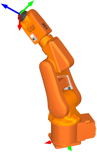
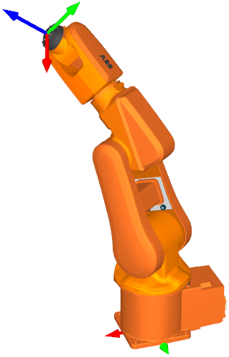
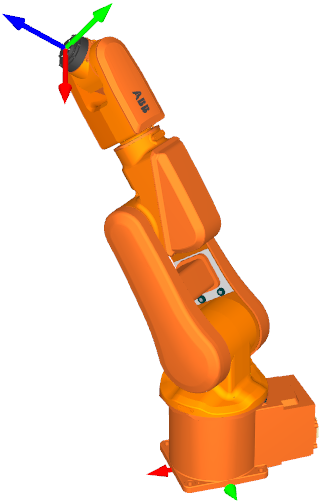
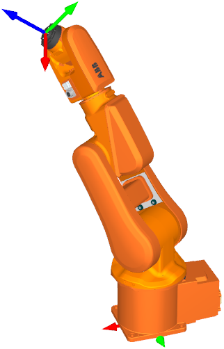


One robot configuration defines a specific way (assembly mode) of reaching a position with the robot. For example, the robot can have the elbow up or the elbow down (Up vs. Down, or U/D), at the same time it can be facing the target or the base can rotate 180 degrees to reach the target backwards (Front vs. Rear, or F/R). Finally, joint 5 can flip by switching the sign at the same time axis 4 and axis 6 compensate for that move (Flip vs. Non-Flip, or F/N). In total, this provides the 2*2*2=8 configurations.
Object Settings
Objects can be loaded in RoboDK using 3D file formats such as STL, STEP or IGES. Double click an object in the tree or the 3D view to open the settings window.
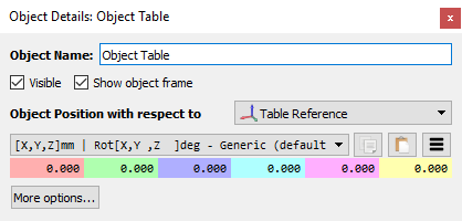
It is possible to set or view the position with respect to any reference frame. However, objects are usually set up on reference frames and it is recommended to move the reference frame if an object needs to be moved. Objects can also be grabbed by robot tools after a certain simulation event occurs.
The More options… menu allows changing the object color, applying a scale factor or moving the geometry with respect to its own reference frame.
Main Menu
The Main menu is divided in the following sections:
1.File menu: Allows importing new files (3D geometry, robots, tools, toolpaths, …) and opening or saving RoboDK projects (RDK file extension).
2.Edit menu: Allows to cut/copy/paste an item or a group of items and do undo/redo actions.
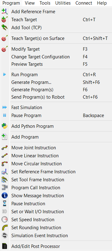
3.Program menu: Allows creating or modifying robot programs and other related options for Offline Programming (OLP).
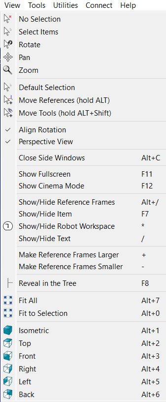
4.View menu: Provides useful actions to navigate in 3D and set up specific views.
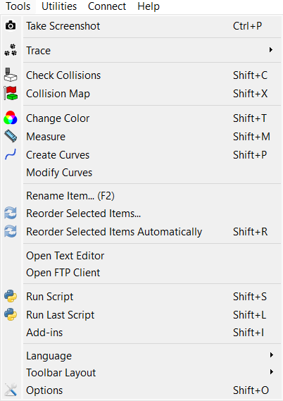
5.Tools menu: Provides general tools such as checking for collisions, measuring points, or opening the main options.
6.Utilities menu: Allows performing specific operations such as using robots for manufacturing operations, calibrating a TCP or a reference frame, using robots as a 3D printer or as a 5-axis CNC, calibrate a robot... These operations might require a specific license option.
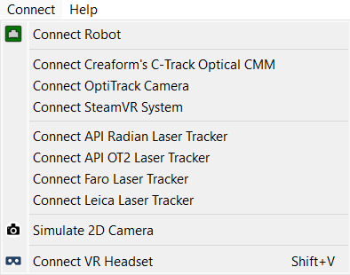
7.Connect menu: Allows connecting to a robot, a measurement system or simulate cameras.
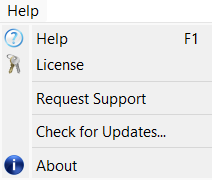
8.Help menu: Allows opening the online documentation (F1), check for updates or set up a license.
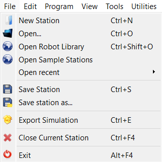
File Menu
The File menu of RoboDK allows you to open and save RoboDK projects. You can also load any type of file supported by RoboDK or export your project using different formats or methods.


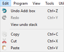
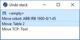
Edit Menu
Undo (Ctrl+Z) and Redo (Ctrl+Y) actions are accessible from the Edit menu. The history of undo actions is also available and allows reverting changes, backwards or forward, to a specific state by selecting the action.
It is also possible to 
Program Menu
The program menu contains all the components related to Offline Programming (OLP) and program generation. It is possible to add new programs, reference frames, targets or tools to robots. These Offline Programming components (reference frames, tools, targets, etc.) appear on all programs generated offline.


The Program Instructions section of the Offline Programming document provides more information about available program instructions through the GUI.
Finally, it is possible to 
View Menu
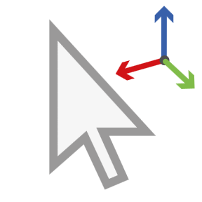
Most options required to navigate in 3D are available from the View menu. It is possible to Rotate, Pan and Zoom from this menu (as well as by right clicking the 3D view). This is useful for navigating in 3D using a laptop touchpad (instead of a mouse).
To allow a free rotation in any direction uncheck the option: View➔Align rotation. Otherwise, RoboDK locks the station reference to keep the XY plane horizontal by default.
It is possible to show or hide the robot workspace by selecting the asterisk key (*). It is also possible to switch between visible and invisible items by selecting the F7 key.
Tools Menu
You can access generic tools in the Tools menu, such as taking 3D measurements, activate collision checking or activating the robot trace.
Activating the 


It is possible to specify the language of the RoboDK application by selecting Tools➔Language and select the preferred language. RoboDK will be displayed in the selected language immediately.
Toolbar Layout allows setting up the default toolbar. Alternatively, it is possible to specify a toolbar for a more basic or more advanced usage.
Select 
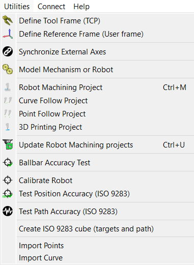
Utilities Menu
The utilities menu allows performing specific tasks to setup your robot and perform specific manufacturing operations such as robot machining, drilling or 3D printing.

The
The
Select 3D print project to generate a robot 3D printing program for a specific object. The object must be available in the RoboDK station. The 3D printing toolpath is converted to G-code behind the scenes using a Slicer and then treated like a 3-axis machining toolpath. More information available in the robot 3D printing section.
The Ballbar Accuracy test allows checking the robot performance using a Telescoping Double Ballbar device. More information about robot ballbar testing available here: https://robodk.com/ballbar-test.

Connect Menu
It is possible to connect to a robot and enter the connections parameters, such as the robot IP, FTP username and FTP password. Setting up a robot connection allows transferring programs through FTP or running programs directly from the PC.
New robot drivers can be developed by end users, more information available in the robot drivers section.
It is also possible to connect to measurement systems such as laser trackers or the Creaform Optical CMM. This allows to fully automate robot calibration and performance testing.
Help Menu
Selecting help in RoboDK opens this documentation online. Also, when you press F1, RoboDK displays the Help topic related to the item currently selected.
Select Check for Updates… to check if an update is available. A message will pop up with a recommended update or just notifying that the current version is already up to date. If no message pops up it means that a firewall is blocking communication between RoboDK and the internet.
Modern Icons
RoboDK 5.7 and newer versions benefit from redesigned icons, which can be activated with Tools➔Option➔General➔Use modern icons. The table below provides an overview of the main icons and their new design.
Legacy | Modern |
|
|
| Open |
|
| Open online library |
|
| Save Station |
|
| Undo |
|
| Redo |
|
| Add a reference frame |
|
| Add a new target |
|
| Fit All |
|
| Isometric View Display the default 3D isometric view |
|
| Move reference Frames |
|
| Move TCP (robot tool) |
|
| Check collisions |
|
| Fast simulation |
|
| Pause simulation |
|
| Add Program |
|
| Add Python Program |
|
| Move Joint Instruction |
|
| Move Linear Instruction |
|
| Export Simulation |